Puncturing device
US20070135828A1
2007-06-14
10/565,395
2003-12-01
✅ Patent granted
US 7,842,059 B2
2010-11-30
WO; PCT/PL03/00132; 20031201
WO; WO2005/009238; 20050203
Anhtuan T Nguyen | Jonathan W Miles
2024-10-16
Abstract:
The device is built of a housing (1), wherein a push button (3) is positioned, and the puncturing needle (5), wherein the push button (3) has arms (7, 8) to guide the push button (3) inside the housing (1), and a driving spring (11), one end of which is linked to the push button (3), and the other end drives the puncturing needle (5), and the puncturing needle (5) has breakable wings (17, 18), which rest against the breaking edge (19) of the housing (1). The device has moreover two return springs (13, 14), each of which is connected to one of the arms (7, 8) of the push button (3), and two side juts (15, 16), each of which is positioned between one of the return springs (13, 14) and the other end of the driving spring (11).
Assignee:
- HTL-STREFA" SPOLKA AKCYJNA 8 🇵🇱 OZORKOW, Poland
Interested in similar patents?
Get notified when new applications in this technology area are published.
Classification:
A61B5/15144 » CPC main
Measuring for diagnostic purposes ; Identification of persons; Devices for taking samples of blood specially adapted for taking samples of capillary blood, e.g. by lancets; Devices intended for single use, i.e. disposable comprising driving means, e.g. a spring, for retracting the piercing unit into the housing
A61B5/150022 » CPC further
Measuring for diagnostic purposes ; Identification of persons; Devices for taking samples of blood; Details; Source of blood for capillary blood or interstitial fluid
A61B5/150435 » CPC further
Measuring for diagnostic purposes ; Identification of persons; Devices for taking samples of blood; Details; Details of piercing elements or protective means for preventing accidental injuries by such piercing elements; Design of piercing elements; Pointed piercing elements, e.g. needles, lancets for piercing the skin Specific design of proximal end
A61B5/150541 » CPC further
Measuring for diagnostic purposes ; Identification of persons; Devices for taking samples of blood; Details; Details of piercing elements or protective means for preventing accidental injuries by such piercing elements; Design of protective means for piercing elements for preventing accidental needle sticks, e.g. shields, caps, protectors, axially extensible sleeves, pivotable protective sleeves Breakable protectors, e.g. caps, shields or sleeves, i.e. protectors separated destructively, e.g. by breaking a connecting area
A61B5/150618 » CPC further
Measuring for diagnostic purposes ; Identification of persons; Devices for taking samples of blood; Details; Details of piercing elements or protective means for preventing accidental injuries by such piercing elements; Design of protective means for piercing elements for preventing accidental needle sticks, e.g. shields, caps, protectors, axially extensible sleeves, pivotable protective sleeves; Joining techniques used for protective means Integrally moulded protectors, e.g. protectors simultaneously moulded together with a further component, e.g. a hub, of the piercing element
A61B5/150923 » CPC further
Measuring for diagnostic purposes ; Identification of persons; Devices for taking samples of blood; Details; Preventing re-use by means for destroying components or parts, e.g. by cutting or piercing
A61B5/15111 » CPC further
Measuring for diagnostic purposes ; Identification of persons; Devices for taking samples of blood specially adapted for taking samples of capillary blood, e.g. by lancets; Details; Piercing procedure; Piercing being assisted by a triggering mechanism Semi-automatically triggered, e.g. at the end of the cocking procedure, for instance by biasing the main drive spring or when reaching sufficient contact pressure, the piercing device is automatically triggered without any deliberate action by the user
A61B5/15117 » CPC further
Measuring for diagnostic purposes ; Identification of persons; Devices for taking samples of blood specially adapted for taking samples of capillary blood, e.g. by lancets; Details; Driving means for propelling the piercing element to pierce the skin, e.g. comprising mechanisms based on shape memory alloys, magnetism, solenoids, piezoelectric effect, biased elements, resilient elements, vacuum or compressed fluids comprising biased elements, resilient elements or a spring, e.g. a helical spring, leaf spring, or elastic strap
A61B5/15142 » CPC further
Measuring for diagnostic purposes ; Identification of persons; Devices for taking samples of blood specially adapted for taking samples of capillary blood, e.g. by lancets Devices intended for single use, i.e. disposable
A61B17/32 IPC
Surgical instruments, devices or methods, e.g. tourniquets Surgical cutting instruments
Description
BACKGROUND OF THE INVENTION1. Field of the Invention
This invention relates to the puncturing device designed particularly for puncturing patient's skin in order to collect a blood sample for diagnostic purposes.
2. Description of the Related Art
The U.S. Pat. No. 5,356,420 discloses a puncturing device comprising a sleeve and a push element positioned at the first end of the sleeve. The other end of the sleeve ends with a bottom with an opening therein. Inside the sleeve a piston is slidably mounted, terminating with a push rod at the end closer to the push button, and with a puncturing tip at the end closer to the bottom opening. Inside the sleeve between the push element face and the piston, a drive spring is located, and between the piston and the sleeve bottom a return spring is placed. The piston comprises wings located on its outer perimeter which rest on an internal projection of the sleeve.
Further, the U.S. Pat. No. 5,439,473 discloses a lancet designed for puncturing patient's skin for the sake of collecting small blood samples. The lancet has elongated housing, wherein a movable member is disposed sliding along the housing axis, while the housing has a top opening for the lancet push button, and a bottom opening for the piercing blade. The movable member consists of a flat spring, one end of which is linked to the push button. The push button has two upper arms perpendicular to its surface, and those arms have hooked ends disposed in oblong openings of the housing side walls. The other end of the movable member flat spring is joined with a holder wherein the piercing blade is fixed. The holder lower portion has two lower arms parallel to the upper arms. The lower arms have moreover upwardly directed, triangle shaped tips, which rest upon the lower edges of the oblong openings of the housing walls. All parts of the movable member are made of plastics.
When the patient's skin is being punctured, the lancet press button is pressed, by what the flat spring of the movable member is tensed, and hooked ends of the upper arms press against the tips of the lower arms of the movable member. Next the release of the lower arms occurs, the flat spring rebounds, and the patient's skin is punctured by the piercing blade which passes through the housing bottom opening. After puncturing the flat spring assumes free position, and the piercing blade retracts inside the lancet housing.
Further, the U.S. Pat. No. 5,755,733 discloses a lancet device consisting of a lancet assembly and a holder linked to the lancet assembly, wherein the lancet assembly has a lancet with piercing portion, and an ejector which pushes the lancet out. In the known lancet device the lancet piercing portion is covered with plastic material.
SUMMARY OF THE INVENTIONAccording to the present invention, the puncturing device comprises a housing wherein the push button and the puncturing needle is disposed, wherein the push button has arms to guide the push button inside the housing, and a driving spring, one end of which is linked to the push button, and the other end drives the puncturing needle, and the puncturing needle has breakable wings which rest against the breaking edge of the housing, and it comprises at least one return spring connected to the push button arms, while the puncturing needle has at least one side jut disposed inside the device between the return spring and the other end of the driving spring.
Preferably it has two return springs, each of which is connected to one arm of the push button, and two side juts, each of which is disposed inside the device between one of the return springs and the other end of the driving spring.
Preferably the return springs are connected approximately perpendicularly to the lower portions of the push button arms.
Preferably the first end of the driving spring is connected to the push button face.
Preferably the other end of the driving spring ends with a pusher for the puncturing needle.
Preferably the driving spring is S-letter shaped.
Preferably the return springs are flat springs.
An advantage of the solution according to the present invention is a fact that it facilitates puncturing the patient's skin in a safe and cost-efficient manner.
BRIEF DESCRIPTION OF THE DRAWINGSThe accompanying drawings, which are incorporated in, and form a part of the specification, illustrate the embodiment of the present invention and, together with the description, serve to explain the principles of the invention. In the drawings:
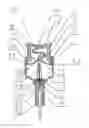
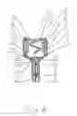
FIG. 1 shows the longitudinal section of the puncturing device according to the invention before use;
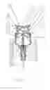
FIG. 2 shows the device from the FIG. 1 before breaking the wings;
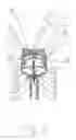
FIG. 3 shows the device from the FIG. 1 after breaking the wings; and
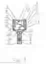
FIG. 4 shows the device from the FIG. 1 during puncturing the patient's skin, whereas the same elements of the puncturing devices depicted on the drawing have the same designations.
DETAILED DESCRIPTION OF THE INVENTIONReference will now be made in detail to the preferred embodiment of the invention, the example of which is illustrated in the accompanying drawings.
The puncturing device depicted in the FIG. 1 is built of a housing (1), where in the top opening (2) of the housing a push button (3) is positioned, while in the lower, elongated opening (4) of the housing (1) is in turn disposed the puncturing needle (5). The push button (3) is made of plastic, and consists of the push button face (6) and parallel to the housing (1) axis and expanding from the opposite ends of the push button face (6) arms (7, 8) to guide the push button (3) in the housing (1). Each of the arms (7, 8) has also a detent (9, 10) to fix the push button (3) in the housing (1). Moreover the push button (3) has a driving spring (11) shaped like the letter “S”, which is linked on one side to the push button face (6), and on the other end tipped with the pusher (12) for the puncturing needle (5), and has two flat return springs (13, 14), each of which is mounted approximately parallel to lower portions of the arms (7, 8) of the push button (3). The puncturing needle (5), which is disposed in the lower, oblong opening (4) of the housing (1), has in its upper portion two side juts (15, 16), which are disposed in the device according to the invention between the pusher (12) of the driving spring (11) of the push button (3), and the return springs (13, 14), and in its lower portion breakable wings (17, 18), which rest against the upper edge of the lower, elongated opening (4), which is the breaking edge (19) for the wings (17, 18). Inside the puncturing needle (5) a lancet (20) is disposed, while the puncturing portion (21) of the lancet (20) has a shield (22) of plastic.
The operation of the device according to the invention is as follows:
The position of the device elements before use is shown in the FIG. 1, where the push button (3) is in the upper position, and the breakable wings (17, 18) rest against the breaking edge (19). After detachment of the shield (22) of the piercing portion (21) of the lancet (20), the push button face (6) is pressed, causing compressing the driving spring (11), as it is depicted in the FIG. 2, to the moment when the driving spring (11) is maximally compressed, and breaking off the wings (17, 18) occurs. Then the driving spring (11) expands, in result of which the puncturing needle (5) with the lancet (20) displaces in the lower opening (4) of the housing (1), while the side juts (15, 16) of the puncturing needle (5) press the return springs (13, 14), as it is shown in the FIG. 3. Next the puncturing portion (21) of the lancet (20), protruding outside the lower opening (4) of the housing (1) punctures the patient's skin, while the side juts (15, 16) of the puncturing needle (5) cause maximum deflection of the return springs (13, 14), as it is shown in the FIG. 4. After puncturing the skin, the return springs (13, 14) pull, with the help of the side juts (15, 16), the puncturing needle (5) inside the lower opening (4) of the housing (1), while the driving spring (11) and the return springs (13, 14) are then in free state, as it is shown in the FIG. 3.
Subsequent re-use of the device is not possible because the wings (17, 18) of the puncturing needle (5) are already broken off.
Claims
We claim:1. Puncturing device built of a housing, wherein a push button and a puncturing needle is disposed, wherein the push button has arms to guide the push button inside the housing, and a driving spring, one end of which is linked to the push button, and the other end drives the puncturing needle, and the puncturing needle has breakable wings, which rest against the breaking edge of the housing, characterised by that it comprises at least one return spring connected to the arms (7, 8) of the push button (3), while the puncturing needle (5) has at least one side jut, which is positioned inside the device between the return spring and the other end of the driving spring (11).
2. A device according to the claim 1 characterised by that it has two return springs (13, 14), each of which is connected to one arm (7, 8) of the push button (3), and has two side juts (15, 16), each of which is positioned inside the device between one of the return springs (13, 14) and the other end of the driving spring (11).
3. A device according to the claim 2, wherein the return springs (13, 14) are connected approximately perpendicularly to the lower portions of the arms (7, 8) of the push button (3).
4. A device according to the claim 1, wherein the first end of the driving spring (11) is connected with the push button face (6).
5. A device according to the claim 1, wherein the other end of the driving spring (11) ends with a pusher (12) for the puncturing needle (5).
6. A device according to the claim 1, wherein the driving spring (11) is shaped like the letter “S”.
7. A device according to the claim 1, wherein the return springs (13, 14) are flat springs.
Images & Drawings included:
Sources:
- United States Patent and Trademark Office - verify current appl. status at the USPTO↗
Similar patent applications:
- » 20240148985
Puncturing Devices, Puncturing Systems Including the Puncturing Devices, and Methods Thereof - » 20230310030
PUNCTURE DEVICE, PUNCTURE SYSTEM, OPERATION METHOD OF PUNCTURE DEVICE, AND USAGE METHOD OF GUIDEWIRE - » 20200345950
Puncturing devices, puncturing systems including the puncturing devices, and methods thereof - » 20250090768
PUNCTURE DEVICE AND MEDICINAL SOLUTION ADMINISTERING DEVICE EQUIPPED WITH PUNCTURE DEVICE - » 20100160941
Disposable puncturing device and reusable handling device for a puncturing device - » 20250177646
PUNCTURE DEVICE AND DRUG SOLUTION ADMINISTRATING DEVICE PROVIDED WITH PUNCTURE DEVICE - » 20140121085
RECEIVER-PUNCTURING DEVICE WITH TRANSLATING PUNCTURING DEVICES - » 20190365461
PUNCTURE DEVICE AND CARTRIDGE FOR PUNCTURE DEVICE - » 20130289404
Cover unit for use when inserting a puncture device in an anatomical structure such as a vein or an artery and for maintaining said puncture device in the anatomical structure - » 20160331910
Puncture assisting device and puncture device set
Recent applications in this class:
- » 20250090061 2025-03-20
Single Use Lancing Device - » 20170347934 2017-12-07
Skin pricking device - » 20150297127 2015-10-22
Method and system for providing a single-use safety lancet - » 20150112375 2015-04-23
Lancet pricking device - » 20150105813 2015-04-16
BLOOD COLLECTING APPARATUS, LANCET AND LANCING DEVICE - » 20150073463 2015-03-12
Cam-actuated medical puncturing device and method - » 20150039006 2015-02-05
SINGLE USE LANCET ASSEMBLY - » 20140121693 2014-05-01
Lancing devices - » 20140100481 2014-04-10
Lancing device for taking blood samples - » 20140052023 2014-02-20
Single Use Lancet Assembly
Recent applications for this Assignee:
- » 20160331292 2016-11-17
Blocking mechanism for a patient's skin incision device and a method of controlling of a skin incision device by a blocking mechanism - » 20160228654 2016-08-11
Safety needle device - » 20100318111 2010-12-16
Patient's skin puncturing device - » 20100168775 2010-07-01
Patient's skin puncturing device - » 20090281562 2009-11-12
LANCET - » 20090118754 2009-05-07
Patient's skin puncturing device - » 20080195134 2008-08-14
Patient's skin puncturing device