PACKAGING WITH SUBSEQUENTLY MOLDED FORM-FIT CONNECTION
US20070138192A1
2007-06-21
11/609,637
2006-12-12
Abstract:
The present invention relates to a packaging with a packaging trough, into which a packaging material can be filled and which is closed with a lid, whereby at least one form-fit connection connects the packaging trough with the lid and the connection comprises a first and a second connection means. Furthermore, the present invention relates to a method for the production of a packaging as well as a packaging machine.
Inventors:
- Dietmar Send 5 🇩🇪 Durach, Germany
- Peter Riegger 2 🇩🇪 Wilpoldsried, Germany
- Joachim Dr. Wokurka 1 🇩🇪 Landsberg, Germany
Interested in similar patents?
Get notified when new applications in this technology area are published.
Classification:
B29C65/56 » CPC main
Joining of preformed parts ; Apparatus therefor using mechanical means or mechanical connections, e.g. form-fits
B29C65/58 » CPC further
Joining of preformed parts ; Apparatus therefor using mechanical means or mechanical connections, e.g. form-fits Snap connection
B29C66/542 » CPC further
General aspects of processes or apparatus for joining preformed parts; General aspects of joining tubular articles; General aspects of joining long products, i.e. bars or profiled elements; General aspects of joining single elements to tubular articles, hollow articles or bars; General aspects of joining several hollow-preforms to form hollow or tubular articles; Joining tubular articles, profiled elements or bars; Joining single elements to tubular articles, hollow articles or bars; Joining several hollow-preforms to form hollow or tubular articles; Joining several hollow-preforms, e.g. half-shells, to form hollow articles, e.g. for making balls, containers; Joining several hollow-preforms, e.g. half-cylinders, to form tubular articles joining hollow covers or hollow bottoms to open ends of container bodies
B29C66/545 » CPC further
General aspects of processes or apparatus for joining preformed parts; General aspects of joining tubular articles; General aspects of joining long products, i.e. bars or profiled elements; General aspects of joining single elements to tubular articles, hollow articles or bars; General aspects of joining several hollow-preforms to form hollow or tubular articles; Joining tubular articles, profiled elements or bars; Joining single elements to tubular articles, hollow articles or bars; Joining several hollow-preforms to form hollow or tubular articles; Joining several hollow-preforms, e.g. half-shells, to form hollow articles, e.g. for making balls, containers; Joining several hollow-preforms, e.g. half-cylinders, to form tubular articles one hollow-preform being placed inside the other
B29C66/8322 » CPC further
General aspects of processes or apparatus for joining preformed parts; General aspects of machine operations or constructions and parts thereof characterised by the movement of the joining or pressing tools; Reciprocating joining or pressing tools Joining or pressing tools reciprocating along one axis
B29C66/8432 » CPC further
General aspects of processes or apparatus for joining preformed parts; General aspects of machine operations or constructions and parts thereof; Specific machine types or machines suitable for specific applications; Machines for making separate joints at the same time in different planes; Machines for making separate joints at the same time mounted in parallel or in series Machines for making separate joints at the same time mounted in parallel or in series
B65B7/2857 » CPC further
Closing containers or receptacles after filling; Closing semi-rigid or rigid containers or receptacles not deformed by, or not taking-up shape of, contents, e.g. boxes or cartons by applying separate preformed closures, e.g. lids, covers; Securing closures on containers by deformation of the closure and the container rim
B65D43/0212 » CPC further
Lids or covers for rigid or semi-rigid containers; Removable lids or covers without integral tamper element secured by snapping over beads or projections only on the outside, or a part turned to the outside, of the mouth
B29C51/00 » CPC further
Shaping by thermoforming, i.e. shaping sheets or sheet like preforms after heating , e.g. shaping sheets in matched moulds or by deep-drawing; Apparatus therefor
B29C66/83221 » CPC further
General aspects of processes or apparatus for joining preformed parts; General aspects of machine operations or constructions and parts thereof characterised by the movement of the joining or pressing tools; Reciprocating joining or pressing tools; Joining or pressing tools reciprocating along one axis cooperating reciprocating tools, each tool reciprocating along one axis
B29C2791/001 » CPC further
Shaping characteristics in general Shaping in several steps
B65D2543/00194 » CPC further
Lids or covers essentially for box-like containers; Details of lids or covers for rigid or semi-rigid containers; Overall construction of the lid; Shape of the outer periphery having straight sides, e.g. with curved corners four straight sides, e.g. trapezium or diamond square or rectangular
B65D2543/00296 » CPC further
Lids or covers essentially for box-like containers; Details of lids or covers for rigid or semi-rigid containers; Overall construction of the lid; Materials used Plastic
B65D2543/00527 » CPC further
Lids or covers essentially for box-like containers; Details of lids or covers for rigid or semi-rigid containers; Contact between the container and the lid on the inside or the outside of the container on the inside, or a part turned to the inside of the mouth of the container NO contact
B65D2543/00537 » CPC further
Lids or covers essentially for box-like containers; Details of lids or covers for rigid or semi-rigid containers; Contact between the container and the lid on the inside or the outside of the container on the outside, or a part turned to the outside of the mouth of the container
B65D2543/0062 » CPC further
Lids or covers essentially for box-like containers; Details of lids or covers for rigid or semi-rigid containers; Contact between the container and the lid; Snapping means on the container; Profiles Groove or hollow bead
B65D2543/00694 » CPC further
Lids or covers essentially for box-like containers; Details of lids or covers for rigid or semi-rigid containers; Contact between the container and the lid; Snapping means on the container; Periphery concerned Segments
B65D2543/00731 » CPC further
Lids or covers essentially for box-like containers; Details of lids or covers for rigid or semi-rigid containers; Contact between the container and the lid; Snapping means on the lid; Profiles Groove or hollow bead
B65D41/18 IPC
Caps, e.g. crown caps or crown seals, i.e. members having parts arranged for engagement with the external periphery of a neck or wall defining a pouring opening or discharge aperture; Protective cap-like covers for closure members, e.g. decorative covers of metal foil or paper; Caps or cap-like covers without lines of weakness, tearing strips, tags, or like opening or removal devices; Snap-on caps or cap-like covers non-metallic, e.g. made of paper or plastics
Description
CROSS-REFERENCE TO RELATED APPLICATIONSThis application is a Continuation-in-part and claims benefit from U.S. patent application Ser. No. 11/181,037 filed on Jul. 13, 2005.
The present invention relates to a packaging with a packaging trough, into which a packaging material can be filled and which is closed with a lid, whereby at least one form-fit connection connects the packaging trough with the lid and the connection comprises a first and a second connection means. Furthermore, the present invention relates to a method for the production of a packaging as well as a packaging machine.
Items of packaging as a rule comprise a packaging trough, into which the packaging material, for example foodstuff, can be filled. This packaging trough is then closed with an, as a rule, preformed lid. In order to increase the pull-off force of the lid from the packaging trough after the initial opening, it is advantageous for the re-closure capability if at least one form-fit connection is present between the lid and the packaging trough. This form-fit connection comprises two connection elements, for example a groove and a tongue, whereby the tongue is introduced into the groove.
At present, the connection elements are molded into the lid and into the packaging trough during deep-drawing. Since the lid and the packaging trough must, however, be able to be removed again from the respective deep-drawing die after deep-drawing and one connection element must be able to be introduced into the other, the shape of the connection elements is very greatly restricted with this method.
The problem of the present invention, therefore, was to make available a packaging that does not display the drawbacks of the prior art.
This problem is solved with a packaging with a packaging trough, into which a packaging material can be filled and which is closed with a lid, whereby at least one form-fit connection connects the packaging trough with the lid and the connection comprises a first and a second connection element, wherein at least one connection element has been molded at least partially into the packaging after the packaging trough has been closed with the lid.
It was extremely surprising for the expert and not to be expected that the packaging according to the invention can have an arbitrarily shaped form-fit connection between the lid and the packaging trough. Very great design possibilities of the form-fit connection between the packaging trough and the lid thus arise, so that the force that is required to remove the lid from the packaging trough can for example be adjusted very exactly. The packaging according to the invention can be produced in a straightforward manner and cost effectively.
According to the invention, the packaging comprises a packaging trough, into which the packaging material can be filled, and a lid. Both the packaging trough and the lid are preferably manufactured from a plastics material and are deep-drawn in each case. The plastic material may be comparatively stiff and/or foamed. At least one, but preferably several, form-fit connections are arranged between the lid and the packaging trough, whereby the form-fit connection is brought about in such a way that the force that is required to detach the lid from the packaging trough is increased. The form-fit connections can be distributed arbitrarily over the circumference of the packaging. Furthermore, the form-fit connections can be combined with a joint, whereby at least one form-fit connection is then arranged opposite the hinge (joint). Furthermore, the form-fit connections can also be used as snap connections for the re-closure of the items of packaging. According to the invention, the form-fit connection comprises a first and a second connection means, which engage into one another and thus bring about the form-fit connection. All connection elements familiar to the expert can be considered as connection elements, with which it is possible to achieve a form closure between the packaging trough and the lid. Preferably, however, the connection element is a groove and tongue connection or two spherical part-shells which engage into one another. The connection preferably extends parallel to the transport direction of the film web from which the packaging is produced. This embodiment of the present invention simplifies the dies and their arrangement in a packaging machine which are required to mould the connection elements of the form-fit connection into the packaging trough and the lid.
According to the invention, the packaging has at least one, but preferably two or more, form-fit connections.
The lid and the packaging trough are preferably sealed to one another in the region of a sealing plane. This sealing is preferably peelable, so that the packaging can be closed again by means of the form-fit connection.
The connections are preferably inserted by thermal molds into the packaging trough. The connection should preferably be inserted from the inside to the outside, i.e. the circumference of the packaging increases in the region of the connection. The advantage of this design of the present invention is that the surface by which the goods can be removed from the packaging is not reduced by the inner moldings, or that no additional outward bulges have to made into which the connections are then shaped, as disclosed in EP 0 367 603 A2.
The inner molding is preferably located in the lateral walls of the packaging trough.
The lid is preferably sealed to the packaging trough. This sealing is preferably peelable so that the connection serves as a resealing device after the packaging is opened for the first time. The lid is preferably sealed to the packaging trough along an essentially horizontal sealing plane
The items of packaging may be arbitrarily shaped, but the items of packaging preferably have an essentially square or round base surface.
A further subject-matter of the present invention is a method for the production of a packaging having a packaging trough and a lid, whereby the packaging trough is closed with the lid, wherein a form-fit connection, which connects the lid with the packaging trough, is subsequently molded into the packaging.
With the method according to the invention, it is possible to produce items of packaging which have arbitrarily shaped form-fit connections between the packaging and the lid. The method according to the invention can be carried out in a straightforward manner and cost effectively.
In a preferred embodiment of the method according to the invention, the lid is sealed to the packaging trough before the form-fit connection has been produced. The sealing is preferably peelable.
The packaging is preferably manufactured in cycles, i.e. one format at a time, consisting of several items of packaging, is always conveyed in cycles along a packaging machine. The connections are then molded in whilst the items of packaging to be produced are stationary. For this purpose a die is displaced preferably vertically, which die has at least one, preferably several embossing means. The connections are made with these embossing means.
For the actual manufacture of the connections the embossing means are preferably displaced for this purpose transversely to the direction of conveying of the items of packaging along the packaging machine, thereby molding the connection into the packaging trough or the lid. After manufacture, the embossing means are retracted and moved vertically upwards so that the items of packaging can continue to be conveyed by one cycle.
The embossing means preferably interact with a counter-bearing, in order for example to prevent the packaging from becoming misshaped when the connection is molded in. It is preferable, particularly in the case of round items of packaging, for the counter-bearings to be arranged so that they are vertically displaceable. As soon as the items of packaging are located underneath the embossing means, the counter-bearings are raised so that they rest on the packaging troughs. Before the items of packaging are conveyed further, the counter-bearings are lowered again.
Counter-bearings are preferably adjusted before lowering.
A further subject-matter of the present invention is a packaging machine, which has an embossing means with which a connection element can be molded into the packaging.
This embossing means is preferably mounted so as to be displaceable crosswise to the direction of transport of the film web, so that it can be brought reversibly into engagement with the packaging trough and the lid. Furthermore, it is preferably arranged so that it is vertically displaceable so that it can be removed from the area of the packaging after the connection has been molded in.
The packaging machine according to the invention preferably works cyclically. The items of packaging of one size are in this case always conveyed further cyclically by a certain distance. The packaging is processed and the connection molded in whilst the items of packaging are stationary.
The packaging machine according to the invention also preferably has counter-bearings, with which the embossing means cooperate. By means of this preferred embodiment of the present invention, the connection means of the form-fit connection can be molded more rapidly and more exactly into the packaging trough and into the lid. Furthermore, adjustment of the packaging during manufacture of the connection is avoided.
These counter-bearings may be arranged so that they are vertically displaceable. This is particularly preferred in the case of round items of packaging. The counter-bearings are preferably rotated about a vertical axis before lowering until a recess provided in the counter-bearing overlaps the molded in connection. It is then possible to lower the packaging trough without problem.
The packaging machine according to the invention preferably has a sealing station, in which the lid is sealed to the packaging trough. The embossing means are preferably downstream of the sealing station, in relation to the running direction of the film from which the packaging trough and the lid is produced.
The invention will be explained below with the aid of FIGS. 1 to 4. These explanations are merely by way of example and do not restrict the general ideas of the invention. The explanations apply equally to all the subject-matters of the present invention.
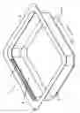
FIG. 1 shows the packaging according to the invention,
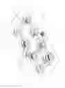
FIG. 2 shows two possible embodiments of the form-fit connection,
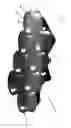
FIG. 3 shows the packaging machine according to the invention with the embossing means and
FIG. 4 shows further details of the embossing means according to FIG. 3,
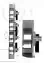
FIG. 5 shows a format on round counter-bearings for manufacturing a packaging according to the invention,
FIG. 6 shows a section and detail of the counter-bearings according to FIG. 5,
FIG. 7 shows the drive of the counter-bearings.
FIG. 1 shows the packaging according to the invention, which comprises a packaging trough 2 and a lid 3. A packaging material, for example foodstuff, can be placed into packaging trough 2. Packaging trough 2 is then closed with lid 3. After the packaging trough has been closed with the lid, form-fit connection 4 is molded into the lid and/or the packaging trough. In the present case, the form-fit connection is molded both into lid 3 and into packaging trough 2. The packaging according to the invention is produced on a packaging machine, whereby the packaging trough and the lid are either placed as ready molded parts into the packaging machine or are molded into a plane film web, for example by deep-drawing. In each case, the items of packaging are transported, preferably cyclically, along the running direction represented by the arrow inside the packaging machine. The expert will recognize that, in the present case, form-fit connection 4 is arranged parallel to the running direction of the packaging machine, which considerably simplifies the design of the packaging machine, this being explained in greater detail with the aid of FIGS. 3 and 4. The lid and the packaging trough are sealed to one another in a peelable manner in the region of the sealing plane before the form-fit connection has been molded into the packaging.
FIG. 2 shows two possible design shapes of the form-fit connection. The left-hand representation shows a groove tapering to a point, which extends into and out of the plane of the paper. Due to the fact that the form-fit connection is molded into the lid and the packaging trough only after the lid has been placed onto the packaging trough, it is possible to produce shapes of the form-fit connection which were not possible according to the prior art. For example, it was not possible to produce a groove and tongue in such a pointed fashion depicted in the left-hand representation, without the latter either no longer being able to be removed from the mould or becoming damaged during the fitting together of the lid and the packaging trough.
The right-hand part of FIG. 2 represents a hemispherical design of the form-fit connection. The expert will understand that it is advantageous for several such spherical form-fit connections to be arranged over the circumference of the packaging trough. Reference is further made to the comments concerning the left-hand embodiment according to FIG. 2.
FIG. 3 represents the embossing means of the packaging machine according to the invention. The packaging trough (not shown) closed with a lid is transported into the plane of the paper and stopped for a short time in recesses 12 of die 8. As soon as the packaging is located inside recess 12 in a stationary position, embossing means 5, 6, which are located on displacement means 9, 10, are lowered and displaced to the right or to the left, so that they engage with the packaging and mould the respective connection elements essentially simultaneously into the lid and into the packaging trough. During the molding, embossing means 5, 6 cooperate with counter-bearings 7, which are arranged on die 8. As soon as the connection elements of the form-fit connection have been produced, the dies are again moved back and the packages thus completed are transported one cycle onwards. The movement of adjustment elements 9, 10 is represented by the two double arrows. Due to the fact that the form-fit connections are parallel to the direction transport of the packaging, die 8 does not have to be designed lowerable, and this represents a considerable design advantage. Embossing means 5, 6 can be designed heatable.
FIG. 4 essentially corresponds to FIG. 3, whereby in the present case tubes 11 are also represented, with which the displacement of adjustment means 9, 10 crosswise to the direction transport of the film web is brought about.
FIG. 5 shows a two-row format, each with four counter-bearings 7 for manufacturing the connecting elements according to the invention on items of packaging which are arranged in a suitable format. These counter-bearings 7 each have a groove 13, which interacts with the embossing means (not shown) in order to emboss the connecting element according to the invention into the lateral wall of the packaging trough and into the lid. Furthermore, the counter-bearing according to the invention has four recesses 14 on which the groove is interrupted and which extend as far as the upper edge of the counter-bearing 7. Two heated embossing means (not shown) are pressed outwards transversely to the direction of conveying represented by the arrow, thereby embossing the form-fit connection in the lid and the lateral wall of the packaging trough. The embossing means are then retracted and at the same time or shortly thereafter the counter-means are rotated 45° clockwise or anticlockwise by means of a drive until recesses 14 overlap the form-fit connections in the items of packaging. Counter-bearings 7 can then be lowered without damaging the form-fit connection and the packaging troughs provided with the form-fit connection can be conveyed further one cycle. Between two cycles the counter-bearings can be rotated 45° back into their original position, and as soon as the further conveyance of the packaging troughs is completed, they can then be brought into engagement with a further format of items of packaging in order to insert the form-fit connections into the packaging.
FIG. 6 shows a section through a row of counter-bearings 7 and an enlargement B. It can clearly be seen that the counter-bearings 7 are rotatable about a vertical axis 15. The adjustment is in this case made 450 clockwise and anticlockwise by means of a toothed belt 17, which engages with a toothed wheel 16. The expert understands that any drive may also be considered here. The expert understands that the connections need not be molded in transversely to the direction of conveying but may also be arranged at any other point.
The drive for toothed belt 17 is shown in FIG. 7. In this case the drive is provided by a pneumatic cylinder 16, which drives a lever 19 alternately clockwise and anticlockwise. This drive is transmitted by toothed belt 17 to all ten toothed wheels 16 and drives them synchronously. The expert understands that any other drive may be considered here.
Claims
1. A packaging (1) with a packaging trough (2), into which a packaging material can be filled and which is closed with a lid (3), whereby at least one form-fit connection (4) connects the packaging trough (2) with the lid (3) and the connection (4) comprises a first and a second connection element (4′, 4″), characterized in that at least one connection element (4′, 4″) has been molded at least partially into the packaging (1) after the packaging trough (2) has been closed with the lid (3).
2. The packaging according to claim 1, characterized in that both connection elements (4′, 4″) are molded into the packaging after the packaging trough (2) has been closed with the lid (3).
3. The packaging according to claim 1, characterized in that the connection elements are groove (4′) and tongue (4″).
4. The packaging according to claim 1, characterized in that the form closure increases the pull-off force of the lid (3) from the packaging trough (2).
5. The packaging according to claim 1, characterized in that the connection (4) is arranged parallel to the direction of transport of the items of packaging in a packaging machine.
6. The packaging according to claim 1, characterized in that it has at least two form-fit connections (4).
7. The packaging according to claim 1, characterized in that the lid (3) and the packaging trough (2) are sealed to one another, preferably in a peelable manner.
8. A method for producing a packaging (1) having a packaging trough (2) and a lid (3), whereby the packaging trough (2) is closed with the lid (3), characterized in that a form-fit connection (4), which connects the lid with the packaging trough, is then molded into the packaging.
9. The method according to claim 8, characterized in that the connection (4) is molded into the packaging after the lid has been sealed to the packaging trough.
10. The method according to claim 1, characterized in that the connections are preferably molded in transversely to the direction of conveying.
11. The method according to claim 1, characterized in that the connections are molded in with an embossing means which interacts with a counter-bearing (7), and in that the counter-bearing is rotated and lowered after molding in.
12. A packaging machine having embossing means (5, 6) with which at least one connection element (4′, 4″) can be molded into a packaging.
13. The packaging machine according to claim 10, characterized in that the embossing means (5, 6) are mounted so as to be displaceable crosswise to the direction of transport of the film web.
14. The packaging machine according to claim 1, characterized in that the embossing means (5, 6) cooperate with counter-bearings (7).
15. The packaging machine according to claim 1, characterized in that it has a sealing station and that the embossing means (5, 6) are downstream of the sealing station.
16. The packaging machine according to claim 13, characterized in that the counter-bearings (7) are arranged so that they are vertically displaceable.
17. The packaging machine according to claim 13, characterized in that the counter-bearings (7) are rotatably mounted.
18. The packaging machine according to claim 1, characterized in that it has a sealing station and in that the embossing means (5, 6) are arranged after the sealing station.
Images & Drawings included:


Sources:
- United States Patent and Trademark Office - verify current appl. status at the USPTO↗
Similar patent applications:
Recent applications in this class:
- » 20220063208 2022-03-03
System for joining ends of rubber strips to supply an extruder - » 20170210062 2017-07-27
Substrate-bonding device and method of the same - » 20160176105 2016-06-23
System for mounting objects to polymeric membranes - » 20160016357 2016-01-21
Method for producing a decorated, surface-structured laminate - » 20150135499 2015-05-21
Method of manufacturing custom sized plastic tote having intermediate sleeve - » 20150013903 2015-01-15
COUPLING DEVICE FOR TUBE WITH ANNULAR CORRUGATIONS - » 20140239541 2014-08-28
Electrochemical fabrication method including elastic joining of structures - » 20140096891 2014-04-10
Electrified bird repellent track - » 20130153289 2013-06-20
Crystal used for closing the top of the case of a portable object and method of welding a crystal of this type - » 20120137497 2012-06-07
Electrochemical fabrication method including elastic joining of structures