Tension positioning apparatus and method of use for manufacturing poles and columns
US20070151089A1
2007-07-05
11/441,486
2006-05-26
Abstract:
The present invention provides for an apparatus and method that allows manufacturing of steel poles and steel honey comb columns. It consists of vertically placing previously cut strips of a desired substance, generally anticipated to be metallic in nature, in a tension positioning apparatus that applies vertical, or longitudinally along the length of the strips, tension to the strips. When each of the strips are in tension, they are positioned into a desired polygonal, generally cylindrical, shape. The adjoining sides of the strips can then be fused together, generally anticipated to be by welding if the strips are metallic, to form the pole or column.
Interested in similar patents?
Get notified when new applications in this technology area are published.
Classification:
E04C3/32 » CPC main
Structural elongated elements designed for load-supporting; Columns; Pillars; Struts of metal
E01D19/02 » CPC further
Structural or constructional details of bridges Piers ; Abutments ; Protecting same against drifting ice
E04H12/08 » CPC further
Towers; Masts or poles; Chimney stacks; Water-towers; Methods of erecting such structures; Structures made of specified materials of metal
F03D13/20 » CPC further
Assembly, mounting or commissioning of wind motors; Arrangements specially adapted for transporting wind motor components Arrangements for mounting or supporting wind motors; Masts or towers for wind motors
H01Q1/1242 » CPC further
Details of, or arrangements associated with, antennas; Supports; Mounting means Rigid masts specially adapted for supporting an aerial
E01D2101/30 » CPC further
Material constitution of bridges Metal
Y02E10/72 » CPC further
Energy generation through renewable energy sources; Wind energy Wind turbines with rotation axis in wind direction
Y02E10/72 » CPC further
Energy generation through renewable energy sources; Wind energy Wind turbines with rotation axis in wind direction
Y02E10/728 » CPC further
Energy generation through renewable energy sources; Wind energy Onshore wind turbines
Y02E10/728 » CPC further
Energy generation through renewable energy sources; Wind energy Onshore wind turbines
Y02P70/50 » CPC further
Climate change mitigation technologies in the production process for final industrial or consumer products Manufacturing or production processes characterised by the final manufactured product
Y02P70/50 » CPC further
Climate change mitigation technologies in the production process for final industrial or consumer products Manufacturing or production processes characterised by the final manufactured product
Y10T29/49874 » CPC further
Metal working; Method of mechanical manufacture; Assembling or joining with prestressing of part Prestressing rod, filament or strand
B21D39/00 IPC
Application of procedures in order to connect objects or parts, e.g. coating with sheet metal otherwise than by plating ; Tube expanders
Description
This application is based upon and claims priority from U.S. Provisional application Ser. No. 60/755,116, which is incorporated herein by reference.
BACKGROUND OF THE INVENTION Background InformationThe “Tension positioning apparatus and method, that permits the manufacturing of steel poles and steel honeycomb columns”, produces steel poles and steel honeycomb columns.
Steel poles and honeycomb columns are cylindrical structures that can be built in many different lengths, diameters and sizes, depending on the type of application for which it will be used.
Poles and honeycomb columns are made with high—strength low—alloy steel conforming to ASTM (American Society for Testing and Materials). Trapezoidal or triangular steel plaques are welded to form a multi-sided cylindrical structure. Welding should comply with the American Welding Society (AWS) standards. Poles normally have a finishing coating to protect them from corrosion; the different types of finishes are galvanizing, painting or self—weathering.
Steel poles and honeycomb columns are designed in accordance with industry standards and/or end user specifications. The most common industry standards are ASTM, AWS and American Society of Civil Engineers (ASCE) standards.
Steel poles require far less land and have less foundation costs than other tower types. Moreover, poles require less maintenance because they have practically no associated hardware (bolts, screws, angles). They are better looking and less obtrusive structures in the skyline than other tower types.
Steel poles and honeycomb columns can be used in a wide range of applications. Normal markets for these poles are:
-
- Traffic and lighting. This segment includes all the structures to which lighting and traffic control structures are attached for a wide range of applications: streets, highways, parking lots, commercial and residential developments. Area lighting structures generally range in height from 90 to 150 feet, while traffic structures generally range from 10 to 100 feet.
- Power transmission. Steel poles can be used by utilities to transmit and distribute electricity to their customers. Power transmission poles can be divided into transmission, sub transmission and distribution poles depending on the voltage they carry. Transmission poles could carry 115 to 400 kilovolts (kV); sub transmission poles normally carry voltage in the 69 to 138 kV range, and distribution poles in the 13.8 to 34.5 kV range.
- The difference between each one of these poles is the height of the structure and the type and size of attachments, special equipment mounting brackets and other accessories. The difference between each one of these poles is the height of the structure and the type and size of attachments, special equipment mounting brackets and other accessories.
- Telecommunications. In the telecoms industry, poles are used to support cellular transmitter and receiver devices. These structures range in height from 30 to 1000 feet. These structures should be designed to meet customer specifications and site factors, which include the number of antennas on the structure, wind and soil conditions or geographical location. Due to the size of these structures, engineering and design procedures are extremely important factors to ensure that each structure meets performance and safety specifications.
- Wind Power. Wind power structures generate electricity by harnessing the wind. These structures are composed of a wind turbine and the generator equipment. The wind turbine is mounted over a steel pole. These poles are wider in diameter and have an elliptic shape to provide adequate support against wind speeds. The steel used in these structures is thicker than in the other applications.
- High-rise Buildings. In the construction of high-rise buildings, columns are used as part of the structure to support the floors of the building. These columns should be designed to meet customer specifications and local building codes.
- Bridges. The bridge structure is mounted on steel columns to support the structure in the air to clear the pass way of the bridge. The columns should be designed to comply with all engineering codes that apply to the construction of the bridge.
- Steel poles, and steel honeycomb columns offer a variety of possibilities to end users:
- Flexibility. Steel poles can be custom designed to support larger and heavier loadings with longer spans between structures, as well as meet greater height requirements. This means fewer poles to purchase and install. Industries that benefit: Utilities.
- Less steel. Steel honeycomb columns, use less steel to support a load. The honeycomb structure permits the reduction of the thickness of the steel used in a steel column. Industries that benefit: High Rise Buildings and Bridges.
- Easy—to—Use. The poles can be pre-drilled to accommodate special customer framing requirements and most existing hardware can easily be used on steel structures. Industries that benefit: Utilities, Lighting and Traffic.
- Environmental: Steel poles comply with EPA regulations. Steel poles are non-toxic and recyclable, reducing disposal problems and costs. Industries that benefit: Utilities, Lighting and Traffic, Telecommunications.
- Maintenance: Less hardware (bolts, screws) means less maintenance work to do. Steel is not susceptible to damage by external factors (animals, fires) like concrete or wood poles. Industries that benefit: Utilities.
- Lead Time. Manufacturing time for poles is lower than for other types of structures meaning faster time to deploy; installation time is also lower thus saving labor costs. Industries that benefit: Utilities, telecommunications.
There are two broad segments where this development could be a meaningful advance.
-
- Steel Pole and Honeycomb column Consumers. The consumers of these poles are the same that were mentioned in section Background of this document. They can get the following benefits:
- Lower Pole and column Manufacturing Costs. The cost saving advantages of the process might push manufacturers to lower their pole prices in benefit of end users.
- Lower lead time. The reduced lead time for the machinery allows manufacturers to start producing faster than before and cope with seasonal peaks of demand for the poles. Consumers won't have delays in the delivery of their goods.
- Steel Pole Manufacturers. Pole manufacturers could get many advantages from this development:
- Lower investment in plant and equipment
- Faster time to start production (meaning faster return on investment)
- Steel Pole and Honeycomb column Consumers. The consumers of these poles are the same that were mentioned in section Background of this document. They can get the following benefits:
Another application for this development is the following:
-
- Structural applications. This development might be used to manufacture special tubes and piping for structural applications.
The normal manufacturing process of steel poles comprises the following steps:
-
- Steel plates are fed directly into CNC (Computer Numerical Control) controlled plasma burning equipment and cut to the required dimensions. The shape and measurements of this piece are designed accordingly with the application of the finished pole.
- The cut piece is then fed into a large break press. The piece of sheet metal is formed along a straight axis. The resultant piece might be a “V”-shaped, “U”-shaped, or semi cylindrical shaped piece. The type of shape is determined by the punch and die set of the press.
- Two or more of these semi cylindrical shapes are welded together to produce a complete cylindrical structure. Components should be pre-heated according to AWS code parameters and then welded either with MIG (metal in gas welding by micro wire) or submerged arc devices.
- After welding, and depending on the choice of finish, poles could be coated with urethane powder, painted or galvanized. Galvanized is the most common finish for these structures.
The present invention refers to an apparatus and method that allows manufacturing of steel poles and steel honey comb columns. It consists of placing previously cut strips of steel in a tension positioning apparatus that applies tension to both ends of the strip of steel. When each of the strips of steel are in tension, they are positioned in a polygonal cylindrical shape. The pole or column is formed and can now be welded.
The present manufacturing method has the following advantages:
-
- Less investment in machinery. This new apparatus and manufacturing process doesn't require some of the machines used in the traditional pole manufacturing industry. These machines are replaced by this new apparatus at a lower cost.
- Less investment in plant. Traditional process for pole manufacturing requires large foundation works to place the press brakes. The new machinery saves costs in plant construction since it's foundation is smaller.
- Lead time. Normal lead time for traditional break press ranges from 12 to 15 months; lead time for the new machinery is 3 to 6 months. This reduced lead time translates into a faster return on investment since production can begin earlier.
- The resultant pole from the invention has the same structural behavior as the tapered pole from the break press process.
- The resultant honeycomb column from the invention, uses less steel to support a load compared to a regular steel column.
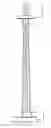
Referring to the figures, FIG. 1. is a schematic, front view of the tension positioning apparatus (10) which is generally made up of a top assembly (4) and a bottom assembly (6). The tension positioning apparatus (10) does not include the pole strips (2). The top assembly (4) and the bottom assembly (6) work in conjunction with each other from opposite sides of any attached pole strip(s) (2) in order to position, place tension upon, and hold the pole strip(s) (2) in place for pole construction.
The top assembly (4) is generally comprised of a top support (32), a tensioning device (30), a top head (26), a top clamping device (18) and a top positioning device (22). While the bottom assembly (6) is generally comprised of a bottom support (12), a bottom head (14), and a bottom clamping device (20). It is also anticipated that the bottom assembly may include a bottom positioning device (16).
The clamping devices (20 & 24) are mounted on, or in conjunction with, the positioning devices (16 & 28) if present, and the heads (14 & 26). It is anticipated that each clamping device (20 & 24) will incorporate a multiplicity of clamps (18 & 22), each removably attachable to an end of a pole strip (2) so that multiple pole strips (2) may be attached to the top and bottom assemblies (4 & 6) concurrently. The multiplicity of clamps (18 & 22) allow the pole strips (2), which are generally elongated, flat metallic strips, to be placed edge to edge in a polygonal and generally circular configuration (as shown in FIG. 3) so that the pole strips (2) may be joined to from a pole. It is generally anticipated that the poles will be polygonal and generally circular in shape, but it is anticipated that other shapes could be created as well. For example, in a certain circumstance, and air-foil shaped pole may be advantageous. Such a pole could be created using the current invention by arranging the clamps (18 & 22) in the appropriate configuration. Alternatively, the clamping devices (20 & 24) may be constructed so that a single clamping device (20 or 24) is removably attachable to multiple pole strips (2). It is anticipated that the parts of the top assembly (4) and bottom assembly (6) will be removably attached, providing for ease of repair and increased functionality. This is particularly important in regard to the clamping devices (20 & 24) which provide the structure about which the pole strips (2) will be placed and resulting poles manufactured. Thus, using different sized clamping devices (20 & 24) will result in varying sized poles being manufactured. To this end, it is further anticipated that the tension positioning device (10) will allow for either removable attachment of variably sized clamping devices (20 & 24), or clamping devices (20 & 24) that are adjustably sized. This could also be accomplished by incorporating clamping devices (20 & 24) with adjustably positioned clamps (18 & 22). Such adjustability is not a requirement of the tension positioning device (10), rather an alternative embodiment.
The top head (26) is connected to a top support (32), via a tensioning device (30). The tensioning device (30) is used to pull against the top head (26) and the top clamping device (24) such that tension is placed upon the attached pole strip(s) (2), which are likewise attached at their opposite ends to the bottom assembly (6).
The tensioning device (30) provides a means for providing tension against the pole strips (2). The are a number of means and devices that may be employed as the tensioning device (30), including without limitation, motorized devices that employ connectors such as rope, chain, cables, rods, or other like elements to attach to the top head (26), screw devices, hydraulics, counter-weights, pulley systems, levers, and like systems. The top support (32) and the bottom support (12) are capable of holding, in a generally rigid manner, the top assembly (4), bottom assembly (6), and pole strips (2) while same are under applied tension.
It is anticipated that there will be at least one positioning device associated with the tension positioning apparatus (10). Generally, it is anticipated that a top positioning device (28) will be employed, however both a top positioning device (28) and a bottom positioning device (16) may be used, or just a bottom positioning device (16). The positioning devices (28 & 16) provide generally horizontal positioning for the associated clamping device and any attached pole strip(s) (2), or more accurately horizontal movement in relation to a longitudinal axis (A-A) running from the top assembly (4), lengthwise through the pole strips (2), and through the bottom assembly (6). The positioning devices (28 & 16) may incorporate unitary movement in which the entire clamping device (20 and/or 24) moves, or the individual clamps (18 or 22) may move relative to the clamping devices (20 or 24). The positioning devices (28 & 16) may also be active or passive. A passive positioning device would employ one or more movable connection(s) between the clamping device and the support, thus allowing that assembly to move and adjust in response to active adjustments from the opposing assembly. An active positioning device would employ a device capable of mechanized movement to a position determined by the operator. It is anticipated that the positioning devices (28 & 16) could either be separate from the tensioning device (30), or that a single device could provide both functions.
The bottom head (14) is mounted to the bottom support (12), and the top head (26) is mounted to the top support (32). The heads (14 & 26) may provide passive positioning function by being movably connected to the supports (12 & 32).
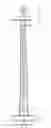
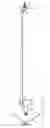
FIG. 2 is a perspective view of the tension positioning device (10) with a single pole strip (2) attached between the top assembly (4) and the bottom assembly (6). Pole strips (2) are mounted to the clamping devices (20 & 24) on the top and bottom heads (26 & 14). The top positioning device (28) (or bottom positioning device (not shown) if same is employed) is moved to adjust the final horizontal position of the pole strip (2). Once all of the pole strips (2) are in horizontal position, tension is applied by the tensioning device (30) in an outward direction along the longitudinal axis A-A, transmitting tension to the pole strips (2). When all of the pole strips (2) are tensioned and in their final position, they can be welded or otherwise joined in order to manufacture a pole.
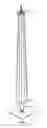
FIG. 3 is a perspective view of the tension positioning device (10) with a multiplicity of pole strips (2) attached between the top assembly (4) and the bottom assembly (6) and forming a cylindrical, pole-like structure ready for welding or other joining process. It is anticipated that poles manufactured using the tension positioning device (10) will be constructed parallel to gravitational pull, or perpendicularly to the ground, thus the top assembly (4) will be vertically oriented as to the bottom assembly (6). This orientation virtually eliminates “bowing” of the pole strips (2) that may occur when they are assembled horizontally. It is anticipated however that such vertical positioning would be unnecessary if the tension positioning device (10) was being employed to manufacture poles in a zero gravity environment.
Although the invention has been described with reference to specific embodiments, this description is not meant to be construed in a limited sense. Various modifications of the disclosed embodiments, as well as alternative embodiments of the inventions will become apparent to persons skilled in the art upon the reference to the description of the invention. It is, therefore, contemplated that the appended claims will cover such modifications that fall within the scope of the invention.
Claims
I claim:1. A tension positioning device for assembling pole strips into poles comprising:
a top assembly and a bottom assembly positioned vertically along a longitudinal axis;
said top assembly comprising a top support connected with a top clamping device;
said bottom assembly comprising a bottom support connected with a bottom clamping device; and
wherein said top clamping device and said bottom clamping device are removably attachable to one or more of said pole strips.
2. The tension positioning device of claim 1, wherein said top assembly further comprises a top positioning device connected with said top support and said top clamping device.
3. The tension positioning device of claim 1, wherein said bottom assembly further comprises a bottom positioning device connected with said bottom support and said bottom clamping device.
4. The tension positioning device of claim 1, wherein said bottom assembly further comprises a tensioning device.
5. The tension positioning device of claim 4, wherein said top assembly further comprises a top positioning device.
6. The tension positioning device of claim 4, wherein said bottom assembly further comprises a bottom positioning device.
7. The tension positioning device of claim 1, wherein said top clamping device further comprises one or more top clamps.
8. The tension positioning device of claim 7, wherein said top clamps are movably positioned on said top clamping device.
9. The tension positioning device of claim 1, wherein said bottom clamping device further comprises one or more bottom clamps.
10. The tension positioning device of claim 9, wherein said bottom clamps are movably positioned on said bottom clamping device.
11. The tension positioning device of claim 1, wherein said top clamping device is removably attached to said top assembly.
12. The tension positioning device of claim 1, wherein said bottom clamping device is removably attached to said bottom assembly.
13. The tension positioning device of claim 1, wherein:
said top assembly further comprises a top head connected with said top support and said top clamping device; and
said bottom assembly further comprises a bottom head connected with said bottom support and said bottom clamping device.
14. The tension positioning device of claim 13, wherein said top head is movably attached to said top support.
15. The tension positioning device of claim 13, wherein said bottom head is movably attached to said bottom support.
16. The tension positioning device of claim 4, wherein said tensioning devise further comprises a mechanized device incorporating one of a rope, chain, cable, rod, screw, hydraulics, pulleys, lever, or counter weight.
17. A tension positioning device for assembling pole strips into poles comprising:
a top assembly and a bottom assembly positioned along a longitudinal axis;
said top assembly comprising a top support connected with a tensioning device and a top clamping device;
said bottom assembly comprising a bottom support connected with a bottom clamping device; and
wherein said top clamping device and said bottom clamping device are removably attachable to one or more of said pole strips.
18. The tension positioning device of claim 17, wherein said top assembly further comprises a top positioning device connected with said top support, said tensioning device, and said top clamping device.
19. The tension positioning device of claim 17, wherein said bottom assembly further comprises a bottom positioning device connected with said bottom support and said bottom clamping device.
20. The tension positioning device of claim 17, wherein said longitudinal axis is parallel with gravitational pull.
21. The tension positioning device of claim 20, wherein said top assembly further comprises a top positioning device.
22. The tension positioning device of claim 20, wherein said bottom assembly further comprises a bottom positioning device.
23. The tension positioning device of claim 17, wherein said top clamping device further comprises one or more top clamps.
24. The tension positioning device of claim 23, wherein said top clamps are movably positioned on said top clamping device.
25. The tension positioning device of claim 17, wherein said bottom clamping device further comprises one or more bottom clamps.
26. The tension positioning device of claim 25, wherein said bottom clamps are movably positioned on said bottom clamping device.
27. The tension positioning device of claim 17, wherein said top clamping device is removably attached to said top assembly.
28. The tension positioning device of claim 17, wherein said bottom clamping device is removably attached to said bottom assembly.
29. The tension positioning device of claim 17, wherein:
said top assembly further comprises a top head connected with said top support, said tensioning device, and said top clamping device; and
said bottom assembly further comprises a bottom head connected with said bottom support and said bottom clamping device.
30. The tension positioning device of claim 29, wherein said top head is movably attached to said top support.
31. The tension positioning device of claim 29, wherein said bottom head is movably attached to said bottom support.
32. The tension positioning device of claim 20, wherein said tensioning devise further comprises a mechanized device incorporating one of a rope, chain, cable, rod, screw, hydraulics, pulleys, lever, or counter weight.
33. The tension positioning device of claim 20, wherein said tensioning devise uses the weight of said pole strips in order to apply tension.
34. A method of positioning and tensioning pole strips in preparation for pole manufacture comprising:
attaching opposing ends of said pole strips to a top assembly and a bottom assembly of a tension positioning device, wherein said top assembly and said bottom assembly are oriented along a longitudinal axis that is parallel with gravitational pull; and
applying tension along said longitudinal axis to said pole strips.
35. The method of claim 34 wherein:
said top assembly comprises a top support connected with a tensioning device and a top positioning device, and said method further comprises adjusting the position of said pole strips using said top positioning device.
36. The method of claim 34 wherein said applying tension step uses one of a rope, chain, cable, rod, screw, hydraulics, pulleys, lever, counter weight, or the weight of said pole strips in order to apply tension.
37. The method of claim 35 wherein said applying tension step uses one of a rope, chain, cable, rod, screw, hydraulics, pulleys, lever, counter weight, or the weight of said pole strips in order to apply tension.
38. The method of claim 34 wherein:
said bottom assembly comprises a bottom support connected with a bottom positioning device, and
said method further comprises adjusting the position of said pole strips using said bottom positioning device.
39. The method of claim 34 wherein said attaching step comprises placing said pole strips in a generally circular, polygonal configuration.
Images & Drawings included:
Sources:
- United States Patent and Trademark Office - verify current appl. status at the USPTO↗
Recent applications in this class:
- » 20240117634 2024-04-11
Studs with triangular longitudinal channels - » 20230358044 2023-11-09
Anchorage device, anchorage comprising the anchorage device and method of producing the anchorage - » 20230088085 2023-03-23
Steel Thermal Stud - » 20220403654 2022-12-22
Structural post with internal connector system - » 20220120083 2022-04-21
Structural post with internal connector system - » 20220090381 2022-03-24
Modular framing structure design and a method of using the same - » 20200308834 2020-10-01
Strut and method of using same - » 20200270865 2020-08-27
Structural element - » 20200102750 2020-04-02
Self-leveling Detachable Base - » 20200102749 2020-04-02
Apparatus for supporting overhead structure