Foot controller
US20070152508A1
2007-07-05
11/250,093
2005-10-13
✅ Patent granted
US 7,626,132 B2
2009-12-01
-
-
Kyung Lee
2026-09-02
Abstract:
A foot controller for a microsurgical system that includes a body, a switch disposed on the body, and a switch guard coupled to the body and disposed in a spaced relationship to an outer surface of the switch.
Assignee:
- Alcon, Inc. 322 🇨🇭 Hunenberg, Switzerland
Interested in similar patents?
Get notified when new applications in this technology area are published.
Classification:
A61F9/00736 » CPC main
Methods or devices for treatment of the eyes; Devices for putting-in contact lenses; Devices to correct squinting; Apparatus to guide the blind; Protective devices for the eyes, carried on the body or in the hand; Methods or devices for eye surgery Instruments for removal of intra-ocular material or intra-ocular injection, e.g. cataract instruments
H01H21/26 » CPC further
Switches operated by an operating part in the form of a pivotable member acted upon directly by a solid body, e.g. by a hand; Details; Movable parts; Contacts mounted thereon; Operating parts, e.g. handle biased to return to normal position upon removal of operating force adapted for operation by a part of the human body other than the hand, e.g. by foot
A61B2017/00973 » CPC further
Surgical instruments, devices or methods, e.g. tourniquets pedal-operated
Y10T74/20528 » CPC further
Machine element or mechanism; Control lever and linkage systems Foot operated
H02B1/24 IPC
Frameworks, boards, panels, desks, casings; Details of substations or switching arrangements Circuit arrangements for boards or switchyards
H01H35/00 IPC
Switches operated by change of a physical condition
G01M17/02 IPC
Testing of vehicles; Wheeled or endless-tracked vehicles Tyres
E01C23/00 IPC
Auxiliary devices or arrangements for constructing, repairing, reconditioning, or taking-up road or like surfaces
H01H3/14 » CPC further
Mechanisms for operating contacts; Operating parts, i.e. for operating driving mechanism by a mechanical force external to the switch adapted for operation by a part of the human body other than the hand, e.g. by foot
Description
FIELD OF THE INVENTIONThe present invention generally pertains to microsurgical systems. More particularly, but not by way of limitation, the present invention pertains to foot controllers for the operation of such systems.
DESCRIPTION OF THE RELATED ARTVarious foot controllers are used to control microsurgical systems, and particularly ophthalmic microsurgical systems. During ophthalmic surgery, a surgeon views the patient's eye through an operating microscope. To control the microsurgical system and its associated handpieces during the various portions of the surgical procedure, the surgeon must either instruct a nurse how to alter the machine settings on the surgical system, or use the foot controller to change such settings. Where possible, many surgeons prefer to use the foot controller to alter the machine settings on the surgical system, eliminating the need to converse with a nurse during the surgical procedure.
Many conventional foot controllers have a foot pedal that provides linear control of the functions of the surgical system or an associated handpiece, and a series of switches or buttons that provide binary control of such functions. Exemplary foot controllers for ophthalmic microsurgical systems are disclosed in International Publication Numbers WO 00/12037, WO 99/14648, WO 98/08442, WO 96/13845, and WO 02/01310 and U.S. Pat. Nos. 4,837,857; 4,965,417; 4,983,901; 5,091,056; 5,268,624; 5,554,894; 5,580,347; 5,635,777; 5,787,760; 5,983,749; 6,179,829; 6,639,332; and 6,659,998, all of which are incorporated herein by reference.
However, proper actuation of the pedals, buttons, and switches of conventional foot controllers can still be frustrated by certain operating room conditions, such as obstructions on or near the operating room floor like the leg of a stool or gurney or a vertical wall portion of a piece of furniture or equipment. Therefore, a need remains for an improved foot controller.
SUMMARY OF THE INVENTIONThe present invention is an improved foot controller for a microsurgical system. In one aspect, the foot controller includes a body, a switch disposed on the body, and a switch guard coupled to the body and disposed in a spaced relationship to an outer surface of the switch. The switch is capable of being actuated by a side of a user's foot in a generally horizontal direction away from the body. The switch guard insures that the switch may be fully actuated in the generally horizontal direction.
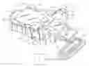
BRIEF DESCRIPTION OF THE DRAWINGSFor a more complete understanding of the present invention, and for further objects and advantages thereof, reference is made to the following description taken in conjunction with the accompanying drawing, in which FIG. 1 is a top perspective view of a foot controller of a microsurgical system according to a preferred embodiment of the present invention.
DETAILED DESCRIPTION OF THE PREFERRED EMBODIMENTSThe preferred embodiment of the present invention and its advantages are best understood by referring to FIG. 1 of the drawings, which shows a foot controller 10 electrically coupled to a microsurgical system 12 via an interface 14. Microsurgical system 12 is preferably an ophthalmic microsurgical system but may alternatively be any microsurgical system, including a system for performing optic, nasal, throat, or other surgeries. Interface 14 is preferably a cable but may alternatively be any conventional electrical interface.
Foot controller 10 preferably includes a body 16 with a base 18 that supports foot controller 10 on the operating room floor. Body 16 preferably includes a foot pedal 20, a heel rest 22, a left toe switch 24, a right toe switch 26, a left heel switch 28, a right heel switch 30, and handles 32 and 33.
Foot pedal 20 is preferably rotationally coupled to body 16 along a line 35. As shown in FIG. 1, foot pedal 20 is locked in a fully-depressed position. However, foot pedal 20 may be actuated using the upper portion of a surgeon's foot to move from a fully undepressed position (not shown) to a fully depressed position as shown in FIG. 1. Foot pedal 20 is used by the surgeon to provide proportional control to certain functions of microsurgical system 10. By way of example, depending on the operating mode of system 10, foot pedal 20 may be used to provide proportional control of vitrectomy probe cut rate, ultrasonic handpiece power, or vacuum level delivered to a handpiece.
Left toe switch 24, right toe switch 26, left heel switch 28, and right heel switch 30 are similarly used by the surgeon to switch between various modes of operation of microsurgical system 10. Left toe switch 24 is preferably a dual mode binary switch. The first mode of switch 24 is actuated when a surgeon presses downward on switch 24 with his or her toe. This first mode is referred to herein as left vertical switch 24a. The second mode of switch 24 is actuated when a surgeon presses in a generally outward, horizontal direction on switch 24 with the side of his or her foot. This second mode is referred to herein as left horizontal switch 24b. Switch 24 is preferably a momentary actuation type switch that provides tactile feedback to the user. Switch 24 is preferably constructed using two Part Number P3-30125 switches available from Otto Controls of Carpenterville, Ill., one for left vertical switch 24a, and a second for left horizontal switch 24b.
Right toe switch 26 is also a dual mode binary switch. The first mode of switch 26 is actuated when a surgeon presses downward on switch 26 with his or her toe. This first mode is referred to herein as right vertical switch 26a. The second mode of switch 26 is actuated when a surgeon presses in a generally outward, horizontal direction on switch 26 with the side of his or her foot. This second mode is referred to herein as right horizontal switch 26b. Switch 26 is preferably a momentary actuation type switch that provides tactile feedback to the user, and is preferably constructed in the same manner as switch 24.
Left heel switch 28 is preferably a binary switch that is actuated when a surgeon presses downward with his or her heel. Right heel switch 30 is a binary switch that is actuated when a surgeon presses downward with his or her heel. Switches 28 and 30 are preferably momentary actuation type switches that provide tactile feedback to the user.
Switches 28 and 30 are each preferably constructed using a Part Number P3-30125 switch available from Otto Controls of Carpenterville, Ill.
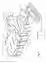
Foot controller 10 preferably also has two switch guards 34 and 36. Switch guards 34 and 36 are identical in construction. Each switch guard 34 and 36 preferably has a base member 38 coupled to body 16 and a blade member 40 coupled to base member 38 for guarding one of left toe switch 24 or right toe switch 26. Each of blade members 40 are preferably disposed in a generally parallel, spaced relationship from an outer surface 42 of left toe switch 24 and right toe switch 26. Blade members 40 are spaced a distance 44 from outer surface 42, which is greater than the actuation distance of left horizontal switch 24b and right horizontal switch 26b. In operation, switch guards 34 and 36 thus insure that a surgeon may fully actuate left horizontal switch 24b and right horizontal switch 26b regardless of any nearby obstruction on the operating room floor.
From the above, it may be appreciated that the present invention provides an improved foot controller for a microsurgical system. The present invention is illustrated herein by example, and various modifications may be made by a person of ordinary skill in the art. For example, although the present invention is described hereinabove with switch guards 34 and 36 having a particular geometry, other geometries of foot switch guards are possible as long as such geometries insure full actuation of a horizontal switch movement. As another example, although switches 24 and 26 are described hereinabove as being capable of actuation as a left horizontal switch 24b and a right horizontal switch 26b, such switches may also be actuated in a generally horizontal direction that is not exactly parallel to the operating room floor but is less than vertical actuation (perpendicular to the operating room floor).
It is believed that the operation and construction of the present invention will be apparent from the foregoing description. While the apparatus and methods shown or described above have been characterized as being preferred, various changes and modifications may be made therein without departing from the spirit and scope of the invention as defined in the following claims.
Claims
What is claimed is:1. A foot controller for a microsurgical system, comprising:
a body;
a switch disposed on said body, said switch capable of being actuated by a side of a user's foot in a generally horizontal direction away from said body;
a switch guard coupled to said body and disposed in a spaced relationship to an outer surface of said switch, said switch guard insuring that said switch may be fully actuated in said generally horizontal direction.
2. The foot controller of claim 1 wherein said switch guard is disposed in said spaced relationship at a first distance greater than a second distance that said switch may be activated in said generally horizontal direction.
3. The foot controller of claim 1 wherein said switch guard is disposed in a spaced, generally parallel relationship to said outer surface of said switch.
4. The foot controller of claim 1 wherein said switch guard comprises a base member coupled to said body and a blade member coupled to said base member for insuring that said switch may be fully actuated in said generally horizontal direction.
5. The foot controller of claim 1 wherein:
said body has a base for supporting said foot controller on a horizontal surface; and
said generally horizontal direction is a horizontal direction parallel to said horizontal surface.
6. The foot controller of claim 1 wherein said horizontal surface is a floor.
Images & Drawings included:
Sources:
- United States Patent and Trademark Office - verify current appl. status at the USPTO↗
Similar patent applications:
- » 20160032564
Multiple Control Patterns for Machines with Hand and Foot Controls - » 9681266
Remote control of a medical device using speech recognition and foot controls - » 10898088
Synchronized mid and forward motor cycle foot controls - » 10765437
Foot-controlled motorized vehicle - » 10817020
Presser foot control system - » 10308498
Foot controller for microsurgical system - » 10407639
Utility vehicle with foot-controlled mobility - » 10360756
Dual pedal foot control for hydrostatic drive - » 10740169
Foot controls for a bed - » 11035203
Wireless foot control system with optical transmitter and transceiver
Recent applications in this class:
- » 20250281327 2025-09-11
CATARACT FRAGMENTATION AND REMOVAL DEVICES AND METHODS - » 20250248844 2025-08-07
OPHTHALMIC SURGICAL PROBE - » 20250235352 2025-07-24
DEVICE AND METHOD FOR GENERATING A CHANNEL IN AN EYE TISSUE LAYER FOR TREATMENT OF OCULAR DISORDERS - » 20250235351 2025-07-24
DEVICE AND METHOD FOR GENERATING A CHANNEL IN AN EYE TISSUE LAYER FOR TREATMENT OF OCULAR DISORDERS - » 20250221851 2025-07-10
System and Method for Detection of Cornea Collapse - » 20250186255 2025-06-12
Image Processing Based Vacuum Surge Detection - » 20250152417 2025-05-15
VALVE SYSTEM OF SURGICAL CASSETTE MANIFOLD, SYSTEM, AND METHODS THEREOF - » 20250152416 2025-05-15
INTRAOCULAR DEVICE FOR DUAL INCISIONS - » 20250143924 2025-05-08
TRANSVITREAL SUBRETINAL INJECTOR - » 20250090376 2025-03-20
PNEUMATIC FOG PREVENTION FOR OPHTHALMIC LENS
Recent applications for this Assignee:
- » 20140051670 2014-02-20
Compositions containing moxifloxacin for treating otic infections - » 20110190381 2011-08-04
RNAi-mediated inhibition of frizzled related protein-1 for treatment of glaucoma - » 20110190203 2011-08-04
Ophthalmic compositions containing a synergistic combination of two polymers - » 20110178202 2011-07-21
Visible light absorbers for ophthalmic lens materials - » 20110160210 2011-06-30
CONTROL OF INTRAOCULAR PRESSURE USING ALK5 MODULATION AGENTS - » 20110144127 2011-06-16
AGENTS FOR TREATMENT OF GLAUCOMATOUS RETINOPATHY AND OPTIC NEUROPATHY - » 20110130451 2011-06-02
METHOD OF TREATING DRY EYE DISORDERS AND UVEITIS - » 20110124708 2011-05-26
RNAI-MEDIATED INHIBITION OF OCULAR HYPERTENSION TARGETS - » 20110105765 2011-05-05
UV-absorbers for ophthalmic lens materials - » 20110105453 2011-05-05
Superoxide Dismutase Mimics For The Treatment Of Optic Nerve And Retinal Damage