Device for driving light sources
US20070152605A1
2007-07-05
11/590,627
2006-10-31
✅ Patent granted
US 7,525,257 B2
2009-04-28
-
-
David Hung Vu | Tung X Le
2026-10-31
Abstract:
A driving device for driving a light source module (32) includes a first power stage circuit (30) and a first transformer circuit (31). The first transformer circuit is connected to the first power stage circuit, including a first transformer (T31), a second transformer (T32), a third transformer (T33), and a fourth transformer (T34). First inputs of primary windings of the first transformer and the fourth transformer, second inputs of primary windings of the second transformer and the third transformer are jointly connected to a positive output of the first power stage circuit, and second inputs of primary windings of the first transformer and the fourth transformer, first inputs of primary windings of the second transformer and the third transformer are jointly connected to a negative output of the first power stage circuit.
Assignee:
- HON HAI Precision Industry CO., LTD. 1,310 🇹🇼 Tu-Cheng City, Taiwan
- HON HAI PRECISION INDUSTRY CO., LTD. 2,357 🇹🇼 Tu-Cheng, Taipei Hsien, Taiwan
Interested in similar patents?
Get notified when new applications in this technology area are published.
Classification:
H05B41/245 » CPC main
Circuit arrangements or apparatus for igniting or operating discharge lamps; Circuit arrangements in which the lamp is fed by high frequency ac, or with separate oscillator frequency for a plurality of lamps
H05B41/282 » CPC further
Circuit arrangements or apparatus for igniting or operating discharge lamps; Circuit arrangements in which the lamp is fed by power derived from dc by means of a converter, e.g. by high-voltage dc using static converters with semiconductor devices
Y02B20/00 » CPC further
Energy efficient lighting technologies, e.g. halogen lamps or gas discharge lamps
Y02B20/00 » CPC further
Energy efficient lighting technologies, e.g. halogen lamps or gas discharge lamps
H05B41/16 IPC
Circuit arrangements or apparatus for igniting or operating discharge lamps; Circuit arrangements in which the lamp is fed by dc or by low-frequency ac, e.g. by 50 cycles/sec ac, or with network frequencies
Description
BACKGROUND
1. Field of the Invention
The present invention relates to electronic driving devices, and particularly to a device for driving a light source module, typically used for changing polarities of output voltages thereof.
2. Related Art
Generally, discharge lamps have been used as light sources of a liquid crystal display (LCD) panel, which need high voltage to light up the light sources. With large size LCD panels, a plurality of lamps is required for providing sufficient light intensity in the LCD panel.
FIG. 6 shows a schematic diagram of a conventional driving device connected to a light source module having a plurality of lamps L1n (n=1, 2, 3, . . . , n). The conventional driving device includes a power stage circuit 10 and a plurality of transformers T1n (n=1, 2, 3, . . . , n). Each of the transformers T1n (n=1, 2, 3, . . . , n) includes a primary winding and a secondary winding. Each of the primary windings has a first input a1n (n=1, 2, 3, . . . , n) and a second input b1n (n=1, 2, 3, . . . , n), and each of secondary windings has a high voltage terminal c1n (n=1, 2, 3, . . . , n) and a low voltage terminal d1n (n=1, 2, 3, . . . , n). The first inputs a1n (n=1, 2, 3, . . . , n) of the primary windings of the transformers T1n (n=1, 2, 3, . . . , n) are jointly connected to one output of the power stage 10. Similarly, the second inputs b1n (n=1, 2, 3, . . . , n) of the primary windings of the transformers T1n (n=1, 2, 3, . . . , n) are jointly connected to another output of the power stage 10. The high voltage terminals C1n (n=1, 2, 3, . . . , n) of the secondary winding of the transformers T1n (n=1, 2, 3, . . . , n) are respectively connected to the lamps L1n (n=1, 2, 3, . . . , n), and the low voltage terminals d1n (n=1, 2, 3, . . . , n) of the secondary winding of the transformers T1n (n=1, 2, 3, . . . , n) are grounded.
In the conventional driving device, because structures and the characteristics of the transformers T1n (n=1, 2, 3, . . . , n) are the same, and because of the connections between the transformers T1n (n=1, 2, 3, . . . , n), the power stage circuit 10 and the lamps L1n (n=1, 2, 3, . . . , n) are also the same, each transformer T1n (n=1, 2, 3, . . . , n) provides the same voltage in phase and the same voltage value to each of the lamps L1n (n=1, 2, 3, . . . , n). However, currents flowing through the lamps L1n (n=1, 2, 3, . . . , n) are unbalanced. The imbalanced currents deteriorate illumination uniformity of the LCD panel.
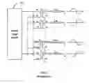
FIG. 7 shows another schematic diagram of a conventional driving device. The conventional driving device as shown in FIG. 7 is substantially the same as that of the driving device in FIG. 6, except that the first inputs a2n (n=1, 3, 5, . . . , (2n−1)) of the primary windings of the transformers T2n (n=1, 3, 5, . . . , (2n−1)) and the second inputs b2n (n=2, 4, 6, . . . , 2n) of the primary windings of the transformers T2n (n=2, 4, 6, . . . , 2n) are jointly connected to one output of the power stage circuit 20, and the second inputs b2n (n=1, 3, 5, . . . , (2n−1)) of the primary windings of the transformers T2n (n=1, 3, 5, . . . , (2n−1)) and the first inputs a2, (n=2, 4, 6, . . . , 2n) of the primary windings of the transformers T2n (n=2, 4, 6, . . . , 2n) are jointly connected to another output of the power stage circuit 20.
In the conventional driving device of FIG. 7, voltage values output from two adjacent lamps L1n (n=1, 2, 3, . . . , n) are the same magnitude, but 180 degrees out of phase. Consequently, currents flowing through the lamps L1n (n=1, 2, 3, . . . , n) are balanced such that illumination of the LCD panel is consistent. However, arcing may occur between adjacent lamps, due to high voltage differences. In order to avoid arcing, distance between the circuitries should be increased or holes formed in the circuit board.
However, increased distance between lamps, increases the size of the circuit board, and holes in the circuit board reduce physical integrity of the circuit board.
SUMMARY
One aspect of the present invention provides a driving device for driving a light source module including a first power stage circuit and a first transformer circuit. The first power stage circuit includes a positive output and a negative output. The first transformer circuit, connected to the first power stage circuit, includes a first transformer, a second transformer, a third transformer, and a fourth transformer. The first transformer includes a primary winding. The second transformer includes a primary winding. The third transformer includes a primary winding. The fourth transformer includes a primary winding. Each primary winding has a first input and a second input. The first input of the primary winding of the first transformer, the second input of the primary winding of the second transformer, the second input of the primary winding of the third transformer, and the first input of the primary winding of the fourth transformer are jointly connected to the positive output of the first power stage circuit. The second input of the primary winding of the first transformer, the first input of the primary winding of the second transformer, the first input of the primary winding of the third transformer, and the second input of the primary winding of the fourth transformer are jointly connected to the negative output of the first power stage circuit.
Another aspect of the present invention provides a driving device for driving a plurality of light source modules includes a first power stage circuit and a plurality of first transformer circuits. The first power stage circuit includes a positive output and a negative output. The first transformer circuits are connected to the first power stage circuit. Each of the first transformer circuits includes a first transformer, a second transformer, a third transformer, and a fourth transformer. The first transformer includes a primary winding. The second transformer includes a primary winding. The third transformer includes a primary winding. The fourth transformer includes a primary winding. Each of the primary windings has a first input and a second input. The first input of the primary winding of the first transformer, the second input of the primary winding of the second transformer, the second input of the primary winding of the third transformer, and the first input of the primary winding of the fourth transformer are jointly connected to the positive output of the first power stage circuit. The second input of the primary winding of the first transformer, the first input of the primary winding of the second transformer, the first input of the primary winding of the third transformer, and the second input of the primary winding of the fourth transformer are jointly connected to the negative output of the first power stage circuit.
Other advantages and novel features will become more apparent from the following detailed description when taken in conjunction with the accompanying drawings, in which:
BRIEF DESCRIPTION OF THE DRAWINGS
FIG. 1 is a schematic diagram of a driving device of a first exemplary embodiment of the present invention;
FIG. 2 is a schematic diagram of a driving device of a second exemplary embodiment of the present invention;
FIG. 3 is a schematic diagram of a driving device of a third exemplary embodiment of the present invention;
FIG. 4 a schematic diagram of is a driving device of a fourth exemplary embodiment of the present invention;
FIG. 5 is a schematic diagram of a driving device of a fifth exemplary embodiment of the present invention;
FIG. 6 is a schematic diagram of a conventional driving device; and
FIG. 7 is a schematic diagram of another conventional driving device.
DETAILED DESCRIPTION OF EMBODIMENTS
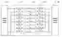
FIG. 1 is a schematic diagram of a driving device of a first exemplary embodiment of the present invention. The driving device for driving a light source module 32 includes a power stage circuit 30 and a transformer circuit 31. The power stage circuit 30 includes a positive output and a negative output. The transformer circuit 31 includes a first transformer T31, a second transformer T32, a third transformer T33, and a fourth transformer T34. The light source module 32 includes a plurality of light sources/lamps L31, L32, L33, L34.
The first transformer T31, the second transformer T32, the third transformer T33, and the fourth transformer T34 respectively includes a primary winding and a secondary winding. Each primary winding correspondingly has a first input a3n (n=1, 2, 3, 4) and a second input b3n (n=1, 2, 3, 4), and each secondary winding correspondingly has a first output c3n (c=1, 2, 3, 4) and a second output d3n (n=1, 2, 3, 4). In the exemplary embodiment, the first outputs c3n (c=1, 2, 3, 4) of the secondary windings are high voltage terminals, and the second outputs d3n (n=1, 2, 3, 4) of the secondary windings are low voltage terminals.
The first input a31 of the primary winding of the first transformer T31, the second input b32 of the primary winding of the second transformer T32, the second input b33 of the primary winding of the third transformer T33, and the first input a34 of the primary winding of the fourth transformer T34 are jointly connected to the positive output of the power stage circuit 30. The second input b31 of the primary winding of the first transformer T31, the first input a32 of the primary winding of the second transformer T32, the first input a33 of the primary winding of the third transformer T33, and the second input b34 of the primary winding of the fourth transformer T34 are jointly connected to the negative output of the power stage circuit 30.
In addition, the first outputs C3n (n=1, 2, 3, 4) of the secondary windings of the first transformer T31, the second transformer T32, the third transformer T33, and the fourth transformer T34 are respectively connected to one end of the lamps L3n (n=1, 2, 3, 4), and the second outputs d3n (n=1, 2, 3, 4) of the secondary windings of the first transformer T31, the second transformer T32, the third transformer T33, and the fourth transformer T34 are grounded. The other ends of the lamps L3n (n=1, 2, 3, 4) are also grounded.
Consequently, voltages to the lamp L31 and the lamp L34 are positive and of the same magnitude and phase. Voltages to the lamp L32 and the lamp L33 are negative and are also of the same magnitude and phase.
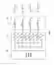
FIG. 2 is a schematic diagram of a driving device of a second exemplary embodiment of the present invention. In the exemplary embodiment, the driving device drives a plurality of light source modules 42n (n=1, 2, 3, . . . , n), and includes a power stage circuit 40, and a plurality of transformer circuits 41n (n=1, 2, 3, . . . , n). The transformer circuits 41n (n=1, 2, 3, . . . , n) have the same structures as those of the transformer circuit 31 of FIG. 1, and the transformer circuits 41n (n=1, 2, 3, . . . , n) and the light source modules 42n (n=1, 2, 3, . . . , n) have similar connections to those of the transformer circuit 31 and the light source module 32 of FIG. 1, and thus descriptions thereof are omitted.
In the exemplary embodiment, in the first transformer circuits 41n (n=1, 2, 3, . . . , n), one of the output voltage polarities, except the first or the last one, is the same as one of two adjacent output voltage polarities, and is opposite to the other one of two adjacent output voltage polarities. In the exemplary embodiment, the first and the last output voltage polarities are both positive. In alternative exemplary embodiments, the first and the last output voltage polarities are both negative.
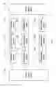
FIG. 3 is a schematic diagram of a driving device of a third exemplary embodiment of the present invention. The driving device as shown in FIG. 3 is substantially the same as that of FIG. 1, except that the light source module 52 includes a first lamp L51 and a second lamp L52, which are U-shaped lamps. One end of the first lamp L51 is connected to the first output c51 of the secondary winding of the first transformer T51, and the other end of the first lamp L51 is connected to the first output c52 of the secondary winding of the second transformer T52. One end of the second lamp L52 is connected to the first output C53 of the secondary winding of the third transformer T53, and the other end of the second lamp L52 is connected to the first output C54 of the secondary winding of the fourth transformer T54.
When the driving device drives a plurality of U-shaped lamps, the present invention is the same as that of the FIG. 2; that is, the transformer circuits 41n (n=1, 2, 3, . . . , n) and the light source modules 42n (n=1, 2, 3, . . . , n) of FIG. 2 have similar connections to those of the transformer circuit 51 and the light source module 52 of FIG. 3, and further description is omitted.
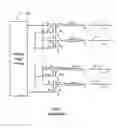
FIG. 4 is a schematic diagram of a driving device of a fourth exemplary embodiment of the present invention. The driving device includes two power stage circuits 60, 60′, two transformer circuits 61, 61′, and a light source module 62. The power stage circuit 60 and the transformer circuit 61 have similar connections to those of the power stage circuit 30 and the transformer circuit 31 as shown in FIG. 1; and the transformer circuit 61 and the light source module 62 have similar connections to those of the transformer circuit 31 and the light source module 32. Similarly, the power stage circuit 60′ and the second transformer circuit 61′ have similar connections to those of the power stage circuit 30 and the transformer circuit 31 as shown in FIG. 1; and the transformer circuit 61′ and the light source module 62 have similar connections to those of the transformer circuit 31 and the light source module 32.
The transformer 61′ includes a fifth transformer T61′, a sixth transformer T62′, a seventh transformer T63′, and an eighth transformer T64′. The first input a61′ of the primary winding of the fifth transformer T61′ is connected to a negative output of the power stage circuit 60′, and the second input b64′ of the primary winding of the eighth transformer T64′ is connected to a positive output of the power stage circuit 60′.
FIG. 5 is a schematic diagram of a driving device of a fifth exemplary embodiment of the present invention. The driving device includes two power stage circuit 70, 70′, a plurality of transformer circuits 71n (n=1, 2, 3, . . . , n), 71n′ (n=1, 2, 3, . . . n), and a plurality of light source modules 72n (n=1, 2, 3, . . . , n). The transformer circuits 71n (n=1, 2, 3, . . . , n) and 71n′ (n=1, 2, 3, . . . , n) have similar structures to those of the transformer circuit 61 and 61′ as shown in FIG. 4. The transformer circuits 71n (n=1, 2, 3, . . . , n) and the light source modules 72n (n=1, 2, 3, . . . , n) have similar connections to those of the transformer circuit 61 and the light source module 62 as shown in FIG. 4; and the light source modules 72n (n=1, 2, 3, . . . , n) and the transformer circuits 71n′ (n=1, 2, 3, . . . , n) have similar connections to those of the light source module 62 and the transformer circuit 61′.
Similarly, in the exemplary embodiment, in the transformer circuits 71n (n=1, 2, 3, . . . , n) and 71n′ (n=1, 2, 3, . . . , n), one of output voltage polarities, except the first or the last one, is the same as one of two adjacent output voltage polarities, and is opposite to the other one of two adjacent output voltage polarities.
In the exemplary embodiment, in the first transformer circuits 71n (n=1, 2, 3, . . . , n), the first and the last output voltage polarities are both positive; and in the second transformer circuits 71n′ (n=1, 2, 3, . . . , n), the first and the last output voltage the polarities are both negative. In alternative exemplary embodiments, the first and last output voltage polarities in the transformer circuits 71n (n=1, 2, 3, . . . , n) and 71n′ (n=1, 2, 3, . . . , n) can be exchanged. That is, the first and last output voltage polarities in the transformer circuits 71n (n=1, 2, 3, . . . , n) are both negative; and the first and last output voltage polarities in the transformer circuits 71n′ (n=1, 2, 3, . . . , n) are both positive.
In the present invention, output voltages polarities are arranged in an array in the transformer circuit to ensure that currents flowing through the lamps are balanced, and to ensure that voltage difference between some adjacent lamps are zero. Therefore, arcing is avoided. In addition, distance between two adjacent lamps is reduced, and thus area of a circuit board is reduced and the driving device has lower cost.
While various embodiments and methods of the present invention have been described above, it should be understood that they have been presented by way of example only and not by way of limitation. Thus the breadth and scope of the present invention should not be limited by the above-described exemplary embodiments, but should be defined only in accordance with the following claims and their equivalent.
Claims
We claim:1. A driving device for driving a light source module comprising a plurality of lamps, comprising:
a first power stage circuit, comprising a positive output and a negative output; and
a first transformer circuit, connected to the first power stage circuit, comprising:
a first transformer comprising a primary winding;
a second transformer comprising a primary winding;
a third transformer comprising a primary winding; and
a fourth transformer comprising a primary winding;
wherein each primary winding has a first input and a second input; the first input of the primary winding of the first transformer, the second input of the primary winding of the second transformer, the second input of the primary winding of the third transformer, and the first input of the primary winding of the fourth transformer are jointly connected to the positive output of the first power stage circuit; and the second input of the primary winding of the first transformer, the first input of the primary winding of the second transformer, the first input of the primary winding of the third transformer, and the second input of the primary winding of the fourth transformer are jointly connected to the negative output of the first power stage circuit.
2. The driving device as claimed in claim 1, wherein the first transformer, the second transformer, the third transformer, and the fourth transformer respectively further comprise a secondary winding, and each secondary winding has a first output and a second output.
3. The driving device as claimed in claim 2, wherein the first outputs are high voltage terminals, and the second outputs are low voltage terminals.
4. The driving device as claimed in claim 2, wherein the second outputs are grounded.
5. The driving device as claimed in claim 4, wherein one end of each lamp is respectively connected to the first output of the secondary winding of the corresponding transformer of the first transformer circuit, and the other end of each lamp is grounded.
6. The driving device as claimed in claim 4, wherein the light source module comprises a first lamp and a second lamp, one end of the first lamp is connected to the first output of the secondary winding of the first transformer, and the other end of the first lamp is connected to the first output of the secondary winding of the second transformer; one end of the second lamp is connected to the first output of the secondary winding of the third transformer, and the other end of the second lamp is connected to the first output of the secondary winding of the fourth transformer.
7. The driving device as claimed in claim 6, wherein the first lamp and the second lamp are U-shaped lamps.
8. The driving device as claimed in claim 4, further comprising:
a second power stage circuit, comprising a positive output and a negative output; and
a second transformer circuit, connected to the second power stage circuit, comprising:
a fifth transformer comprising a primary winding;
a sixth transformer comprising a primary winding;
a seventh transformer comprising a primary winding; and
an eighth transformer comprising a primary winding;
wherein each primary winding has a first input and a second input; the first input of the primary winding of the fifth transformer, the second input of the primary winding of the sixth transformer, the second input of the primary winding of the seventh transformer and the first input of the primary winding of the eighth transformer are jointly connected to the negative output of the second power stage circuit; and the second input of the primary winding of the fifth transformer, the first input of the primary winding of the sixth transformer, the first input of the primary winding of the seventh transformer and the second input of the primary winding of the eighth transformer are jointly connected to the positive output of the second power stage circuit.
9. The driving device as claimed in claim 8, wherein each lamp is connected between the first output of the secondary winding of the respective transformer of the first transformer circuit and the first output of the secondary winding of the respective transformer of the second transformer circuit.
10. A driving device for driving a plurality of light source modules, comprising:
a first power stage circuit, comprising a positive output and a negative output; and
a plurality of first transformer circuits, connected to the first power stage circuit, each of the plurality of first transformer circuits comprising:
a first transformer comprising a primary winding;
a second transformer comprising a primary winding;
a third transformer comprising a primary winding; and
a fourth transformer comprising a primary winding;
wherein each primary winding has a first input and a second input; the first input of the primary winding of the first transformer, the second input of the primary winding of the second transformer, the second input of the primary winding of the third transformer, and the first input of the primary winding of the fourth transformer are jointly connected to the positive output of the first power stage circuit; and the second input of the primary winding of the first transformer, the first input of the primary winding of the second transformer, the first input of the primary winding of the third transformer, and the second input of the primary winding of the fourth transformer are jointly connected to the negative output of the first power stage circuit.
11. The driving device as claimed in claim 10, wherein the first transformer, the second transformer, the third transformer, and the fourth transformer respectively further comprises a secondary winding, and each secondary winding has a first output and a second output.
12. The driving device as claimed in claim 11, wherein the first outputs are high voltage terminals, and the second outputs are low voltage terminals.
13. The driving device as claimed in claim 11, wherein the second outputs are grounded.
14. The driving device as claimed in claim 13, wherein one end of each lamp is connected to the output of the secondary winding of the respective transformer of the first transformer circuits, and the other end of each lamp is grounded.
15. The driving device as claimed in claim 13, wherein each light source module comprises a first lamp and a second lamp, one end of the first lamp is connected to the first output of the secondary winding of the first transformer, and the other end of the first lamp is connected to the first output of the secondary winding of the second transformer; one end of the second lamp is connected to the first output of the secondary winding of the third transformer, and the other end of the second lamp is connected to the first output of the secondary winding of the fourth transformer.
16. The driving device as claimed in claim 15, wherein the first lamp and the second lamp are U-shaped lamps.
17. The driving device as claimed in claim 13, further comprising:
a second power stage circuit, comprising a positive output and a negative output; and
a plurality of second transformer circuits, connected to the second power stage circuit, comprising:
a fifth transformer comprising a primary winding;
a sixth transformer comprising a primary winding;
a seventh transformer comprising a primary winding; and
an eighth transformer comprising a primary winding;
wherein each primary winding has a first input and a second input; the first input of the primary winding of the fifth transformer, the second input of the primary winding of the sixth transformer, the second input of the primary winding of the seventh transformer, and the first input of the primary winding of the eighth transformer are jointly connected to the negative output of the second power stage circuit; and the second input of the primary winding of the fifth transformer, the first input of the primary winding of the sixth transformer, the first input of the primary winding of the seventh transformer, and the second input of the primary winding of the eighth transformer are jointly connected to the positive output of the second power stage circuit.
18. The driving device as claimed in claim 17, wherein each lamp is connected between the first output of the secondary winding of the respective transformer of the plurality of first transformer circuits and the first output of the secondary winding of the respective transformer of the plurality of second transformer circuits.
19. An assembly comprising:
a plurality of light sources arranged side by side; and
a plurality of transformers electrically connectable to said plurality of light sources, respectively, and correspondingly arranged side by side, each of said plurality of transformers able to accept input power and transform said input power to output power for powering a corresponding one of said plurality of light sources, said each of said plurality of transformers comprising a first output thereof to electrically connect to said corresponding one of said plurality of light sources for transmitting said output power to said corresponding one of said plurality of light sources, and a second output thereof to be grounded, said output power through said first output of said each of said plurality of transformers being in a same power phase as a neighboring one of said plurality of transformers, and being in an opposite power phase to another neighboring one of said plurality of transformers.
20. The assembly as claimed in claim 19, wherein an input connection of said each of said plurality of transformers is same as an input connection of said neighboring one of said plurality of transformers, and is different from an input connection of said another neighboring one of said plurality of transformers.
Images & Drawings included:


Sources:
- United States Patent and Trademark Office - verify current appl. status at the USPTO↗
Similar patent applications:
- » 20120206427
Light source driving device, light source driving method, and image display device - » 20160323549
Light source drive device, light source drive method, and display apparatus - » 20230102951
LIGHT SOURCE DRIVING DEVICE, LIGHT SOURCE DEVICE, AND IMAGE CAPTURING DEVICE - » 20250138164
LIGHT SOURCE DRIVING DEVICE, LIGHT SOURCE DEVICE, AND DISTANCE MEASURING DEVICE - » 20090184664
Method of driving light sources, device for driving light sources, and display device having the same - » 20240155745
LIGHT SOURCE DRIVING DEVICE, LIGHT EMITTING DEVICE, AND LIGHT SOURCE DRIVING METHOD - » 20110249069
Light source driving device, and image processing device, image reading device and image forming apparatus using the light source driving device - » 20180359839
Light source driving device, lighting apparatus, and lighting control system - » 20250093481
LIGHT SOURCE DRIVING DEVICE, LIGHT EMITTING DEVICE, AND DISTANCE MEASURING DEVICE - » 20080291259
Light source driving device, light scanning device and image forming apparatus
Recent applications in this class:
- » 20110234112 2011-09-29
Lamp driving circuit - » 20100225254 2010-09-09
Cold cathode lamp, and illumination device for display device and display device provided therewith - » 20100225253 2010-09-09
Cold-cathode lamp, and display illumination device and display device therewith - » 20100194313 2010-08-05
HIGH VOLTAGE ELECTRICAL CONNECTION LINE - » 20100014336 2010-01-21
DC-AC converter and method of supplying AC power - » 20090224696 2009-09-10
Electronic ballast with higher startup voltage - » 20090033234 2009-02-05
Illuminating lamp for a display device, an illuminating device for a display device, and a display device - » 20080285321 2008-11-20
DC-AC converter and method of supplying AC power - » 20080203938 2008-08-28
Block Dimming for Hid Lamps - » 20080129227 2008-06-05
Discharge tube lighting circuit and electronic apparatus provided with the discharge tube lighting circuit
Recent applications for this Assignee:
- » 20140363586 2014-12-11
Laser-based method for growing an array of carbon nanotubes - » 20140299819 2014-10-09
Method for making a carbon nanotube film - » 20140199855 2014-07-17
Method for making a carbon nanotube film - » 20110171419 2011-07-14
Electronic element having carbon nanotubes - » 20110110535 2011-05-12
Carbon nanotube speaker - » 20110101832 2011-05-05
SECURING MECHANISM AND ELECTRONIC DEVICE ENCLOSURE USING THE SAME - » 20110096516 2011-04-28
SUPPORTING ASSEMBLY FOR PRINTED CIRCUIT BOARD - » 20110096473 2011-04-28
Electronic device - » 20110093746 2011-04-21
System and method for determining display function of BIOS error information - » 20110073276 2011-03-31
Heat dissipation system