Differential evolution design of polyphase IIR decimation filters
US20070153946A1
2007-07-05
11/614,001
2006-12-20
✅ Patent granted
US 8,111,791 B2
2012-02-07
-
-
David C. Payne | Erin File
2029-05-13
Abstract:
A method for designing a digital filter, includes: (a) selecting a predetermined number of current sets of coefficients for the digital filter; (b) selecting a metric for evaluating coefficients of the digital filter; (c) computing a metric for each current set of coefficients; (d) deriving a next set of coefficients based on a subset of the current set of coefficients; (e) computing the metric for the next set of coefficients; (f) replacing a selected one of the current set of coefficients based on comparing the metric for the next set of coefficients with the metric for the selected current set of coefficients; and (g) iterating steps (a) to (e) until a termination criterion is met. In one embodiment, the selected metric represents a desired stop band response. The next set of coefficients may be derived by adjusting a first current set of coefficients by a weighted difference between a second current set of coefficients and a third current set of coefficients. The weighted difference may be obtained by multiplying a predetermined factor to the difference between the second current set of coefficients and the third current set of coefficients. In one embodiment, a scaling is performed such that the next set of coefficients does not include a pole outside of the unit circle.
Assignee:
- SIRF TECHNOLOGY, INC. 208 🇺🇸 San Jose, CA, United States
Interested in similar patents?
Get notified when new applications in this technology area are published.
Classification:
H03H17/045 » CPC main
Networks using digital techniques; Frequency selective networks; Recursive filters with input-sampling frequency and output-delivery frequency which differ, e.g. extrapolation; Anti-aliasing characterized by the ratio between the input-sampling and output-delivery frequencies the ratio being integer where the output-delivery frequency is lower than the input sampling frequency, i.e. decimation
H03H17/0277 » CPC further
Networks using digital techniques; Frequency selective networks; Filters characterised by a particular frequency response or filtering method; Filter sets with mutual related characteristics; Polyphase filters comprising recursive filters
H04B1/10 IPC
Details of transmission systems, not covered by a single one of groups - ; Details of transmission systems not characterised by the medium used for transmission; Receivers Means associated with receiver for limiting or suppressing noise or interference
Description
CROSS-REFERENCE TO RELATED APPLICATIONSThe present application is related to and claims benefit of priority of U.S. Provisional Patent Application (“Provisional Application”), entitled “Differential Evolution Design of Polyphase IIR Decimation Filters,” Ser. No. 60/752,619, filed on Dec. 20, 2005. The Provisional Application is hereby incorporated by reference in its entirety.
BACKGROUND OF THE INVENTION1. Field of the Invention
The present invention relates to the design of an M-path, polyphase IIR decimate-by-M filter.
2. Description of the Related Art
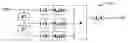
Digital M-path, polyphase infinite impulse response (IIR) filters may be used as decimators (interpolators) with a decimation (interpolation) ratio M, for M greater than one. Such filters are based on the M-tap finite impulse response (FIR) filter, in which the coefficients are replaced by allpass filters. Polyphase IIR filters provide high stop band attenuation and low pass band ripple, even with a relatively small number of coefficients.
FIG. 1 shows an example of an M-path, polyphase IIR decimate-by-M filter structure 100. As shown in FIG. 1, filter 100 receives input samples x(n), which are provided to an M-1 stage tapped delay line. Input sample x(n) and the output samples of the M-1 delay line taps are down-sampled by a factor of M (steps 101-0 to 101-(m-1)). Each of the M down-sampled values are provided as input to a corresponding one of M allpass filters 102-0 to 102-(m-1). The filtered output values are summed at summer 103; thereafter, the sum is scaled by 1/M to form the output sample y(m). The transfer function of M-path, polyphase IIR decimator 100 is given by:
H
(
z
)
=
1
M
∑
k
=
0
M
z
-
k
A
k
(
z
M
)
Assuming that each of the M allpass filters 102-0 to 102-(M-1) has N real sections (i.e. N coefficients), the transfer functions of the allpass filters 102-0 to 102-(M-1) have the form:
A
k
(
z
)
=
∏
j
=
1
N
β
k
,
j
+
z
-
1
1
+
β
k
,
j
z
-
1
Substituting the allpass filter transfer functions into the transfer function of M-path, polyphase IIR decimator 100 then gives:
H
(
z
)
=
1
M
∑
k
=
0
M
z
-
k
∏
j
=
1
N
β
k
,
j
+
z
-
M
1
+
β
k
,
j
z
-
M
Thus, the total number of filter coefficients is M×N.
According to one embodiment of the present invention, a method for designing a digital filter, includes: (a) selecting a predetermined number of current sets of coefficients for the digital filter; (b) selecting a metric for evaluating coefficients of the digital filter; (c) computing a metric for each current set of coefficients; (d) deriving a next set of coefficients based on a subset of the current set of coefficients; (e) computing the metric for the next set of coefficients; (f) replacing a selected one of the current set of coefficients based on comparing the metric for the next set of coefficients with the metric for the selected current set of coefficients; and (g) iterating steps (a) to (e) until a termination criterion is met.
In one embodiment, the selected metric represents a desired stop band response. The next set of coefficients may be derived by adjusting a first current set of coefficients by a weighted difference between a second current set of coefficients and a third current set of coefficients. The weighted difference may be obtained by multiplying a predetermined factor to the difference between the second current set of coefficients and the third current set of coefficients.
In one embodiment, a scaling is performed such that the next set of coefficients does not include a pole outside of the unit circle.
The present invention is better understood upon consideration of the detailed description below, in conjunction with the accompanying drawings.
BRIEF DESCRIPTION OF THE DRAWINGSFIG. 1 shows an example of a conventional M-path, polyphase IIR decimate-by-M filter structure 100.
FIG. 2 shows an example of 2-path, decimate-by-2 structure 200, in accordance with one embodiment of the present invention.
FIG. 3 shows an example of 3-path, decimate-by-3-structure 300, in accordance with one embodiment of the present invention.
FIG. 4 shows structure 400 of a single real section (single coefficient) of an allpass filter.
FIG. 5 shows cascading three real sections 501, 502 and 503 to form a 3-coefficient filter, in which delay elements are shared between stages.
DETAILED DESCRIPTION OF THE PREFERRED EMBODIMENTSFIG. 2 shows an example of 2-path, decimate-by-2 structure 200, and FIG. 3 shows an example of a specific 3-path, decimate-by-3-structure 300. FIG. 4 shows structure 400 of a single real section (i.e., single-coefficient) of an allpass filter. As shown in FIG. 4, input value x(n) is subtracted the output value of scale-by-beta amplifier 401, delayed by one unit. The difference is provided to scale-by-beta amplifier 401. The output value of scale-by-beta amplifier 401 is added to the input value x(n), delayed by one unit to form the filter output. As shown in FIG. 4, structure 400 has the transfer function: H ( z ) = β + z - 1 1 + β z - 1
FIG. 5 shows cascading three real sections 501, 502 and 503 to form a 3-coefficient filter, in which delay elements are shared between stages.
Lutovac and Milic1 and Krukowski and Kale2 are textbooks that provide detailed descriptions of the theory and design of N-path polyphase IIR filters, including algorithms for computing the required allpass filter coefficients. The computed coefficients are necessarily quantized to a finite number of bits in an actual implementation. Quantization by rounding or truncation may result in significant filter performance degradation (e.g., larger pass band ripple and smaller stop band attenuation). To find the best performance, given a C coefficients and B bits resolution in the quantized values, it may be necessary to evaluate all 2*B*C possible filters. Evaluation of each filter may require analyzing multiple filter responses in the pass and stop bands, and thus may quickly become computationally impractical (e.g., for an 8-bit quantization and six coefficients, there are over 1014 possible filters.)
1Miroslav D. Lutovac and Ljiljana D. Milic, “DESIGN OF HIGH-SPEED IIR FILTERS BASED ON ELLIPTIC MINIMAL Q-FACTORS PROTOTYPE”, Conference ETRAN 2002, Banja Vrucica, June 2002.
2Artur Krukowski and Izzet Kale, “DSP System Design—Complexity Reduced IIR filter Implementation for Practical Applications”, Kluwer Academic Publishers, 2003.
Conventional techniques for optimizing quantized filter coefficients include “bit-flipping” and the “Downhill Simplex Method.” (See, e.g., Chapter 3 of Krukowski and Kale). Such techniques have not been found efficient. Differential evolution (DE) is a genetic algorithm that performs direct search minimization. Stom3 describes DE in the context of digital filter design. However, Stom does not address the handling of candidate coefficient sets with poles outside of the unit circle.
3Rainer Stom, “Designing Nonstandard Filters with Differential Evolution”, IEEE SIGNAL PROCESSING MAGAZINE, Jan. 2005
In a digital filter, a pole outside of the unit circle may cause a filter to be unstable. To discard candidate coefficient sets that have poles outside the unit circle slows down the convergence of the DE algorithm. According to the present invention, these candidate coefficient sets are scaled by 1/μ times the maximum magnitude of the coefficients in that set, where μ is a number greater than 1.0. The present invention also takes advantage of the structure of the M-path polyphase decimator, which ensures that minimizing the maximum stop band magnitude response also minimizes the pass band ripple. The metric is defined as the maximum stop band magnitude response.
The MATLAB code set forth in Appendix A defines the function “NthPathNthBand_DE” which takes as inputs the values (a) “nPaths”, representing the number of paths; (b) “nc”, representing the number of sections in each path (hence, the number of coefficients); (c) “B”, the coefficient bit quantization; (d) “NP”, the number of points to use in the DE algorithm; (e) “fp”, the pass band frequency relative to sampling frequency Fs; (f) “fsb”, the stopband frequency relative to Fs; and (g) “passes”, the number of iterations for the DE algorithm. The “NthPathNthBand_DE” function output (a) “beta”, which are filter coefficients arranged in an “nPaths” by “nc” array, with ith each row corresponding to ith path; (b) “mpr”, the maximum pass band ripple (in dB); “msa”, the minimum stop band attenuation (in dB) and “pgdv”, the pass band group delay variation (in samples). Appendix B provides an example of an output filter design.
Initially, the DE algorithm randomly selects “NP” sets of B-bit coefficients, Pold. A metric is selected, which may be, for example, the maximum stop band magnitude response. This metric is computed for each of the “NP” coefficient sets. The number identifying the set with the smallest metric is stored in “bestk” and the smallest metric value is stored in “best”. The DE algorithm proceeds for “Passes” iterations. During each iteration, new sets Pnew of coefficients are initialized to the values of the old set Pold. For each of the “NP” coefficient sets, a candidate replacement set is obtained by randomly selecting a three of the existing coefficient sets (say, set numbers “rp(1)”, “rp(2)”, and “rp(3)” respectively) and computing the values of set rp(1) minus 0.85 times the values of the differences between set rp(2) and set rp(3), rounded to a “B” bit quantization. If the maximum magnitude of the coefficients in the candidate set exceeds 1.0, then the candidate set is scaled by dividing by 1.1 times that maximum magnitude, and rounded to “B” bit quantization. The candidate coefficient set replaces an existing coefficient set, if the metric of the candidate set (e.g., the maximum stop band magnitude response) is less than the metric of the existing set. After the final iteration, “beta” is set equal to the surviving coefficient set with the best metric. While the value 0.85 is selected for providing good performance, any positive number less than 1.0 may be used. Similarly, while the value 1.1 provides good performance, any value greater than 1.0 may also be used.
The MATLAB output in Appendix B is for a 3-path, decimate-by-3 decimator with 4 sections (coefficients) per path (i.e., a total of 12 coefficients). The input parameters were 8-bit coefficient quantization, pass band of 0 to 0.1Fs, stopband of 0.2Fs to 0.333Fs, 100 coefficient-point sets, and 1,000 iterations. The program required 35 seconds to run on a 3.6 GHz workstation. The transfer functions for the 12 real sections, 4 per path, are shown in both decimal fraction and hexadecimal fraction notations. The quantized coefficient decimator has maximum pass band ripple of less than 10−4 dB, minimum stop band attenuation of −48 dB, and maximum pass band group delay variation of 4.5 samples.
Thus, the present invention has been described in the context of minimizing pass band ripple while simultaneously maximizing stop band attenuation. The present invention can also provide filters with other metrics (e.g., cost functions, such as those that match arbitrary amplitude, phase, or group delay curves to frequency, or that match constrains in two or more of amplitude, phase, and group delay).
In this detailed description, the algorithms discussed carry out steps that may involve calculating, comparing, displaying or otherwise manipulating values representing physical quantities, such as electrical signals, in memory, a storage device or a display device of a computer system or another electronic computing device. The above detailed description is provided to illustrate specific embodiments of the present invention and is not intended to be limiting. Numerous variations and modifications within the scope of the present invention are possible. The present invention is set forth in the following claims.
Claims
I claim:1. A method for designing a digital filter, comprising:
(a) Selecting a predetermined number of current sets of coefficients for the digital filter;
(b) Selecting a metric for evaluating coefficients of the digital filter;
(c) Computing a metric for each current set of coefficients;
(d) Deriving a next set of coefficients based on a subset of the current set of coefficients;
(e) computing the metric for the next set of coefficients;
(f) replacing a selected one of the current set of coefficients based on comparing the metric for the next set of coefficients with the metric for the selected current set of coefficients; and
(g) iterating steps (a) to (e) until a termination criterion is met.
2. A method as in claim 1, wherein the selected metric represents a desired stop band response.
3. A method as in claim 1, wherien the next set of coefficients is derived by adjusting a first current set of coefficients by a weighted difference between a second current set of coefficients and a third current set of coefficients.
4. A method as in claim 3, wherein the weighted difference is obtained by multiplying a predetermined factor to the difference between the second current set of coefficients and the third current set of coefficients.
5. A method as in claim 4, wherein the predetermined factor is less than 1.0.
6. A method as in claim 3, further comprising scaling the next set of coefficients each by a predetermined factor.
7. A method as in claim 3, wherein the predetermined factor is selected such that none of the next set of coefficients exceed 1.0 after the scaling.
8. A method as in claim 1, wherein the precision of the current sets of coefficients and the next set of coefficients is limited by a predetermined number of bits.
9. A method as in claim 1, wherein the digital filter comprises a N-path, polyphase IIR decimation filter.
Images & Drawings included:


Sources:
- United States Patent and Trademark Office - verify current appl. status at the USPTO↗
Recent applications in this class:
- » 20220224313 2022-07-14
SYSTEM AND METHOD FOR OPTIMIZING SIGNAL PROCESSING AND STORAGE USING FREQUENCY-TIME DOMAIN CONVERSION - » 20200382104 2020-12-03
Low power lattice wave filter systems and methods - » 20090319260 2009-12-24
METHOD AND SYSTEM FOR AUDIO TRANSMIT PROCESSING IN AN AUDIO CODEC - » 20090080581 2009-03-26
TIME SEQUENTIAL PROCESSING OPERATIONS
Recent applications for this Assignee:
- » 20130072122 2013-03-21
SYSTEMS AND METHODS FOR CHANNEL PAIRING A TRANSMITTER AND A RECEIVER - » 20130021202 2013-01-24
Systems and methods of communication in an assisted navigation system - » 20120274427 2012-11-01
Auto-tuning system for an On-Chip RF filter - » 20120191614 2012-07-26
System for location based transaction security - » 20120182183 2012-07-19
Differentially coherent strobe correlator - » 20120007572 2012-01-12
Auto cascode buck voltage converter - » 20110316741 2011-12-29
Control and features for satellite positioning system receivers - » 20110312336 2011-12-22
Satellite based positioning method and system for coarse location positioning - » 20110279318 2011-11-17
Method and apparatus for a GPS receiver capable of reception of GPS signals and binary offset carrier signals - » 20110275341 2011-11-10
IP2 calibration measurement and signal generation