Ceramic matrix laminates
US20070172639A1
2007-07-26
11/654,302
2007-01-17
✅ Patent granted
US 8,182,905 B2
2012-05-22
-
-
David Sample | Lawrence Ferguson
2029-10-07
Abstract:
The invention provides systems and methods for forming low density ceramic felt material cores which are sandwiched between ceramic matrix composites to form a ceramic matrix laminate possessing a high strength-to-density ratio while maintaining a stiffness required for mechanical applications. The core and face plates are coupled together using a chemical vapor process.
Assignee:
- UNITED TECHNOLOGIES CORPORATION 4,046 🇺🇸 Hartford, CT, United States
Interested in similar patents?
Get notified when new applications in this technology area are published.
Classification:
B32B18/00 » CPC main
Layered products essentially comprising ceramics, e.g. refractory products
B82Y30/00 » CPC further
Nanotechnology for materials or surface science, e.g. nanocomposites
C04B35/565 » CPC further
Shaped ceramic products characterised by their composition ; Ceramics compositions ; Processing powders of inorganic compounds preparatory to the manufacturing of ceramic products based on non-oxide ceramics based on carbides or oxycarbides based on silicon carbide
C04B35/62281 » CPC further
Shaped ceramic products characterised by their composition ; Ceramics compositions ; Processing powders of inorganic compounds preparatory to the manufacturing of ceramic products; Forming processes; Processing powders of inorganic compounds preparatory to the manufacturing of ceramic products obtaining fibres based on non-oxide ceramics; Fibres based on carbides based on silicon carbide
C04B35/80 » CPC further
Shaped ceramic products characterised by their composition ; Ceramics compositions ; Processing powders of inorganic compounds preparatory to the manufacturing of ceramic products; Ceramic products containing macroscopic reinforcing agents containing non-metallic materials Fibres, filaments, whiskers, platelets, or the like
C04B2235/483 » CPC further
Aspects relating to ceramic starting mixtures or sintered ceramic products; Composition of constituents of the starting material or of secondary phases of the final product; Constituents and secondary phases not being of a fibrous nature; Organic compounds becoming part of a ceramic after heat treatment, e.g. carbonising phenol resins Si-containing organic compounds, e.g. silicone resins, (poly)silanes, (poly)siloxanes or (poly)silazanes
C04B2235/5284 » CPC further
Aspects relating to ceramic starting mixtures or sintered ceramic products; Composition of constituents of the starting material or of secondary phases of the final product; Constituents or additives of the starting mixture chosen for their shape or used because of their shape or their physical appearance; Constituents or additives characterised by their shapes Hollow fibers, e.g. nanotubes
C04B2235/614 » CPC further
Aspects relating to ceramic starting mixtures or sintered ceramic products; Aspects relating to the preparation, properties or mechanical treatment of green bodies or pre-forms Gas infiltration of green bodies or pre-forms
C04B2235/656 » CPC further
Aspects relating to ceramic starting mixtures or sintered ceramic products; Aspects relating to heat treatments of ceramic bodies such as green ceramics or pre-sintered ceramics, e.g. burning, sintering or melting processes characterised by specific heating conditions during heat treatment
C04B2235/6567 » CPC further
Aspects relating to ceramic starting mixtures or sintered ceramic products; Aspects relating to heat treatments of ceramic bodies such as green ceramics or pre-sintered ceramics, e.g. burning, sintering or melting processes characterised by specific heating conditions during heat treatment Treatment time
C04B2235/6583 » CPC further
Aspects relating to ceramic starting mixtures or sintered ceramic products; Aspects relating to heat treatments of ceramic bodies such as green ceramics or pre-sintered ceramics, e.g. burning, sintering or melting processes; Atmosphere during thermal treatment Oxygen containing atmosphere, e.g. with changing oxygen pressures
C04B2235/663 » CPC further
Aspects relating to ceramic starting mixtures or sintered ceramic products; Aspects relating to heat treatments of ceramic bodies such as green ceramics or pre-sintered ceramics, e.g. burning, sintering or melting processes; Specific sintering techniques, e.g. centrifugal sintering; Multi-step sintering; Annealing after sintering Oxidative annealing
C04B2235/77 » CPC further
Aspects relating to ceramic starting mixtures or sintered ceramic products; Aspects relating to sintered or melt-casted ceramic products; Physical characteristics Density
C04B2235/96 » CPC further
Aspects relating to ceramic starting mixtures or sintered ceramic products; Aspects relating to sintered or melt-casted ceramic products Properties of ceramic products, e.g. mechanical properties such as strength, toughness, wear resistance
C04B2237/361 » CPC further
Aspects relating to ceramic laminates or to joining of ceramic articles with other articles by heating; Composition of layers of ceramic laminates or of ceramic or metallic articles to be joined by heating, e.g. Si substrates; Ceramic; Non-oxidic Boron nitride
C04B2237/363 » CPC further
Aspects relating to ceramic laminates or to joining of ceramic articles with other articles by heating; Composition of layers of ceramic laminates or of ceramic or metallic articles to be joined by heating, e.g. Si substrates; Ceramic; Non-oxidic Carbon
C04B2237/365 » CPC further
Aspects relating to ceramic laminates or to joining of ceramic articles with other articles by heating; Composition of layers of ceramic laminates or of ceramic or metallic articles to be joined by heating, e.g. Si substrates; Ceramic; Non-oxidic Silicon carbide
C04B2237/38 » CPC further
Aspects relating to ceramic laminates or to joining of ceramic articles with other articles by heating; Composition of layers of ceramic laminates or of ceramic or metallic articles to be joined by heating, e.g. Si substrates; Ceramic Fiber or whisker reinforced
C04B2237/50 » CPC further
Aspects relating to ceramic laminates or to joining of ceramic articles with other articles by heating Processing aspects relating to ceramic laminates or to the joining of ceramic articles with other articles by heating
C04B2237/584 » CPC further
Aspects relating to ceramic laminates or to joining of ceramic articles with other articles by heating; Processing aspects relating to ceramic laminates or to the joining of ceramic articles with other articles by heating; Forming a gradient in composition or in properties across the laminate or the joined articles by joining layers or articles of the same composition but having different additives the different additives being fibers or whiskers
C04B2237/704 » CPC further
Aspects relating to ceramic laminates or to joining of ceramic articles with other articles by heating; Processing aspects relating to ceramic laminates or to the joining of ceramic articles with other articles by heating; Forming laminates or joined articles comprising layers of a specific, unusual thickness of one or more of the ceramic layers or articles
Y10T428/24942 » CPC further
Stock material or miscellaneous articles; Structurally defined web or sheet [e.g., overall dimension, etc.] including components having same physical characteristic in differing degree
Y10T428/249956 » CPC further
Stock material or miscellaneous articles; Web or sheet containing structurally defined element or component; Composite having voids in a component [e.g., porous, cellular, etc.]; Void-containing component partially impregnated with adjacent component Void-containing component is inorganic
Y10T428/249957 » CPC further
Stock material or miscellaneous articles; Web or sheet containing structurally defined element or component; Composite having voids in a component [e.g., porous, cellular, etc.]; Void-containing component partially impregnated with adjacent component; Void-containing component is inorganic Inorganic impregnant
Y10T428/249962 » CPC further
Stock material or miscellaneous articles; Web or sheet containing structurally defined element or component; Composite having voids in a component [e.g., porous, cellular, etc.] Void-containing component has a continuous matrix of fibers only [e.g., porous paper, etc.]
Y10T428/31504 » CPC further
Stock material or miscellaneous articles Composite [nonstructural laminate]
B32B3/06 IPC
Layered products comprising a layer with external or internal discontinuities or unevennesses, or a layer of non-planar form ; Layered products having particular features of form characterised by features of form at particular places, e.g. in edge regions for securing layers together; for attaching the product to another member, e.g. to a support, or to another product, e.g. groove/tongue, interlocking
B32B5/14 IPC
Layered products characterised by the non- homogeneity or physical structure, i.e. comprising a fibrous, filamentary, particulate or foam layer; Layered products characterised by having a layer differing constitutionally or physically in different parts characterised by a layer differing constitutionally or physically in different parts, e.g. denser near its faces
B32B5/24 IPC
Layered products characterised by the non- homogeneity or physical structure, i.e. comprising a fibrous, filamentary, particulate or foam layer; Layered products characterised by having a layer differing constitutionally or physically in different parts characterised by the presence of two or more layers which are next to each other and are fibrous, filamentary, formed of particles or foamed one layer being a fibrous or filamentary layer
B32B7/02 IPC
Layered products characterised by the relation between layers; Layered products characterised by the relative orientation of features between layers, or by the relative values of a measurable parameter between layers, i.e. products comprising layers having different physical, chemical or physicochemical properties; Layered products characterised by the interconnection of layers Physical, chemical or physicochemical properties
Description
REFERENCE TO RELATED APPLICATION
This application claims the benefit of U.S. Provisional Application No. 60/760,990, filed on Jan. 20, 2006, which is incorporated herein by reference in its entirety.
BACKGROUND OF THE INVENTION
The invention relates generally to the field of ceramic matrix laminates. More specifically, embodiments of the invention relate to systems and methods for fabricating low density ceramic felt core materials which are sandwiched between two ceramic matrix composites (CMCs).
Sandwich structures are materials that consist of two thin load-bearing face plates joined to a thicker, but less-dense core material. Loads are carried by the face plates with the core acting as a load transfer medium. Depending on the application, the face plates may be fabricated from metal, plywood or fiber reinforced composites. The core may be fabricated from a hard foam or honeycomb material, or a rigid lightweight material.
Sandwich structures are commonly employed as building materials where a high strength to density is required, and are also often used in the aircraft industry. In addition to a high strength to density ratio, the sandwich structure should also possess a high load carrying capability and resistance to torsion. For a sandwich structure functioning as a structural material in a hot section of an aircraft engine, the material must also have good resistance to oxidation, together with high strength and toughness at elevated temperatures.
One problem with the fabrication of a sandwich type structure is forming a high-quality bond between the face plates and the core material. If the bond between the face plates is weak, the material will fail in shear and not support the full load from the face plates. In many structures, the face plates are joined to the core by use of adhesives. In sandwich structures employed for high-temperature applications, the use of adhesives to bond the face plates to the core material may lead to debonding of the face plates from the core due to different coefficients of thermal expansion among the materials. In addition, most high temperature glues shrink, outgas, and crack when heated to the application temperature. This ultimately results in a weak or failed bond.
Although there are various systems and methods of constructing ceramic matrix laminates, such systems and methods are not completely satisfactory. Therefore, improved systems and methods of constructing ceramic matrix laminates are desirable.
SUMMARY OF THE INVENTION
The inventor has discovered systems and methods for fabricating a ceramic matrix laminate (CML) using a ceramic felt core between two ceramic matrix composite (CMC) face plates coupled together using a chemical vapor process. Variants of the methods can be in-situ, where the core is fabricated and the density of the CMC face plates is increased at the same time, or where CMC face plates are infiltrated with a prefabricated core.
One aspect of the invention provides methods for fabricating a ceramic matrix laminate. Methods according to this aspect of the invention preferably start with forming a preform comprising providing a core substrate, providing a first and a second face plate precursor, disposing the core substrate between the first and the second face plate precursors, attaching the core substrate to the first and the second face plate precursors, and infiltrating the preform.
Another aspect of the method is applying a compression assembly about the preform before infiltrating the preform.
Yet another aspect of the invention is a ceramic matrix laminate. Ceramic matrix laminates according to this aspect of the invention comprise a first and a second face plate, the first face plate having a density and the second face plate having a density, a core material having a density, the core material being disposed between the first and the second face plates, and the core material being coupled to the first and the second face plate using a chemical vapor process.
Another aspect of the invention provides methods for fabricating a hollow core material. Methods according to this aspect of the invention preferably start with providing a core substrate, applying a compression assembly about the core substrate, infiltrating the compression assembly with the core substrate, removing the compression assembly from the core substrate after infiltrating and oxidizing the core substrate after infiltration.
Other embodiments and advantages of the methods and systems will become apparent to those skilled in the art after reading the detailed description of the preferred embodiments.
BRIEF DESCRIPTION OF THE DRAWINGS
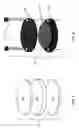
FIG. 1 is an exemplary exploded perspective view of a core preform.
FIG. 2 is a block diagram of an exemplary lamination method according to the invention.
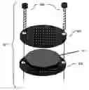
FIG. 3 is an exemplary exploded perspective view of a laminate compressing assembly.
FIG. 4 is a block diagram of an exemplary compression lamination method according to the invention.
FIG. 5 is a photomicrograph of a CML produced according to the invention wherein the top and bottom face plates are ceramic matrix composites and the middle area is the core. (magnification ˜50×)
FIG. 6 is a block diagram of an exemplary core prefabrication method according to the invention.
FIG. 7 is a photomicrograph of a fractured end of an SiC coated carbon fiber after oxidation according to the invention.
DETAILED DESCRIPTION
Embodiments of the invention will be described with reference to the accompanying figures wherein like numbers represent like elements throughout. Further, it is to be understood that the phraseology and terminology used herein is for the purpose of description and should not be regarded as limiting. The use of “including,” “comprising,” or “having” and variations thereof herein is meant to encompass the items listed thereafter and equivalents thereof as well as additional items. The terms “mounted,” “connected,” and “coupled” are used broadly and encompass both direct and indirect mounting, connecting, and coupling. Further, “connected” and “coupled” are not restricted to physical or mechanical connections or couplings.
Embodiments of the invention provide systems and methods for forming low density ceramic felt material cores which are sandwiched between two CMCs to form a CML possessing a high strength-to-density ratio while maintaining a stiffness required for mechanical applications. The CML has structural advantages similar to honeycomb-core polymer composites or metal materials, but surpasses these materials by having the ability to survive high temperature environments.
Fiber reinforced CMC imbues the CML with high-strength and toughness, and the ceramic fiber felt core provides low density. The resulting CMLs have varied applications such as heat exchangers, heat shields, engine parts, acoustic liners, furnace insulation, firewalls, etc. Table 1 shows some of the uses for these materials.
| TABLE 1 | |||
| Likely Industrial | |||
| Product Area | Examples | Market | |
| advanced heat engines | combustors, | high temperature gas | |
| liners, wear | turbines and diesel | ||
| parts | engines | ||
| heat recovery | air | energy-intensive | |
| equipment | preheaters, | industry processes | |
| recuperators | (e.g. aluminum | ||
| remelters, steel | |||
| reheaters, etc.) | |||
| burners and | radiant tube | high temperature | |
| combustors | burners | heating and/or | |
| controlled atmosphere | |||
| heating, melting | |||
| equipment | |||
| process equipment | reformers, | chemical processing | |
| reactors | equip. petroleum | ||
| refining | |||
| waste incinerator | handling, | toxic/hazardous waste | |
| systems | internals | facilities | |
| separation/filtration | filters, | gas turbine, diesel | |
| systems | substrates, | exhausts | |
| molten metal | |||
| filters | |||
| refractories | furnace | high temperature | |
| linings, | heating/melting/heat | ||
| crucibles | treating equip. | ||
| etc. | |||
| structural components | beams, | fire equip., missile | |
| panels, | protection, major | ||
| decking, | infrastructure | ||
| containers | applications | ||
The invention also provides a method for fabricating a rigidized hollow fiber core. The hollow fiber core reduces the density of the resulting CML.
The rigidized hollow fiber core may be used as an alternative for aluminum and titanium honeycomb cores that are presently used in polymer matrix composites (PMC). Their light weight, high-temperature resistance and tailorable compression strength makes them good candidates for applications in PMC structures.
The invention employs a low cost, carbon fiber felt material, such as CH grade available from Fiber Materials, Inc., or Graphite WDF felt, from National Specialty Products, for use as a substrate to fabricate a core. The material has fibers oriented in a “z” direction—perpendicular to core length (x) and width (y). The “z” fibers act as pillars, increasing the compressive strength of the core.
The ability to create hollow fibers and to control core and CMC pore size is important in the fabrication of separators or filters for use in high-temperature and/or highly corrosive environments.
To control pore size and distribution in the core material as well as the CMC, the invention may employ chemical vapor infiltration (CVI) or chemical vapor deposition (CVD). The CVD and CVI process are similar and are often used interchangeably. CVD is a process where a solid is deposited from a vapor phase. CVI is a process where a pore filling solid is deposited from a vapor phase. CVI is usually performed at lower flow rates for longer periods of time and often at lower pressures. CVI allows the microstructure and macrostructure of the CML to be tailored to a specific need by varying infiltration time and pressure. The use of CVI offers the ability to fabricate ceramic materials comprised of carbon, borides, carbides, nitrides, oxides, silicides, sulfides, beryllides, selenides, tellurides, intermetallic compounds or alloys. CVI is a non-line-of-sight coating process which is ideal for coating the core material. CVI also offers the ability to simultaneously fabricate the core and couple the core with the CMC, thereby forming a CML.
Using CVI to fabricate a core, followed by coating and coupling CMC face plates to the prefabricated core allows for modifications to be made in the core structure before coupling the CMC face plates thereto. For example, air passages may be incorporated in the core by fabricating a core first, and then laser drilling holes therein to provide cooling passages. Face plates could then be coupled to the core for CML applications such as turbine blades. The face plates of the CML may also be similarly perforated for cooling and acoustic absorption applications.
In embodiments, the core may be fabricated from the same material as the CMC matrix. Matching the material compositions minimizes thermal expansion differences between adjacent materials (i.e., between the core 103 and the CMC face plates 105).
Shown in FIG. 1 is a CML preform 101 according to the invention. The preform 101 comprises a carbon fiber felt core 103 and two CMC face plates 105.
The precursor for the CMC face plates 105 may be a fibrous material such as Nicalon. The face plate material may have more than one ply. Typically, the ceramic cloth may be first coated with boron nitride (BN) in a CVI process to provide an interface in between the matrix and the fibers. This interface is often required for proper CMC mechanical properties. The two face plates may be assembled in any suitable manner, such as in a 0°/90° lay-up.
An in situ method for fabricating a CML is shown in FIG. 2. A core 103 is provided (step 205) in a size or shape suitable for a particular part, size, application, or other purpose. Top and bottom face plates 105 are similarly provided for a top and a bottom surface of the CML (step 210). The CMC face plates 105 are attached to the top and bottom surfaces of the core substrate 103 by sewing (preferably using Nicalon yarn), stapling, gluing, compressing, or other attaching methods to form a preform (step 215). The preform 101 is then placed in a reactor and infiltrated (step 220).
Infiltration (step 220) may comprise infiltrating the core material with SiC to bond the core with the CMC using either a force-flow isothermal CVI process or an isobaric-isothermal CVI process. Both CVI processes employ hydrogen and methyltrichlorosilane (MTS) to produce SiC, and both CVI processes achieve the same infiltration result, but they have different infiltration times and different set-up complexities. In a force-flow isothermal CVI process, the precursors are forced through the preform by use of a pressure gradient. A seal or gasket is needed to prevent the reagents from passing around the object to be coated, thereby making it difficult to infiltrate complex shapes. In the isobaric-isothermal CVI process (conventional CVD), the precursors are allowed to flow around the preform. The gasses must diffuse into the preform to deposit the coating requiring a longer period of time. This isobaric-isothermal CVI process is easier to set-up and is the method preferred by industry. The force-flow isothermal process is faster than the isobaric-isothermal process, and may be more desirable in embodiments.
During the CVI process, reactant gases are formed, for example, by bubbling ultra-high purity hydrogen gas through methyltrichlorosilane (MTS) to form SiC at a flow rate of about 200 SCFM. The gas enters the reaction chamber (reactor) at room temperature and is heated to about 1,100° C. as it approaches the deposition surface. Infiltration is typically performed for approximately 24 to 48 hours.
During the infiltration period, SiC atoms are distributed throughout the reactor and permeate the core material. The SiC atoms coat the individual graphite fibers within the core substrate growing outwards and where the fibers touch each other, form a unitary SiC structure. The SiC coating thickness, and therefore density, depends upon the infiltration time and pressure. A longer infiltration period increases coating thickness, increasing density. With increased density, pore size is reduced along with distribution due to the SiC coating restricting the inner voids or passages.
After infiltration, the CML is removed from the reactor (step 235). The best coupling between the face plates 105 and core 103 is located closest to where the layers are fastened together prior to infiltration. In embodiments, the resulting CML may be used, or it may be returned to the reactor for a post-processing infiltration for further densification (optional steps 240 and 245). The result is a CML.
For greater adhesion, compressing the preform 101 together during infiltration produces a CML exhibiting uniform coupling over all mating surfaces. Shown in FIG. 3 is a compression assembly 301. The compression assembly 301 comprises two perforated graphite plates 303 and at least two graphite fasteners (bolts, clamps, clips, and others) 305 for coupling the graphite plates together. The assembly 301 applies a uniform pressure over the top and bottom surfaces of the preform 101.
A method of using the compression assembly 301 is shown in FIG. 4. The preform 101 (steps 405, 410, 415) is placed between the two perforated graphite plates 303. Grafoil may be placed between the graphite plates and the preform to minimize SiC growth between the preform and graphite plates. The preform 101 is uniformly compressed using the compression assembly 301 (step 420).
The compression assembly 301 (with preform 101) is placed in a reactor and infiltrated with SiC (step 425). SiC may be infiltrated into the CMC and core using a force-flow isothermal CVI process or an isobaric-isothermal CVI process depending on available infiltration time.
After partial infiltration, the preform 101 with compression assembly 301 is removed from the reactor (step 430) and the compression assembly 301 is removed (step 440). The resulting CML may be used, or returned to the reactor for a post-processing infiltration for further densification (optional steps 445 and 450). The result is a CML.
FIG. 5 shows a photomicrograph of a CML fabricated according to the invention. The CMC appears as two lighter areas 501, 503 (having a 0°/90° lay-up) over the darker C/SiC core 505. For this CML, the bulk density was approximately 1.8 g/cm3 (0.065 lb/in3). The density of the Nicalon mats used in the CMCs was approximately 2.55 g/cm3.
For the method shown in FIG. 6, core materials are prefabricated by coating the core fibers with SiC before the core is assembled into a CML preform. As an example, a 3″ by 0.25″ circular piece of core substrate having a density of 0.080 g/cm3 was placed between two 0.251″ thick perforated graphite plates 303 (step 605). The graphite plates 303 were coupled together thereby compressing the core material before infiltration began (step 610). The core material (with graphite plates) was then coated with SiC (step 615) using CVD. SiC was coated onto the core substrate fibers by passing hydrogen through MTS at a rate of approximately 1,000 cm3/min for approximately 1.5 hours at approximately 1,013° C.
The core material with graphite plates 303 was then removed from the reactor (step 620) and inverted (step 625). Infiltration was then resumed for approximately 45 minutes (step 630). Then, the infiltrated inverted core was removed (step 635). The bulk density of this SiC coated graphite core was approximately 0.266 g/cm3 (16.605 lb/ft3). Using this method for fabricating cores, cores may have bulk densities ranging from about 14 lb/ft3 to about 150 lb/ft3. Thereafter, the infiltrated core may be joined between two CMCs in any suitable manner to create a CML. The CMC face plates may be coupled to the fabricated core using CVD, or by using a preceramic inorganic polymer. If the face plates are coupled to the core using CVD, the core will receive another infiltration of SiC during the process thereby increasing the density of the core. If the core is adhered to the CMC face plates using a preceramic inorganic polymer, the bond between the core and CMC face plates may be weaker, which may cause the CML to fail in shear. Some exemplary preceramic inorganic polymers that may be used for coupling a core to CMC face plates include Starfire Systems, Incorporated SiC ceramic precursor resin, or KiON Corporation CERACET polysilazane silicon nitride (Si3N4) ceramic precursor resin.
In alternate embodiments, before the infiltrated core is joined between two CMCs to form a CML, it may be desirable to oxidize the carbon fiber out of the core to yield hollow SiC fibers in the core (step 640). The carbon may be oxidized out of the SiC coated core by placing the core (with or without graphite plates) in an air furnace set at approximately 1,149° C. (2,100° F.) for approximately 20 hours. Carbon will burn in air fairly rapidly at 800° C. Furnace temperatures much greater than that may not be necessary. When the SiC coated core-stops losing weight, the oxidation removal process is complete.
Shown in FIG. 7 is a scanning electron microscopy (SEM) image of a fractured, oxidized fiber. Analysis of the heat-treated core shows that the carbon substrate has been fully oxidized leaving hollow SiC fibers. The remaining foam consists of hollow SiC fibers having an average inner diameter of about 10 μm and a wall thickness of about 2 μm. The loss of the internal core of each fiber further decreases the density of the core, which in turn lowers the overall density of the fabricated CML.
A 2.56″×0.25″×0.28″ specimen was cut from a 3″ circular CML fabricated by the method of FIG. 4. This specimen was subjected to a three-point short beam shear test. The bulk density of the CML was approximately 1.8 g/cm3 (0.065 lb/in3). The results of the bend test show that the laminate failed in the top face plate while undergoing tension. The strength of the face plate was found to be approximately 18.3 Ksi. This type of failure mode is desired for laminate structures.
The core material fabricated by the method of FIG. 6 achieved a shear stress of approximately 800 psi without failure, while existing materials showed a failure in shear stress at approximately 100 psi. These results indicate that the materials of this invention have an eight time increase in shear stress over existing materials.
Table 2 shows the results of compression testing oxidized and non-oxidized SiC core materials.
| TABLE 2 | ||||
| Total time | ||||
| of | ||||
| infiltration | ρ | Brittle crushing | ||
| (hours) | (g/cm3) | Oxidized | strength (MPa) | |
| 12 | 0.331 | Yes | 1.95 | |
| 0.408 | No | 3.55 | ||
| 24 | 0.686 | Yes | 8.73 | |
| 0.709 | No | 9.80 | ||
| 36 | 0.925 | Yes | 12.7 | |
The table shows that there is a linear relationship between density and crushing strength. The measured brittle crushing strength to density ratio was slightly higher for the non-oxidized cores than for the oxidized cores.
The method of FIG. 4 may be varied by providing (at step 405) a prefabricated SiC coated hollow core as described in FIG. 6 (after step 640), if desired. In this manner, the core density and porosity may be tailored for a specific application requirement during fabrication of the core, prior to fabrication of the CML.
Table 3 shows a comparison between different lightweight core sandwich structures and the structure of the invention.
| TABLE 3 | |||
| Types of laminates | Temperature | Disadvantages | |
| polymer/honeycomb | to 600° F. | temperature | |
| limited | |||
| carbon/carbon/foam | to 2,000° F. | requires | |
| core | oxidation | ||
| protection | |||
| SiC foam/bonded | to 2,000° F. | shear | |
| core | strength | ||
| limited | |||
| SiC | to 2,000° F. | none of the | |
| felt/welded-core | above | ||
| (This invention) | |||
Cores having bulk densities ranging from about 0.268 to 1.007 g/cm3 were fabricated by various methods of this invention and they were found to have robust mechanical properties. The cores that were tested were all fabricated by a conventional CVI process (isothermal-isobaric). A laminate structure was fabricated according to the method of FIG. 6 and was found to have a high section modulus in bending and very high stiffness to weight ratios.
Although the invention herein has been described with reference to particular embodiments, it is to be understood that these embodiments are merely illustrative of the principles and applications of the present invention. It is therefore to be understood that numerous modifications may be made to the illustrative embodiments such as using one face plate for the laminate and that other arrangements may be devised without departing from the spirit and scope of the present invention as defined by the appended claims.
Claims
What is claimed is:1. A ceramic matrix laminate comprising:
a first and a second face plate, the first face plate having a density and the second face plate having a density;
a core material having a density, the core material being disposed between the first and second face plates; and
the core material being coupled to the first and second face plates using a chemical vapor process.
2. The laminate according to claim 1 wherein the core material density is less than the first face plate density and the second face plate density, and wherein the core material density is about 0.2 g/cm3 to about 2.0 g/cm3, the first face plate density is about 1.9 g/cm3 to about 2.5 g/cm3, and the second face plate density is about 1.9 g/cm3 to about 2.5 g/cm3.
3. The laminate according to claim 2 wherein the core material comprises an open cell foam.
4. A ceramic matrix laminate comprising:
a first and a second face plate, the first face plate having a density and the second face plate having a density;
a prefabricated core material having a density, the core material being disposed between the first and second face plates; and
the core material being coupled to the first and second face plates using a chemical vapor process.
5. The laminate according to claim 4 wherein the prefabricated core material density is in a range of about 0.2 g/cm3 to about 1.0 g/cm3, and the prefabricated core material density is less than the first face plate density and the second face plate density.
6. The laminate according to claim 5 wherein the prefabricated core material comprises graphite fibers coated with SiC.
7. The laminate according to claim 5 wherein the prefabricated core material comprises hollow SiC fibers.
8. A method of fabricating a ceramic matrix laminate comprising:
forming a preform comprising:
providing a core substrate;
providing a face plate precursor;
disposing the core substrate on one side of the face plate precursor;
coupling the core substrate to the face plate precursor; and
infiltrating the preform.
9. A method of fabricating a ceramic matrix laminate comprising:
forming a preform comprising:
providing a core substrate;
providing a first and a second face plate precursor;
disposing the core substrate between the first and second face plate precursors;
coupling the core substrate to the first and second face plate precursors; and
infiltrating the preform.
10. The method according to claim 9 wherein infiltrating comprises infiltrating SiC through the preform.
11. The method according to claim 10 further comprising applying a compression assembly about the preform before infiltrating the preform.
12. A method of fabricating a core material comprising:
providing a core substrate;
applying a compression assembly about the core substrate;
infiltrating the compression assembly with the core substrate; and
removing the compression assembly from the core substrate after infiltrating.
13. The method according to claim 12 wherein infiltrating comprises infiltrating SiC through the compression assembly with the core substrate.
14. The method of claim 13 further comprising oxidizing the core substrate after infiltration.
15. A method of fabricating a ceramic matrix laminate comprising:
forming a preform comprising:
fabricating a core substrate comprising:
providing a core substrate;
applying a compression assembly about the core substrate;
infiltrating the compression assembly with the core substrate; and
removing the compression assembly from the core substrate after infiltrating;
providing a first and a second face plate precursor;
disposing the fabricated core substrate between the first and second face plate precursors;
coupling the core substrate to the first and second face plate precursors; and
infiltrating the preform.
16. The method according to claim 15 wherein infiltrating the compression assembly comprises infiltrating SiC through the compression assembly with the core substrate.
17. The method of claim 16 further comprising oxidizing the core substrate after infiltrating the compression assembly.
18. The method according to claim 15 wherein infiltrating the preform comprises infiltrating SiC through the preform.
19. The method according to claim 18 further comprising applying a compression assembly about the preform before infiltrating the preform.
20. A ceramic matrix laminate comprising:
two load-bearing face plates; and
a core material sandwiched between the two load-bearing face plates, wherein the core material is less dense than the two load-bearing face plates, and wherein the core material is bonded to the load-bearing face plates via at least one of the following processes:
a chemical vapor infiltration process; and
a chemical vapor deposition process.
21. The ceramic matrix laminate of claim 20, wherein the core material comprises at least one of: a carbon felt, a SiC felt, and insulation material.
22. The ceramic matrix laminate of claim 20, wherein each load-bearing face plate comprises at least one of: a SiC ceramic matrix composite, a Nicalon fiber mat, and a SiC fiber mat.
23. The ceramic matrix laminate of claim 20, wherein the core material and the load-bearing face plates are joined together prior to being bonded via the chemical vapor infiltration process.
24. The ceramic matrix laminate of claim 23, wherein the core material and the load-bearing face plates are joined together via at least one of: sewing, stapling, gluing, and compressing.
25. The ceramic matrix laminate of claim 20, wherein the core material comprises hollow fibers.
26. The ceramic matrix laminate of claim 20, wherein the core material has a shear stress of at least about 800 psi.
Images & Drawings included:


Sources:
- United States Patent and Trademark Office - verify current appl. status at the USPTO↗
Similar patent applications:
- » 20050186878
Thermo-mechanical property enhancement plies for CVI/SiC ceramic matrix composite laminates - » 20210339515
CERAMIC MATRIX COMPOSITE LAMINATE TUBE SHEET AND METHOD FOR MAKING THE SAME - » 20220309213
OPTIMIZED DESIGNING METHOD FOR LAMINATE PREFORM OF CERAMIC MATRIX COMPOSITE - » 20100015394
Ceramic matrix composite wall with post laminate stitching
Recent applications in this class:
- » 20250256489 2025-08-14
Coincident Surface Modifications and Methods of Preparation Thereof - » 20250236097 2025-07-24
PROCESSING APPARATUSES AND METHODS OF USING - » 20250236096 2025-07-24
CERAMIC MATRIX COMPOSITE SANDWICH STRUCTURE AND METHOD OF MANUFACTURE - » 20250214324 2025-07-03
CERAMIC SUBSTRATE AND METHOD FOR MANUFACTURING CERAMIC SUBSTRATE - » 20250187311 2025-06-12
COMPOSITE HEAT DISSIPATION MATERIAL - » 20250018690 2025-01-16
JOINED BODY - » 20240408855 2024-12-12
METHOD TO FABRICATE A MACHINABLE CERAMIC MATRIX COMPOSITE - » 20240359434 2024-10-31
Ceramic matrix composite (CMC) component resistant to edge cracks - » 20240300219 2024-09-12
Ceramic package for quantum computing and method for preparation - » 20240278543 2024-08-22
CERAMIC MATRIX COMPOSITES AND METHOD OF MAKING
Recent applications for this Assignee:
- » 20210131352 2021-05-06
Methods and systems for a modulated bleed valve - » 20180375008 2018-12-27
Method of forming electrodes on electrocaloric film - » 20180348087 2018-12-06
Parametric trending architecture concept and design - » 20180238268 2018-08-23
Composite wear pad for exhaust nozzle - » 20180159366 2018-06-07
Intra-microgrid communication architecture - » 20180066532 2018-03-08
Flow directing cover for engine component - » 20180038231 2018-02-08
Cooling hole with enhanced flow attachment - » 20180036918 2018-02-08
Media containment for iso-grid structure forming - » 20180003082 2018-01-04
Multiple reservoir lubrication system - » 20170343011 2017-11-30
System for an improved stator assembly