Asynchronous digital data capture
US20070189372A1
2007-08-16
11/355,599
2006-02-15
✅ Patent granted
US 7,587,015 B2
2009-09-08
-
-
Phuong Phu
2027-09-19
Abstract:
The present invention provides asynchronous digital capture by first, capturing the digital output of the device under test (DUT) clock on an automated test equipment (ATE) digital channel. Next, the NRZ output data of the DUT is captured while the clock signal is captured on adjacent ATE channels. Next, the digital clock data is analyzed such that a frequency spectrum is generated. From the spectrum, the frequency and phase of the clock is calculated. From the clock frequency, the number of device cycles captured is determined. From the phase of the clock, the captured data is aligned with the clock data to determine which device cycles have been oversampled.
Assignee:
- VERIGY (SINGAPORE) PTE. LTD. 133 🇸🇬 Singapore, Singapore
Interested in similar patents?
Get notified when new applications in this technology area are published.
Classification:
G01R31/31937 » CPC main
Arrangements for testing electric properties; Arrangements for locating electric faults; Arrangements for electrical testing characterised by what is being tested not provided for elsewhere; Testing of electronic circuits, e.g. by signal tracer; Testing of digital circuits; Functional testing; Tester hardware, i.e. output processing circuits with comparison between actual response and known fault free response Timing aspects, e.g. measuring propagation delay
G01R31/31922 » CPC further
Arrangements for testing electric properties; Arrangements for locating electric faults; Arrangements for electrical testing characterised by what is being tested not provided for elsewhere; Testing of electronic circuits, e.g. by signal tracer; Testing of digital circuits; Functional testing; Tester hardware, i.e. output processing circuits; Stimuli generation or application of test patterns to the device under test [DUT] Timing generation or clock distribution
G01R31/31932 » CPC further
Arrangements for testing electric properties; Arrangements for locating electric faults; Arrangements for electrical testing characterised by what is being tested not provided for elsewhere; Testing of electronic circuits, e.g. by signal tracer; Testing of digital circuits; Functional testing; Tester hardware, i.e. output processing circuits with comparison between actual response and known fault free response Comparators
H04B3/46 IPC
Line transmission systems; Details Monitoring; Testing
H04L7/00 IPC
Arrangements for synchronising receiver with transmitter
Description
BACKGROUNDAsynchronous digital data capture is currently done by using specific load board hardware or special hardware within a test system. The data is clocked in first in first out (FIFO) by a Device Under Test (DUT). Then, the data is clocked out of the FIFO into the test system by a clock synchronous with the test system.
Unfortunately, the specific load board hardware adds design cost, design time, and maintenance. In addition, this extends the time to market for a solution.
SUMMARYThe present invention provides asynchronous digital capture by first, capturing the digital output of the device under test (DUT) clock on an automated test equipment (ATE) digital channel. Next, the NRZ output data of the DUT is captured while the clock signal is captured on adjacent ATE channels. Next, the digital clock data is analyzed such that a frequency spectrum is generated. From the spectrum, the frequency and phase of the clock is calculated. From the clock frequency, the number of device cycles captured is determined. From the phase of the clock, the captured data is aligned with the clock data to determine which device cycles have been oversampled.
Further features and advantages of the present invention, as well as the structure and operation of preferred embodiments of the present invention, are described in detail below with reference to the accompanying exemplary drawings.
BRIEF DESCRIPTION OF THE DRAWINGSFIG. 1 describes a process flowchart according to the present invention
DETAILED DESCRIPTIONThe present invention eliminates the need for specialized design, implementation, and maintenance of specialized hardware. This results in reduced time to market and cost for an automated production test solution.
Functionally, the DUT clock output is synchronized to the DUT data output by applying digital signal processing (DSP) techniques to he data and clock rate so that the solution is implemented with default or standard test system features and software. This simplifies application hardware and load board design enablement.
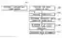
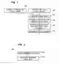
FIG. 1 describes a process flowchart according to the present invention.
In step 100, the digital output of the DUT clock is captured on an automated test equipment (ATE) digital channel.
In step 102, the (non return to zero) NRZ output data of the DUT is captured while the clock signal is captured on adjacent ATE channels.
Steps 100 and 102 occur concurrently.
In step 104, the digital clock data is analyzed. In step 104a, the data stream is multiplied by a DSP window, e.g. Hanning or Hamming. In step 104b, a fast Fourier transform (FFT) may be done on the windowed clock data and the resulting spectrum is analyzed. Alternatively, a discrete Fourier transform may be applied to the windowed clock data.
In step 106, the frequency and phase of the clock is calculated from the FFT spectrum.
In step 108, the number of device cycles captured is determined from the clock frequency.
In step 110, the alignment of the captured data to the correct number of device cycles is determined from the phase of the clock.
Although the present invention has been described in detail with reference to particular embodiments, persons possessing ordinary skill in the art to which this invention pertains will appreciate that various modifications and enhancements may be made without departing from the spirit and scope of the claims that follow.
Claims
I claim:1. A method for asynchronous digital capture comprising:
concurrently capturing the digital output of the device under test (DUT) clock on an automated test equipment (ATE) digital channel and capturing the NRZ output data of the DUT while the clock signal is captured on adjacent ATE channels;
analyzing the digital clock data such that a frequency spectrum is generated;
determining the frequency and phase of the clock is calculated from the spectrum;
determining the number of device cycles captured is determined from the clock frequency; and
determining the alignment of the captured data to the correct number of device cycles from the phase of the clock.
2. A method, as defined in claim 1, the step of analyzing including:
multiplying the digital clock data by a digital signal processing (DSP) window; and
performing a fast Fourier transform on the multiplied data.
3. A method, as defined in claim 2, wherein the digital signal processing window is selected from a group that includes Hanning and Hamming windows.
4. A method, as defined in claim 1, the step of analyzing including:
multiplying the digital clock data by a digital signal processing (DSP) window; and
performing a discrete Fourier transform on the multiplied data.
5. A method, as defined in claim 4, wherein the digital signal processing window is selected from a group that includes Hanning and Hamming windows.
Images & Drawings included:
Sources:
- United States Patent and Trademark Office - verify current appl. status at the USPTO↗
Similar patent applications:
Recent applications in this class:
- » 20230147947 2023-05-11
Systems and Methods for Measurement of a Parameter of a DUT - » 20220326304 2022-10-13
Setup time and hold time detection system and detection method - » 20190113571 2019-04-18
Determining the integrity of a computing device - » 20180328990 2018-11-15
Method and system for measuring a propagation delay and transmittance of a device under test (DUT) - » 20180106864 2018-04-19
Method and apparatus for high frequency analog-to-digital conversion - » 20180045779 2018-02-15
Feedback control circuit and power management module shortening feedback response time - » 20180017621 2018-01-18
Measuring a slew rate on-chip - » 20150015274 2015-01-15
Direct memory based ring oscillator (DMRO) for on-chip evaluation of SRAM cell delay and stability - » 20140091812 2014-04-03
Method of integrated circuit scan clock domain allocation and machine readable media thereof - » 20130214796 2013-08-22
DETERIORATION DETECTION CIRCUIT, SEMICONDUCTOR INTEGRATED DEVICE, AND DETERIORATION DETECTION METHOD
Recent applications for this Assignee:
- » 20170220706 2017-08-03
SYSTEMS, METHODS AND APPARATUS THAT EMPLOY STATISTICAL ANALYSIS OF STRUCTURAL TEST INFORMATION TO IDENTIFY YIELD LOSS MECHANISMS - » 20140189430 2014-07-03
System, methods and apparatus using virtual appliances in a semiconductor test environment - » 20110276302 2011-11-10
Re-configurable test circuit, method for operating an automated test equipment, apparatus, method and computer program for setting up an automated test equipment - » 20110238345 2011-09-29
System, method and computer program for detecting an electrostatic discharge event - » 20110231464 2011-09-22
State machine and generator for generating a description of a state machine feedback function - » 20110197086 2011-08-11
Data processing unit and a method of processing data - » 20110187399 2011-08-04
Signal distribution structure and method for distributing a signal - » 20110145654 2011-06-16
Method and apparatus for the determination of a repetitive bit value pattern - » 20110145645 2011-06-16
Test system and method for testing electronic devices using a pipelined testing architecture - » 20110140737 2011-06-16
Apparatus and method for estimating data relating to a time difference and apparatus and method for calibrating a delay line