Mounting apparatus for storage device
US20070194197A1
2007-08-23
11/560,844
2006-11-17
✅ Patent granted
US 8,074,942 B2
2011-12-13
-
-
Terrell McKinnon | Steven Marsh
2030-08-28
Abstract:
A mounting apparatus includes a bracket for receiving a storage device, and a latching member. The bracket includes a sidewall, and a top wall perpendicular to the sidewall. The latching member includes a main body pivotably fixed to the sidewall of the bracket, and a latching portion retainable on the top wall of the bracket. The main body forms two pins to extend through the bracket for fixing the storage device.
Inventors:
- Bin Huang 27 🇨🇳 Shenzhen, China
- CHUN-CHI LIANG 37 🇹🇼 Tu-Cheng, Taiwan
- CHUN-CHI LIANG 15 🇹🇼 Taipei Hsien, Taiwan
- DING-FANG LI 5 🇨🇳 Shenzhen, China
Assignee:
- HON HAI PRECISION INDUSTRY CO., LTD. 12,833 🇹🇼 Tu-Cheng, Taiwan
- HON HAI PRECISION INDUSTRY CO., LTD. 2,724 🇹🇼 Tu-Cheng, New Taipei, Taiwan
Interested in similar patents?
Get notified when new applications in this technology area are published.
Classification:
G06F1/187 » CPC main
Details not covered by groups - and; Constructional details or arrangements; Packaging or power distribution; Internal mounting support structures, e.g. for printed circuit boards, internal connecting means Mounting of fixed and removable disk drives
G11B33/12 » CPC further
Constructional parts, details or accessories not provided for in the other groups of this subclass Disposition of constructional parts in the apparatus, e.g. of power supply, of modules
A47F5/00 IPC
Show stands, hangers, or shelves characterised by their constructional features
H05K7/00 IPC
Constructional details common to different types of electric apparatus
H05K7/00 IPC
Constructional details common to different types of electric apparatus
Description
BACKGROUND OF THE INVENTION
1. Field of the Invention
The present invention relates to mounting apparatuses, and more particularly to a mounting apparatus for a storage device.
2. Description of Related Art
An electronic apparatus, such as a typical desktop computer, a tower computer, a server, and the like, usually includes storage devices, such as hard disk drives, compact disk read-only memory (CD-ROM) drives, digital video disc (DVD) drives, floppy disk drives, and the like. These devices are typically added to increase the functionality of the electronic apparatus as desired by a user. However, the installation of such devices in the electronic apparatus is always labor-intensive.
The installation of a hard disk drive in a computer typically involves the use of screws to attach the hard disk drive to a bracket of a computer chassis. However, these screws are usually too small and difficult to handle. Additionally, because of their small size, the screws are easily dropped, by an assembler, into the computer.
To address the aforementioned problems, a plurality of mounting apparatuses is invented to reduce the number of needed screws. For example, a pair of detachable rails is attached to opposite sides of a storage device with screws. The storage device is then slid into and secured to a drive bracket. However, the screws have to be removed to detach the rails from the storage device before replacing the storage device.
What is needed, therefore, is a mounting apparatus which facilitates convenient and secure mounting of a storage device in a bracket.
SUMMARY OF THE INVENTION
An exemplary mounting apparatus includes a bracket for receiving a storage device, and a latching member. The bracket includes a sidewall, and a top wall perpendicular to the sidewall. The latching member includes a main body pivotably fixed to the sidewall of the bracket, and a latching portion retainable on the top wall of the bracket. The main body forms two pins to extend through the bracket for fixing the storage device.
Other advantages and novel features will become more apparent from the following detailed description of preferred embodiment when taken in conjunction with the accompanying drawings, in which:
BRIEF DESCRIPTION OF THE DRAWINGS
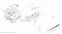
FIG. 1 is an exploded, isometric view of a mounting apparatus with a storage device in accordance with a preferred embodiment of the present invention, the mounting apparatus including a bracket, and a latching member;
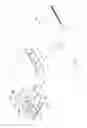
FIG. 2 is an enlarged isometric view of the latching member of FIG. 1, but viewed from another aspect;
FIG. 3 is an enlarged isometric view of the bracket of FIG. 1, but viewed from another aspect; and
FIG. 4 is an assembled view of FIG. 1.
DETAILED DESCRIPTION OF THE INVENTION
Referring to FIG. 1, a mounting apparatus for a storage device is provided in accordance with a preferred embodiment of the present invention. The mounting apparatus includes a bracket 30 for receiving a storage device 20, and a latching member 40 for fixing the storage device 20 to the bracket 30. The storage device 20 defines a pair of fixing holes 22 in a lateral side thereof.
Referring also to FIG. 3, the bracket 30 includes a first sidewall 31, a second sidewall 33, and a top wall 34 connecting with the first and second sidewalls 31, 33. Two openings are defined in two ends of the bracket 30 respectively. One of the openings acts as an entrance for the storage device 20 entering the bracket 30, and two opposite stop plates 36 are formed on ends of the first sidewall 31 and the second sidewall 33 respectively adjoining the other one of the openings. A pair of through holes 336 are defined in the second sidewall 33, corresponding to the fixing holes 22 of the storage device. Two spaced tabs 338 are punched outward from the second sidewall 33 substantially between the through holes 336. Two spaced fixing portions 332 protrude perpendicularly outward from the second sidewall 33 below the through holes 336, and each fixing portion 332 defines a pivot hole 334 therein. An aperture 344 (see FIG. 1) is defined in the top wall 34 adjacent the through holes 336 of the second sidewall 33.
Referring also to FIG. 2, the latching member 40 includes a main body 42, and a latching portion 44 extending perpendicularly inward from one end of the main body 42. Two pivot portions 422 extend perpendicularly outward from two lateral surfaces of the main body 42 adjacent the other end thereof, and a pivot 424 protrudes outward from each pivot portion 422. Two slots 426 are defined in the main body 42 corresponding to the tabs 338 of the second sidewall 33 of the bracket 30. Two pins 428 extend perpendicularly inward from the main body 42 corresponding to the through holes 336 of the second sidewall 33. Two dome-shaped protrusions acting as blocks 442 are formed on an inside surface of the latching portion 44. An operating portion 446 is bent outward from the latching portion 44.
Referring further to FIG. 4, in assembly, the pivot portions 422 of the latching member 40 are positioned between the fixing portions 332 of the second sidewall 33 of the bracket 30, and the pivots 424 of the pivot portions 422 engage in the pivot holes 334 of the fixing portions 332 respectively. The latching member 40 is thus pivotably fixed to the bracket 30 and is pivotable relative to the bracket 30 between an unlocked position and a locked position.
In use, the latching member 40 is pivoted to the unlocked position, the storage device 20 is installed into the bracket 30 from the entrance thereof. When an end of the storage device 20 abuts against the stop plates 36 of the bracket 30, the fixing holes 22 of the storage device 20 align with the through holes 336 of the second sidewall 33 of the bracket 30 respectively. The latching member 40 is rotated toward the bracket 30, the tabs 338 of the second sidewall 33 of the bracket 30 engage in the slots 426 of the latching member 40 respectively, and the pins 428 of the latching member 40 are extended through the through holes 336 of the second sidewall 33 and engage in the fixing holes 22 of the storage device 20 respectively. The blocks 442 of the latching portion 44 of the latching member 40 engage in the aperture 344 of the top wall 34 of the bracket 30, for retaining the latching member 40 on the bracket 30. The storage device 20 is thus fixed to the bracket 30 at the locked position.
To detach the storage device 20 from the bracket 30, the operating portion 446 of the latching member 40 is pulled up, and the blocks 442 of the latching member 40 are disengaged from the aperture 344 of the top wall 34 of the bracket 30. The latching member 40 is rotated relative to the bracket 30 to the unlocked position. The pins 428 of the latching member 40 are disengaged from the fixing holes 22 of the storage device 20 and withdrawn from the through holes 336 of the bracket 30. The tabs 338 of the second sidewall 33 of the bracket 30 are disengaged from the slots 426 of the latching member 40. The storage device 20 is ready to be detached from the bracket 30.
It is believed that the present embodiment and its advantages will be understood from the foregoing description, and it will be apparent that various changes may be made thereto without departing from the spirit and scope of the invention or sacrificing all of its material advantages, the example hereinbefore described merely being preferred or exemplary embodiment of the invention.
Claims
What is claimed is:1. A mounting apparatus for a storage device, the mounting apparatus comprising:
a bracket for receiving the storage device, the bracket comprising a first sidewall, a second sidewall, and a third wall connecting with the first sidewall and the second sidewall, the first sidewall defining two through holes therein; and
a latching member installable to the bracket, the latching member comprising a main body and a latching portion integral with the main body, the main body forming two pins to extend through the through holes of the bracket respectively for fixing the storage device, the latching portion configured to engage with a component of the mounting apparatus other than the first sidewall of the bracket for retaining the latching member on the bracket.
2. The mounting apparatus as claimed in claim 1, wherein the component is the third wall, the third wall has an aperture defined therein, the latching portion extends perpendicularly from an end of the main body, and a block is formed on the latching portion for engaging in the aperture.
3. The mounting apparatus as claimed in claim 2, wherein two spaced fixing portions protrude outward from the first sidewall of the bracket, each of the fixing portions defines a pivot hole, two pivot portions extend perpendicularly from the main body adjacent another end thereof, and each of the pivot portions forms a pivot for engaging in the corresponding pivot hole.
4. The mounting apparatus as claimed in claim 1, wherein two slots are defined in the main body of the latching member, and two spaced tabs extend outwardly from the first sidewall of the bracket for engaging in the corresponding slots.
5. The mounting apparatus as claimed in claim 1, wherein an operating portion is bent outward from the latching portion of the latching member.
6. The mounting apparatus as claimed in claim 1, wherein two openings are defined in two ends of the bracket respectively, and two opposite stop plates are formed on the bracket adjoining one of the openings, for abutting against the storage device.
7. A mounting apparatus for a storage device, the mounting apparatus comprising:
a bracket for receiving the storage device, the bracket comprising a sidewall and a top wall perpendicular to the sidewall; and
a latching member comprising a main body pivotably fixed to the sidewall of the bracket, and a latching portion configured to be retainable on the top wall of the bracket, the main body forming a pin to extend through the bracket for fixing the storage device.
8. The mounting apparatus as claimed in claim 7, wherein the top wall has an aperture defined therein, the latching portion extends from an end of the main body, and a block is formed on the latching portion for engaging in the aperture.
9. The mounting apparatus as claimed in claim 8, wherein two spaced fixing portions protrude outwardly from the sidewall of the bracket, and each of the fixing portions defines a pivot hole, two pivot portions extend perpendicularly from the main body adjacent the other end thereof, and each of the pivot portions forms a pivot for engaging in the pivot hole of a corresponding fixing portion.
10. The mounting apparatus as claimed in claim 7, wherein the sidewall of the bracket defines a through hole in a manner so as to allow the pin of the latching member to engage therein.
11. The mounting apparatus as claimed in claim 7, wherein a slot is defined in the main body of the latching member, and a tab extends outwardly from the sidewall of the bracket for engaging in the slot.
12. The mounting apparatus as claimed in claim 7, wherein two openings are defined in two ends of the bracket respectively, and a stop plate is formed on the bracket adjoining one of the openings, for abutting against the storage device.
13. A mounting apparatus mounting therein a storage device which defining at least one fixing hole at one sidewall thereof, comprising:
a mounting bracket configured to accommodate the storage device therein, the bracket comprising a first wall facing the sidewall of the storage device and a second wall perpendicular to the first wall, the first wall defining at least one through hole and the second wall defining an aperture;
a latching member pivotably mounted to the bracket, the latching member comprising a main body having at least one locking pin extending through the at least one through hole to engage in the at least one fixing hole, and a latching portion having a retaining part detachably engaging with the bracket in the aperture to retain the latching member to the bracket.
14. The mounting apparatus as claimed in claim 13, wherein the main body is pivotably mounted to the first wall via a pair of pivots pivotably received in a pair of pivot holes.
15. The mounting apparatus as claimed in claim 14, wherein the main body defines a slot between the pivots, and the first wall comprises a tab stamped outwardly therefrom for extending through the slot.
16. The mounting apparatus as claimed in claim 13, wherein the latching member has a substantially L shape and the latching portion extends perpendicularly from the main body.
17. The mounting apparatus as claimed in claim 13, wherein the latching member is unitary.
18. The mounting apparatus as claimed in claim 17, wherein a free end of the latching portion opposing the main body is folded to form an operating portion.
19. The mounting apparatus as claimed in claim 17, wherein the mounting bracket comprises a pair of opposite opening ends, one of the opening ends acting as an entrance for the storage device entering into the bracket, the mounting bracket further comprising a pair of stop plates extending into the other one of the opening ends for abutting against the storage device.
20. The mounting apparatus as claimed in claim 13, wherein the retaining part comprises a dome-shaped protrusion stamped from the latching portion toward the second wall.
Images & Drawings included:


Sources:
- United States Patent and Trademark Office - verify current appl. status at the USPTO↗
Similar patent applications:
- » 20170125065
Storage device carrier and mounting apparatus for storage device - » 20110266405
Storage device mounting apparatus - » 20150153790
Data-storage device mounting apparatus - » 20130050925
Data storage device mounting apparatus - » 20050280983
Storage device mounting apparatus - » 20160161997
Supporting device and mounting apparatus for data storage device and electronic device having the same - » 20050195564
Mounting apparatus for storage device - » 10702837
Mounting apparatus for storage devices - » 10857694
Mounting apparatus for storage devices - » 20050121581
Mounting apparatus for storage devices
Recent applications in this class:
- » 20250181123 2025-06-05
COMPUTER CHASSIS - » 20250138604 2025-05-01
HOT SWAPPABLE DRIVE CAGE - » 20250021142 2025-01-16
FIXING BRACKET FOR FACILITATING ASSEMBLY AND DISASSEMBLY OF HARD DISK IN ELECTRONIC DEVICES - » 20250021141 2025-01-16
Mounting System for Storage Drive - » 20240411349 2024-12-12
MOUNT BRACKET, STORAGE DEVICE ASSEMBLY, AND SERVER - » 20240302877 2024-09-12
QUICK RELEASE MECHANISM AND ELECTRONIC ASSEMBLY - » 20240295908 2024-09-05
Transverse drive tray assembly - » 20240288915 2024-08-29
DRIVE ADAPTOR FOR A DRIVE CARRIER - » 20240264645 2024-08-08
INTEGRATED LOCKING MECHANISM FOR DRIVE BLANKS - » 20240256010 2024-08-01
FIXING FRAME FOR COMPUTER APPARATUS
Recent applications for this Assignee:
- » 20140233961 2014-08-21
Optical communication module including optical-electrical signal converters and optical signal generators - » 20140083669 2014-03-27
HEAT SINK - » 20140063746 2014-03-06
Electronic device with heat dissipation assembly - » 20140061224 2014-03-06
AUTOMATIC VENDING MACHINE - » 20140060914 2014-03-06
Enclosure with shield apparatus - » 20140058727 2014-02-27
MULTIMEDIA RECORDING SYSTEM AND METHOD - » 20140055955 2014-02-27
Fastener - » 20140055322 2014-02-27
DISPLAY SYSTEM AND HEAD-MOUNTED DISPLAY APPARATUS - » 20140054439 2014-02-27
CONTAINER DATA CENTER WITH SUPPORTING APPARATUS - » 20140054311 2014-02-27
AUTOMATIC VENDING MACHINE WITH MOVING MEMBER FOR PRODUCTS