Microfibrous Composition Comprising Siliceous Spicules Of Spongiaria, Processes And Equipment For Obtaining Them
US20070200083A1
2007-08-30
10/572,520
2004-09-17
Abstract:
A microfibrous composition is described, particularly used for heat and sound insulation, which comprises an amount of siliceous spicules of spongiaria ranging from 70% to 99% by weight, based on the total weight of the composition. Further, the process and equipment designed to obtain said microfibrous composition are described.
Interested in similar patents?
Get notified when new applications in this technology area are published.
Classification:
C03C13/00 » CPC main
Fibre or filament compositions
B82Y30/00 » CPC further
Nanotechnology for materials or surface science, e.g. nanocomposites
C04B35/14 » CPC further
Shaped ceramic products characterised by their composition ; Ceramics compositions ; Processing powders of inorganic compounds preparatory to the manufacturing of ceramic products based on oxide ceramics based on silica
C04B35/18 » CPC further
Shaped ceramic products characterised by their composition ; Ceramics compositions ; Processing powders of inorganic compounds preparatory to the manufacturing of ceramic products based on oxide ceramics based on silicates other than clay rich in aluminium oxide
C04B35/6303 » CPC further
Shaped ceramic products characterised by their composition ; Ceramics compositions ; Processing powders of inorganic compounds preparatory to the manufacturing of ceramic products; Forming processes; Processing powders of inorganic compounds preparatory to the manufacturing of ceramic products; Preparing or treating the powders individually or as batches ; preparing or treating macroscopic reinforcing agents for ceramic products, e.g. fibres; mechanical aspects section using additives specially adapted for forming the products, e.g.. binder binders Inorganic additives
C04B35/80 » CPC further
Shaped ceramic products characterised by their composition ; Ceramics compositions ; Processing powders of inorganic compounds preparatory to the manufacturing of ceramic products; Ceramic products containing macroscopic reinforcing agents containing non-metallic materials Fibres, filaments, whiskers, platelets, or the like
F27D1/0006 » CPC further
Casings; Linings; Walls; Roofs; Linings or walls Linings or walls formed from bricks or layers with a particular composition or specific characteristics
F27D1/0009 » CPC further
Casings; Linings; Walls; Roofs; Linings or walls; Linings or walls formed from bricks or layers with a particular composition or specific characteristics Comprising ceramic fibre elements
C04B2235/3418 » CPC further
Aspects relating to ceramic starting mixtures or sintered ceramic products; Composition of constituents of the starting material or of secondary phases of the final product; Constituents and secondary phases not being of a fibrous nature; Non-metal oxides, non-metal mixed oxides, or salts thereof that form the non-metal oxides upon heating, e.g. carbonates, nitrates, (oxy)hydroxides, chlorides Silicon oxide, silicic acids, or oxide forming salts thereof, e.g. silica sol, fused silica, silica fume, cristobalite, quartz or flint
C04B2235/349 » CPC further
Aspects relating to ceramic starting mixtures or sintered ceramic products; Composition of constituents of the starting material or of secondary phases of the final product; Constituents and secondary phases not being of a fibrous nature; Non-metal oxides, non-metal mixed oxides, or salts thereof that form the non-metal oxides upon heating, e.g. carbonates, nitrates, (oxy)hydroxides, chlorides Clays, e.g. bentonites, smectites such as montmorillonite, vermiculites or kaolines, e.g. illite, talc or sepiolite
C04B2235/526 » CPC further
Aspects relating to ceramic starting mixtures or sintered ceramic products; Composition of constituents of the starting material or of secondary phases of the final product; Constituents or additives of the starting mixture chosen for their shape or used because of their shape or their physical appearance; Constituents or additives characterised by their shapes; Fibers characterised by the length of the fibers
C04B2235/5264 » CPC further
Aspects relating to ceramic starting mixtures or sintered ceramic products; Composition of constituents of the starting material or of secondary phases of the final product; Constituents or additives of the starting mixture chosen for their shape or used because of their shape or their physical appearance; Constituents or additives characterised by their shapes; Fibers characterised by the diameter of the fibers
C04B2235/5276 » CPC further
Aspects relating to ceramic starting mixtures or sintered ceramic products; Composition of constituents of the starting material or of secondary phases of the final product; Constituents or additives of the starting mixture chosen for their shape or used because of their shape or their physical appearance; Constituents or additives characterised by their shapes Whiskers, spindles, needles or pins
C04B2235/5284 » CPC further
Aspects relating to ceramic starting mixtures or sintered ceramic products; Composition of constituents of the starting material or of secondary phases of the final product; Constituents or additives of the starting mixture chosen for their shape or used because of their shape or their physical appearance; Constituents or additives characterised by their shapes Hollow fibers, e.g. nanotubes
C04B2235/5296 » CPC further
Aspects relating to ceramic starting mixtures or sintered ceramic products; Composition of constituents of the starting material or of secondary phases of the final product; Constituents or additives of the starting mixture chosen for their shape or used because of their shape or their physical appearance; Constituents or additives characterised by their shapes with a defined aspect ratio, e.g. indicating sphericity
E04B1/74 IPC
Constructions in general; Structures which are not restricted either to walls, e.g. partitions, or floors or ceilings or roofs; Insulation or other protection; Elements or use of specified material therefor Heat, sound or noise insulation, absorption, or reflection . Other building methods affording favourable thermal or acoustical conditions, e.g. accumulating of heat within walls
Description
This application claims priority of Brazilian patent application No. P10304176-0, the disclosure thereof being hereby incorporated by reference.
The present invention relates to a composition of microfibrous texture essentially comprising siliceous spicules of spongiaria, as well as processes and equipment for obtaining them. Said microfibrous composition may be used, among other uses, for thermal insulation. The techniques involved in the making of it are related to the ceramic industrial sector and the sector of manufacturing artifacts for civil architecture.
Description of the Prior Art
Bodies composed by fibers, for example from animal hair, are mostly good thermal insulators. So, various products constituted by natural fibers are utilized. In the animal kingdom there are sheep wool, furs from rabbit and other animals. In the vegetable kingdom, there are wooden fibers, from which paper and cardboard are made, and other, such as cotton fibers to make various fabrics. In the mineral kingdom, there are products such as chrysotile, ordinarily called amianthus.
Various fibrous synthetic products have arisen and are good products for heat and sound insulation. Among them, polymeric fibers such as nylon and polyesters stand out. In a field of use for insulation designed for higher temperatures, glass fibers, “rock wools”, calcium silicate fibers and also the so-called “ceramic fibers” have appeared.
In addition to the fibrous form, there are also insulants having high porosity, such as corks of vegetable origin, expanded polystyrene and polyurethane, besides kaolin-based and/or diatomite-based insulants.
Focusing now on the filed of high-temperature fibrous insulators, it can be noticed that amianthus is a very interesting product, but there is today serious restrictions to the use thereof, mainly due to questions of salubriousness. Since this product is expected to go out of the market, only the above-mentioned synthetic fibers will be left.
The glass fibers are relatively noble products and may be long, continuous or short filaments, of great chemical and physical homogeneity. They resist up to 800° C. and are commercialized in webs, being relatively expensive.
The calcium silicate fibers are less expensive fibers, but are intended to be used at temperature no higher than 600° C. They are also sold in webs or as semi-rigid aggregate products.
The “rock wools” are products derived from the basaltic rock melting. They sand temperatures around 800° C. and are cheaper than glass fibers. They are commercialized in webs or in semi-rigid pieces. Such products today are often used in domestic and industrial ovens such as bakeries and also in insulation of solar heater.
The “ceramic fibers” are more refractive having types which stand temperatures from 1.250° C. to 1.400° C., being some of them able to stand even higher temperatures. They have, generally, silico-aluminous to aluminous composition, and their refractoriness increases according to the amount of aluminum comprised therein. There is also the pure silica fiber with good refractory properties. The costs of the manufacturing theses fibers depend on their deterioration resistance under high temperatures. Generally, all types of this fiber have good thermal insulation properties. However, theses fibers, under high temperatures, deteriorate by melting or get fragile by recristalization mainly of christobalite in the glass mass. The ceramic fibers are commercialized in long fibers constituting webs, or then, in short fibers, generally, aggregated by resin binding components constituting semi-rigid products.
Ceramic fibers exhibit, as a restriction to its use, low compression strength or bending strength, even in the so-called “rigid” products, and a high linear retraction of up to 8%, found in the first burning at temperatures of continuous use. In addition, such products are quite expensive with respect to other high-temperature insulators.
The microfibrous composition of the present invention comprises siliceous spicules of spongiaria (explained in greater detail later) and often look like synthetic products constituted by short ceramic fibers.
Siliceous spicules of spongiaria are cylindrical microneedles with length on the order of 500 μm, thickness on the order of 10 μm, essentially composed of silica. Such spicules can be qualified as fibers or microfibers due to said dimensions. Such terminology will be used hereinafter, in this context.
Said siliceous spicules of spongiaria are parts remaining from skeletons of colonies of certain organisms that are scientifically called sponges. Sponges are minute animals of aquatic life, which form colonies called spongiaria. Cyclically, the colonies die, releasing the spicules that are dispersed in the aquatic medium, settling on the beds of lakes or sea, and are then fossilized. This process, which occurs after tens or hundreds of years in the same biological medium, enables the formation of expressive deposits of these materials.
Important concentrations of spicules of sponges are found in sedimentary extracts of specific geological environments, always mixed with clays, sands and other materials predominantly of aquatic organic origin. Rocks rich in these materials receive the geological name “spongilites”, being ordinarily known, in Brazil, as “barro de pó de mico” or simply “mico” which corresponds to their appearance similar to fine hairs.
Ceramic products derived from materials constituted by siliceous spicules of spongiaria are widely known. By way of clarification, the following is reported:
-
- a) since before Brazil was discovered, certain indigenous tribes had already used materials derived from sponges in ceramic craftwork for making highly resistant pots intended for cooking food;
- b) in Brazil a pottery industry exists since centuries ago, which is based specifically on these materials. At present, it is estimated that in this country about 50,000 families make a living in this activity, scattered in small communities, some of them with over 5,000 inhabitants, always located near of around natural deposits;
- c) the ceramic pieces, made from these materials, being preferably bricks, are characterized by their high strength, their heat-insulation properties and some refractoriness; by virtue of these properties, they are used in civil architecture, in making ceramic furnaces, barbecues and charcoal-industry furnaces, among other possibilities. They are ordinarily known as “tijolos de mico” or “tijolos de pó de mico”;
- d) the formulations used, for example, for making ceramic pieces are most varied, depending upon the availability of ores at the place or at the moment. So, according to the place or time, the production of pieces varies much from pieces very rich in microfibers with up to about 50% (by weight) to pieces very poor in microfibers with from 5% to 10%. Clays and sands, which occur close to the microfibers in ores, constitute the rest of the formulations, with few exceptions. These natural concentrations of microfibers of spongiaria are not sufficient for providing pieces with excellent heat and sound insulation properties.
Microfibers are considered the strong point of these materials. So, products having the useful properties, optimized from microfibers were developed, thus obtaining levels of industrial conformity that meet the present-day specific requirements. In order to achieve the results known today, the following steps were necessary:
-
- a—development of technology for beneficiation of ores leading to the separation of microfibers;
- b—multiple assays on formulations and development and optimization thereof;
- c—systematic studies involving the shaping of pieces and technical characterization of the microfibrous compositions obtained on laboratory scale; and
- d—development of technology for shaping and manufacturing artifacts on an industrial-production scale.
With the study of these materials over these years, it has been possible to obtain much purer concentrates thereof, that is to say, exhibiting high concentrations of spicules. With these concentrates, high-quality insulating pieces with the help of industrial shaping techniques can be made, which are also the object of the present invention.
OBJECTIVES OF THE INVENTIONAn objective of the present invention is to provide a microfibrous composition comprising siliceous spicules of spongiaria, the amount thereof ranging from 70% to 99% by weight, based on the total weight of the composition. This amount is much higher than that already obtained in the prior art, and resulting in relevant improvements of the physico-chemical properties inherent in the pieces made with this composition.
Another objective of the present invention is to provide the processes and the respective equipment for obtaining the microfibrous composition aimed at.
BRIEF DESCRIPTION OF THE INVENTIONThe objectives of the present invention are achieved by means of a microfibrous composition, particularly used for heat insulation and sound insulation, characterized by comprising an amount of siliceous spicules of spongiaria ranging from 70% to 99% by weight, based on the total weight of the composition.
The objectives of the present invention are also achieved by means of a process for obtaining the microfibrous composition, which comprises the following steps:
-
- a—mixing the microfibers with water and at least one binding component in a friction tank;
- b—stirring said mixture until a homogeneous pulp is achieved;
- c—shaping the pulp in a shaping equipment to eliminate the excess of water and binding components and to obtain a residual cake;
- d—curing the residual cake by a curing process, so as to obtain the microfibrous composition.
Further, the objectives of the invention are achieved by means of an equipment to promote the shaping of the residual cake, which comprises:
-
- a mold associated, at its upper part, to a container and, at its lower part, to a bulkhead;
- said mold being further associated, at its lower part, to a liquid collector and to an outlet for the residual pulp.
The microfibrous composition presented now has many advantages over the products based on synthetic fibers and over the products that comprise a lower concentration of siliceous microfibers, above all in heat insulation, strength and dimensional stability when used at high temperatures, some of which are listed below.
While some of the fibers of the prior art, such as glass fibers, “rock wools”, calcium silicate fibers, among others, are resistant to temperatures of up to 800° C., the microfibrous compositions of this invention exhibit heat strength at higher temperatures, reaching temperatures of about 1,250° C.
It is possible to make larger and less dense pieces with the microfibrous composition of the present invention, in comparison with the pieces made from insulators of the kaolin/diatomite lines.
In comparison with ceramic-fiber compositions:
-
- the microfibrous composition of the present invention exhibits dimensional stability, configured by linear retraction in the re-burning on the order of 1 mm/m, or 0.10%, whereas pieces made from ceramic fibers exhibit values even higher than 4.5%.
- The more rigid pieces of ceramic fibers mostly deform under stress, unlike the pieces comprising the microfibrous composition of the present invention, which exhibit rigidity even to rupture.
- With regard to the strength, measuring pieces having a specific mass of 0.40 g/cm3, bodies composed of the microfibrous composition of the present invention exhibit values on the order of 0.47 and 0.41 MPa of compression strength and fending strength, respectively, while bodies composed of ceramic fibers exhibit compression strength on the order of 0.25 MPa and a virtually null value with regard to the bending strength.
- The pieces comprising the microfibrous composition of the present invention exhibit heat-insulation properties very similar to those inherent in the best ceramic-fiber pieces. For example, at a temperature of the hot face on the order of 1,000° C., pieces made from the microfibrous composition exhibit a heat conductivity coefficient of 0.192 W/m.K, whereas an optimum product constituted by ceramic fibers exhibit a heat conductivity coefficient of 0.190 W/m.K.
Comparing the microfibrous composition of the present invention with compositions made from rock wool and calcium silicate wool:
-
- the microfibrous composition exhibits higher values of refractoriness properties with respect to the pieces made from rock wool and calcium silicate wool.
- Further, it exhibits greater dimensional stability upon being subjected to high temperatures.
With regard to the insulating products composed by kaolin/diatomite:
-
- the pieces (bricks) made from kaolin/diatomite usually exhibit dimensions corresponding to 224×112×76 mm. On the other hand, by using the methods of making pieces explained in greater detail later, it is possible to make larger pieces comprising the microfibrous composition of the present invention, with at least one of the dimensions even larger than 1.0 meter each.
- It is possible to make pieces comprising the microfibrous composition of the present invention exhibiting apparent specific weight much lower in comparison with all the known pieces made with kaolin and diatomite.
The present invention will now be described in greater detail with reference to embodiments represented in the drawings. The figures show:
FIG. 1 illustrates a flow diagram of the industrial processing for obtaining the microfibrous composition of the present invention;
FIG. 2 illustrates a first schematized embodiment of the equipment used in the process of obtaining the microfibrous composition of the present invention;
FIG. 3 illustrates a second schematized embodiment of the equipment used in the process of obtaining the microfibrous composition of the present invention; and
FIG. 4 illustrates a third schematized embodiment of the equipment used in the process of obtaining the microfibrous composition of the present invention.
DETAILED DESCRIPTION OF THE INVENTIONThe microfibrous composition of the present invention is composed of microfibers of siliceous spicules of spongiaria and binding components such as various kinds of clay. It is intended for uses the require refractoriness properties at high temperatures of up to 1,250° C. or higher.
1—Microfibers of Spongiaria
The microfibers must be cleaned, loosened and sorted according to their size in order to be used in the microfibrous composition of the present invention.
In order to obtain microfibers free from natural impurities industrially, ores are processed. The processes comprise hydration and attrition by using chemical dispersants, thus obtaining a pulp in which grains are sorted later. Sand and fine residues are removed by hydrocycloning and settling, respectively.
The microfibers may have varied shapes, that is, they may be constituted by entire or fragmented original spicules, either mixed or not, as long as they exhibit the properties and characteristics listed below.
| Specific weight | 2.0 to 2.2 g/cm3 |
| Maximum length | About 500 μm |
| Average length | About 200 μm |
| Average thickness | About 10 μm |
| Length/thickness ratio | 10 to 20 |
| Appearance | Rectilinear, transparent, rigid micro- |
| needles | |
| Mineralogical composition | Amorphous silica, and it may exhibit |
| christobalite traces | |
| Morphologic composition | Acicular (needles) with hollow core, |
| cylindrical, very smooth, with both | |
| endings tapered when entire | |
| Chemical composition | Essentially SiO2 (more than 98% after |
| calcination) and impurities with | |
| Al2O3 from clay contaminants | |
| Loss in fire | 6 to 9% of volatile components |
| (water and carbon dioxide) | |
| Pyrometric cone | 1740 to 1760° C. |
According to the properties and characteristics described above, the spicules of spongiaria are needles or acicules, the maximum length of which is of 0.5 millimeters, being transparent, rigid, composed of amorphous silica and volatile components. A ratio between length and thickness on the order of from 10 to 20 times and length smaller than 0.5 mm enable them to be technically called fibers or microfibers.
2—Microfibrous Composition
As shown before, the microfibrous composition has a microfibrous texture and is essentially constituted by siliceous spicules of spongiaria. It has mainly the characteristics described below:
| Range of apparent specific mass | From 0.06 to 1.20 g/cm3 |
| Average apparent specific mass | 0.50 g/cm3 |
| Range of porosity | 45 to 95% |
| Average porosity | 70% |
| Maximum pyrometric cone | 1740° C. |
| Mineralogical composition | Microfibers: more than 70%, binding |
| components: less than 30% | |
| Chemical composition | SiO2 (after calcinations): more than |
| 80% Al2O3 + Na2O + FeO + others: | |
| less than 20% | |
| Loss in fire | 0 to 10% |
Note: |
|
The mechanical properties of the microfibrous composition depend upon the binding component chosen to be used in its composition. |
The function of the binding component is to provide adhesion of the microfibers. The main binding components that may be used in the present composition are: aluminous clays, kaolinitic clays, smectitic clays, mixed clays, colloidal silica and silicic acids. However, other binding components may be used since they exhibit the characteristics necessary for the formulation of the microfibrous composition already described.
Tests carried out have shown a relative success with: aluminous clays, kaolinitic clays, smectitic clays, mixed clays or mixture thereof and colloidal silica, among others. The choice thereof will be conditioned to the final destination of the microfibrous composition. In the field of heat insulators for high temperatures, for example, kaolinitic clays or aluminous clays may be used and, for low temperatures, smectictic clays.
The process of curing said microfibrous composition also varies, depending upon the binding component chosen. This process may be carried out: in open air, in ovens or in calcining furnages.
The apparent specific mass of the microfibrous composition is a function of the special arrangement of the microfibers, as well as of the distribution of average sizes thereof. Values on the order from 0.40 to 0.60 g/cm3 are more commonly obtained. For lower values, it is necessary to apply procedures that open the microfiber mesh, as for example, by introducing fillers with volatile components and, for higher values, procedures like the application of vibrations that cause approximation thereof, making the aggregate dense. Values from 0.06 to 1.2 g/cm3 have already been obtained in this way.
The porosity is inversely proportional to the apparent specific mass, in this case, with very high values, ranging from 45% to 95%.
The melting temperature of the microfibrous composition will depend upon the type of binding component used. The microfibers, being of essentially siliceous nature, have a melting point close to the melting point of quartz, on the order of from 1740 to 1760° C. Bound by colloidal silica, for instance, the microfibrous composition exhibits melting strength close to this value. Bound by kaolinitic clays, for instance, the melting point will be on the order of from 1550 to 1600° C. Aluminous clays permit higher melting temperatures, on the order of from 1600 to 1650° C. Bound by smectitic clays, there will be a reduction in the melting point to about 1350° C.
The mechanical properties of the microfibrous composition will also depend upon the type of binding component used. There are destinations for which there is no interest in high mechanical performance, as is the case of certain heat insulators for “back-up” furnaces, that is to say, those heat insulators that do not receive heat directly from the hottest portion of the furnace. On the other hand, there are cases in which strength is fundamental. Significant results may be achieved, for instance, in pieces whose binding components are kaolinitic clays sterilized at high temperatures, reaching a pressure of up to 1.0 MPa of bending for pieces with apparent specific mass of 0.50 g/cm3, which is a surprisingly value with respect to heat insulators available on the market. In the following table, some results are shown, which were achieved after calcinations at 1250° C., using various types of binding components.
| Bending | |||
| Type of binding | Apparent specific | Cold compression | strength |
| component | mass g/cm3 | strength (MPa) | (MPa) |
| Kaolinitic clay | 0.69 | 1.80 | 1.04 |
| Aluminous clay | 0.70 | 2.27 | 1.17 |
| Smectitic clay | 0.75 | 4.95 | 2.56 |
| Colloidal silica | 0.82 | 0.95 | 0.26 |
It can be noticed that the best binding component to be used in the constitution of the microfibrous composition is smectitic clay, when the wish is to obtain high values of strength.
In addition to the strength variation configured by the various types of binding components, there are naturally other variations that result from the final apparent specific masses of the microfibrous composition obtained. The table below illustrates the values of compression strength obtained after burning, at a temperature of 1,250° C., test bodies having kaolinitic clays as binding components:
| Apparent specific mass (g/cm3) | Cold compression strength (MPa) |
| 0.20 | 0.15 |
| 0.30 | 0.40 |
| 0.40 | 1.00 |
| 0.50 | 1.80 |
| 0.60 | 2.60 |
It can be concluded then that, when the microfibrous composition comprises kaolinitic clay as a binding component, the cold compression strength increases proportionally with the increase in the apparent specific mass.
The microfibrous composition generally comprises at least 70% of microfibers and the rest of binding components. In most products, the amount of microfibers is higher than 90%, reaching 99% of the composition, and the remaining amount is of binding components, which compose an extremely thin film enclosing the microfibers.
Regarding the chemical composition, the amount of silicon dioxide ranges from about 80% to about 99.0%, and this latter value may be obtained when siliceous chemical binding components are used, like colloidal silica.
2.1 Examples of Microfibrous Composition
The microfibrous composition is basically composed of microfibers and binding components, the microfibers being the main components, the amount of which ranges from 70 to 99%. Examples of microfibrous composition are described below (values in weight, dry base):
| Amount of microfibers | Type of binding component | |
| Example | (% by weight) | (% by weight) |
| 1 | 70 to 95% | 5 to 30% of kaolinitic clay |
| 2 | 70 to 95% | 5 to 30% of aluminous clay |
| 3 | 75 to 97% | 3 to 25% of smectitic clay |
| 4 | 70 to 95% | 5 to 30% of mixed clays |
| 5 | 82 to 99% | 1 to 18% of colloidal silica |
The most usual composition for the production of articles having excellent heat and sound insulation properties preferably contain about 90% by weight of microfibers. In case the binding component is colloidal silica, this amount then becomes 96%.
Some more interesting examples for industry may be pointed out, namely:
| Amount of | Amount of binding | ||
| Type of binding | microfibers | component | |
| Example | component | (% by weight) | 9% by weight) |
| 1 | Kaolinitic clay | 90 | 10 |
| 2 | Colloidal silica | 96 | 4 |
The above examples are preferred embodiments of the microfibrous composition of the present invention and should not be taken as limitations thereof. So, many variations of composition may be carried out within the protection scope delimited by the accompanying claims.
3—Processes for Obtaining the Microfibrous Composition
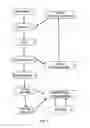
The process for obtaining the microfibrous composition is illustrated in FIG. 1 and comprises the following steps:
-
- a) a mixture of water and at least one binding components is prepared in the proportions of from 80% to 90% of water and the rest of binding components, obtaining the pulp called barbotine;
- b) an amount of previously cleaned and loosened microfibers 1 is added, together with the barbotine pulp at a ratio ranging from 1:3 to 1:5 in an attrition tank 2, provided with rotary tabs driven by reducing mechanisms, to be mixed and homogenized so as to yield a homogeneous pulp 4;
- c) the pulp 4 is routed through tubes to a shaping equipment 5, where the shape and the consistency of the microfiber agglomerate are checked; settling processes with or without vibrations, pressure or vacuum filtrations may be employed for this purpose, according to the type of equipment 5, as will be detailed later;
- d) in the shaping equipment 5, a wet residual cake 6 is formed with the arrangement of the fibers exhibiting a density on the order of 0.8 to 1.0 g/cm3, varying according to the degree of aeration to which the residual cake 6 is subjected, which enables the handling thereof on special trays; the mixture that comprises water and residual binding components 3 is eliminated or recovered for recirculation;
- e) the residual cake 6 obtained will undergo a curing process 7, which is preferably carried out by drying in ovens; the drying of the residual cake 6 obtained will render the products rigid, imparting strength to them, resulting in the microfibrous composition.
Optionally, the microfibrous composition obtained with the curing process 7 may then undergo a firing process 8 at temperatures of up to 800° C., carried out in ceramic furnaces. This process is suitable for the microfibrous composition the binding components of which are clays that should be sintered at high temperatures. This firing process 8 may be of the continuous type, with the use of tunnel furnaces or roller furnaces or else intermittent, using various types of furnaces, such as the traditional type, called “demijohn furnace”, or others.
Further, the cured microfibrous composition, depending upon the requirements of the field of utilization, may be mechanically rectified, whereby warps and imperfections beyond the standard dimension are eliminated. Such grinding 9 is carried out by using grinders.
4—Equipment for Obtaining the Microfibrous Composition
The processes, presented in summary, are three:
-
- a) settling including the variants “simple” or “with vibrations”;
- b) filtration under pressure, and
- c) Vacuum filtration.
The settling process consists of the physical actuation of this process on pulps held in containers, called molds, during an interval of time of about 20 minutes per operation, resulting in a relatively rigid body, configured by the entanglement of the microfibers. Vibrations may be applied in the course of the settling, promoting a decrease in empty spaces between the microfibers, generating a microfibrous composition of greater relative density. Such obtained piece, depending upon the binding component used and the proposed use, should be made rigid or cured by drying in the open air or ion ovens; such drying may or may not be followed by a firing at high temperatures. This process will be described in greater detail later.
On the other hand, the pressure-filtration process consists in obtaining a filtered cake, by forced passage of the pulps containing binding components and microfibers through a semipermeable partition, usually a thin web, which contains the microfibers and part of the binding components. Such a filtered cake is wet, consistent to the extent that it can be handled with shapes that are given by molds coupled to the semipermeable partition. The pressure is provided by the compressed air to be injected in bell jars overlapping the web, or else by forced pumping of the pulp itself. This process will be described in greater detail later.
Finally, the vacuum-filtration process is similar to that described before, with the difference that the filtration accelerating agent is vacuum, which is applies in a hermetic chamber positioned below the semipermeable partition. The cake obtained will also be subjected to drying and may also be fired at high temperatures, depending upon the choice of the binding component and upon the destination thereof.
All the residual pulps of the three processes defined before are re-used after being reconditioned, the consumed portions of binding component being replaced.
4.1 First Embodiment of Process and Equipment—Settling Process
The microfibrous composition may be obtained by means of a process called settling process, which consists in the actuation of this process on pulps containing microfibers, where water and the binding components are also mixed.
The shaping may be made by means of a simple settling process, wherein the particles settle according to the viscosity of the pulp at speeds ranging from 0.5 to 2.0 cm/min, resting on the bottom of the mold, on top of each other, forming a settled cake. On the other hand, in the case of settling under vibrations, unlike the simple settling, one applies vibrations of frequencies ranging from 0.02 Hz to 40 KHz, provided by mechanical, electric and also ultrasonic vibrators. Such vibrations, applied to the molds, will be transferred to the settled cake, compacting it and generating the product different from that obtained by simple settling.
At the end of the process, the overlaying pulp, now free from the microfibers, may be eliminated. In the case of molds containing fine webs at the lower part, the elimination of the pulp may take place by pouring through the cake obtained, by gravity or by forced pouring, by means of vacuum chambers and pressure chambers coupled to the mold. In case impermeable molds are opted, the residual pulp is removed by pumping or by outflow. The microfibers, which are settled on the bottom, intricate arrangements in a single, permeable cake, exhibiting density on the order from 0.8 to 1.0 g/cm3, varying according to the degree of aeration to which the residual cake is subjected, which enables the handling thereof on special trays.
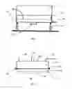
In FIG. 2, a schematic drawing of equipment designed for molding pieces by settling is illustrated, with or without application of vibrations, with removal of the residual pulp by pouring through the settled cake.
This equipment comprises a mold 10, where the mixture of the microfibrous composition is held, at its upper part, a container 11 is applied, intended to hold a large amount of pulp 4. At the lower part of the mold there is a partition 12, constituted by a very thin web, which provides a very slow outflow of permeable liquids in the settled material. Below the partition 12, there is a liquid collecting trough 13, which is welded to the mold 10; this trough 13 has a bore for letting out the residual pump 14 and, at its bottom, it may have a coupled vibrator 15. The whole equipment is supported by a spring device 16, which may be composed of helical springs or rubber pads of high strength, fixed to the bottom of the trough 13.
The mold 10 may be of any shape, as long as it will hold the volume of pulp that comprises the microfibers and the binging component(s). Particularly, the mold 10 is triangular in shape with dimensions on the order of 1.40 m×0.70 m. The container 11 may be of any shape that may be useful to the equipment, that is to say, it may represent a space corresponding to the pulp volume to be processed. The web 12 is preferably very thin, in order to provide better retention of liquid, including a product with less water, but the mesh aperture of the web may vary according to the final product to be obtained. Preferably, one uses a web made of stainless still in meshes of 60-200 mesh-tyler. The liquid collecting trough 13 has the function of collecting the liquid removed from the initial cake; so, its shape or size are not relevant.
In a molding operation, the pulp 4 containing known amounts of microfibers and binding components (obtained by the process schematized in FIG. 1) is placed in the mold 10. The pulp 4 remains setting for an interval of time ranging from 20 to 30 minutes, so as to achieve the total settling of the particles and the outpour of the residual liquids through the web 12, being collected by the trough 13 and eliminated by the outlet 14. At this moment, vibrations may be applied by actuating the vibrator 15, which will make the whole assembly vibrate, from the spring device 16, which is preferably composed of helical springs, whereby the settled cake is made dense.
For removal of the intermediate product formed here, use manual techniques or suitable mechanisms may be used. A manual technique indicated for removal of the intermediate product above consists in placing a preferably metallic or wooden tray on it, securing it to the side of the mold, turning the whole equipment and supporting the tray on an easel. Once this has been done, the tray is released and the equipment is raised, while the filtered piece remains, now released from the mold, on the easel. This technique may be carried out mechanically; for this purpose, all you need is a turning mechanism at the whole equipment via cranes and a mechanism for removing the tray by means of a platform intended to collecting the tray containing the piece thereon, which moves vertically by mechanical actuation. The choice of the best technique for removing the intermediate product depends upon the type and dimensions of the pieces to be made.
4.2 Second Variation of Process and Equipment—Process of Filtration Under Pressure
The process of filtration under pressure consists in applying pressure onto the pulps containing microfibers, forcing the passage thereof through a partition having small bores, generating a filtered, wet and consistent cake that may be handled (it exhibits a density on the order of 0.8 to 1.0 g/cm3, varying according to the degree of aeration to which the residual cake is subjected), the shape of which is given by molds coupled to the partition.
The filtration under pressure is an intermittent process, in which pressure on the order of 0.5 kg/cm2 is applied, which will promote acceleration of the process. This operation consists in the forced passage of the pulp through partitions having small bores, smaller than 0.30 mm. Such partitions may be webs made of steel, organic materials such as fabrics, sleeves or plastic webs, or else papers suitable for filtration. Two mechanisms are used for applying pressure: introduction of compressed air and hydrostatic pressurization by pumping the pulp; this latter case is similar to filtration in sleeve filters. The pressure applied will depend upon the mechanism used, and it is commonplace to use pressure values on the order of 0.2 to 10.0 kg/cm2.
At the end of the filtration under pressure, the microfibers become a wet cake with some consistency (density on the order of from 0.8 to 1.0 g/cm3), which enables the handling thereof on special trays. On the other hand, the mixture that comprises water and binding components, resulting from the filtration, is eliminated or recovered for recirculation.
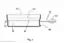
In FIG. 3, one illustrates a schematic drawing of a filter driven by pressurized air. A filter is usually composed by two main pieces: upper bells 17 and mold 18. The upper bell 17 is a container large enough for holding the amount of pulp 4 of a filtration operation; one inserted into it a feed tube 19, which has a coupled diaphragm 19a, which automatically closes when the upper bell 17 is pressurized. Also at this upper bell 17 there is an inlet 20 for compressed air and a safety manometer.
The mold 18 is a reinforced piece having, at its bottom, a thin web 22 and a lower container for collecting residual pulps 23, in which a tube 24 is installed for discharging such pulps. Between the upper bell 17 and the mold 18 there are moveable claws 25 intended for joining or disjointing the joining of both pieces.
In filtration operations, the pulp 4, the volume of which is previously measured, is introduced in the machine through a feed tube 19 until the desired amount is reached. Compressed air under controlled pressure is injected, which will actuate the diaphragm 19a, closing it and pressurizing the upper bell 17. The pressure then forces the passage of the liquids through the single outlet, which is the web 22 situated below the mold 18, forming a filtered cake on said web 22, and the residual pulp flows through the lower container 23, being discharged by the outlet tube 24.
The filtration process ends when only compressed air comes out of the outlet tube 24. At this moment, the compressed-air inlet should be closed, disjointing the movable claws 25, the upper bell 17 and the filtered piece should be removed.
The mold 18 may have any shape, as long as it can hold the pulp volume, which comprises the microfibers and the binding component(s). The containers 17 and 23 may have any shape that is useful for the equipment, that is, they may have a space corresponding to the pulp volume that is to be worked on. The web 22 is preferably very thin in order to promote better retention of the liquid, yielding a product with less water, but the aperture of the web mesh may vary according to the final product that is to be obtained. By preference, a web made of stainless steel in meshes ranging from 60 to 200 mesh-tyler is used.
The mold 18, as well as the bell 17, have particularly rectangular shape, with dimensions on the order of 1.40×0.70 m, being hermetic to leakages of liquids or compressed air. They consist of robust pieces, of steel, at least 5 mm thick, made to bear high pressures. The movable claws 25 are very resistant pieces, being constructed to bear pressures higher than 15 tons.
4.3 Third Variation of Equipment—Vacuum Filtration Process
The vacuum filtration process is an intermediate process, wherein the vacuum causes acceleration of the filtration process. This operation consists of the forced passage of the pulp through partitions having small bores of less than 0.30 mm. Such partitions may be of steel, organic materials like fabrics, sleeves or plastic webs, or else papers suitable for filtration.
In a closed chamber, located below the partition, vacuum is applied, so as to bring about suction of the pulp through the partition. The microfibers are retained on the partition, and the other liquids are let through the newly formed cake, settling in the lower chamber. The processes end when the whole overlying liquid has been sucked and only air passes through the filtered cake.
With these mechanisms, the vacuum is generated by a conventional vacuum pump. For dynamism and rapidity of the process, the industrial plant should have a reservoir where large volumes are accumulated with difference in negative pressure.
At the end of the filtration, the microfibers become a wet cake with some consistency (density on the order of 0.8 to 1.0 g/cm3), which enables the handling thereof on special trays. On the other hand, the mixture containing water and the binding component(s) resulting from the filtration is eliminated or recovered for recirculation.
In FIG. 4, a schematic drawing of a vacuum-actuated filter is illustrated. It is basically composed of three main pieces: a pulp reservoir 26, a mold 27 and the vacuum chamber 29.
The reservoir 26 is a container totally open at its upper part, sufficiently large to hold the amount of pulp of a filtration operation, which is coupled to the mold 27 at its lower part. The mold 27 is closed at its lower part by means of a partition 28, which may be, for example, a very thin screen. Below the partition 28 there is a closed chamber, called vacuum chamber 29, which has a coupled diaphragm 30 that automatically closes when vacuum is applied to the chamber. In order to bring about vacuum in the chamber 29, it is necessary to introduce a vacuum conduit 31, which can make the communication between the chamber 29 and the vacuum reservoir 32. In the chamber 29, a vacuum gauge 33 may be installed for better operational control over the filtration.
In filtration operations, the pulp 4, the volume of which is previously measured, the reservoir 26 until the pre-established amount if reached is introduced. Vacuum is applied through the conduit 31, which causes a difference in negative pressure in the vacuum chamber 29, which in turn causes the diaphragm 30 to close, thus depressurizing the vacuum chamber 29. The vacuum then causes suction of the liquids, forcing them to pass through the partition 28, situated below the mold 27, forming a filtered cake on said partition 28, throughout the mold 27. The residual liquids remain accumulated in the vacuum chamber 29.
The filtration operation ends when there is no more overlying liquid over the filtered cake. At this moment, by turning off the vacuum by means of a meter placed at the vacuum conduit 31, the vacuum chamber 29 is now under atmospheric pressure, releasing the diaphragm 30 and allowing the accumulated liquids to flow out.
The filtered cake may then be removed from the mold. For this purpose it is necessary to use mechanisms for turning the whole equipment with removal by gravity of the cake on special trays.
The mold 27 may have any shape, provided that it will hold the pulp volume that comprises the microfibers and the binding component(s). Particularly, the mold 27 has a rectangular shape with dimensions on the order of 1.40 m×0.70 m. The container 26 may have any shape that is useful for the equipment, that is, it may represent a space corresponding to the pulp volume that is to be worked on. The partition 28, by preference, is a stainless-steel web in meshes from 60 to 200 mesh-tyler.
The filtration operation does not imply settling processes, differing from the latter by its rapidity, and it is often possible to obtain filtered pieces at intervals shorter than 3 minutes, depending upon the degree of automation and adjust of the operations.
Claims
1. A microfibrous composition comprising:
microfibrous siliceous spicules of spongiaria constituted by at least 98% of silicon dioxide with average length of 200 μm and average thickness of 10 μm in an amount ranging from 70% to 99%, by weight, and
at least a binding component in an amount ranging from 1% to 30%, by weight, the amounts based on the total weight of the composition.
2. A microfibrous composition according to claim 1, characterized by comprising an amount of siliceous spicules of spongiaria ranging from 90% to 99% by weight, based on the total weight of the composition.
3. A microfibrous composition according to claim 2, characterized by comprising an amount of siliceous spicules of spongiaria ranging from 90% to 96% by weight, based on the total weight of the composition.
4. A microfibrous composition according to claim 1, characterized by the fact that the microfibers have a specific weight ranging from 2.0 to 2.2 g/cm2.
5. A microfibrous composition according to claim 1, characterized by the fact that the microfibers have a length-to-thickness ratio ranging from 10 to 20.
6. A microfibrous composition according to claim 1, characterized by the fact that the microfibers are essentially constituted by silicon dioxide.
7. A microfibrous composition according to claim 1, characterized by the fact that the microfibers are transparent.
8. Microfibrous composition according to claim 1, characterized by comprising an amount of binding component ranging from 1% to 10% by weight, based on the total weight of the composition.
9. A microfibrous composition according to claim 1, characterized by the fact that the binding component is selected from the group consisting of: aluminous clay, kaolinic clay, spectitic clay, mixed clay, colloidal clay and silicic acid.
10. A microfibrous composition according to claim 1, characterized by having a melting temperature ranging from 1250 to 1760° C.
11. A microfibrous composition according to claim 1, wherein the composition has an apparent specific mass ranging from 0.06 to 1.20 g/cm3.
12. A microfibrous composition according to claim 11, wherein the composition has an apparent specific mass ranging from 0.40 to 0.60 g/cm3.
13. A microfibrous composition according to claim 12, wherein the composition has an apparent specific mass of 0.50 g/cm3.
14. A microfibrous composition according to claim 1, wherein the composition has a porosity ranging from 45 to 95%.
15. A microfibrous composition according to claim 14, wherein the composition has a porosity of 70%.
16. A microfibrous composition according to claim 1, wherein the composition undergoes a curing process.
17. A process for obtaining a microfibrous composition, characterized by comprising the following steps:
a—mixing microfibers comprising microfibrous siliceous spicules of spongiaria with average length of 200 μm and average thickness of 10 μm with water and at least one binding component in an attrition tank;
b—stirring said mixture until a homogeneous pulp is reached;
c—shaping the pulp in a shaping equipment to eliminate the excess water and binding component and to obtain a residual cake;
d—curing the residual cake by a curing process, obtaining the microfibrous composition.
18. A process according to claim 17, characterized in that, in the shaping equipment, the pulp undergoes a settling process.
19. A process according to claim 18, characterized in that the settling process is a simple-type settling process.
20. A process according to claim 18, characterized in that the settling process is a vibration-type settling process.
21. A process according to claim 17, characterized in that, in the shaping equipment, the pulp undergoes a pressure-filtration process.
22. A process according to claim 17, characterized in that, in the shaping equipment, the pulp undergoes a vacuum-filtration process.
23. A process according to claim 17, characterized in that the curing process is a drying in oven.
24. A process according to claim 17, characterized in that the curing process is drying in open air.
25. A process according to claim 17, characterized in that the curing process is a calcination in furnace.
26. A process according to claim 17, characterized in that the microfibrous composition undergoes a firing process.
27. A process according to claim 26, characterized in that the temperature of the firing process is higher than 800° C.
28. A process according to claim 26, characterized in that, after the microfibrous composition undergoes the firing process, it undergoes a grinding process.
29. A process according to claim 28, characterized in that the grinding of the microfibrous composition is carried out with diamond saws.
30. A process according to claim 28, characterized in that the grinding of the microfibrous composition is carried out with grinding wheels.
Images & Drawings included:
Sources:
- United States Patent and Trademark Office - verify current appl. status at the USPTO↗
Recent applications in this class:
- » 20250128981 2025-04-24
HIGH PERFORMANCE FIBERGLASS COMPOSITION - » 20250115514 2025-04-10
HIGH PERFORMANCE FIBERGLASS COMPOSITION WITH IMPROVED ELASTIC MODULUS - » 20250115513 2025-04-10
HIGH PERFORMANCE FIBERGLASS COMPOSITION - » 20250109061 2025-04-03
GLASS COMPOSITION FOR GLASS FIBERS, GLASS FIBERS, GLASS FIBER TEXTILE, AND GLASS FIBER-REINFORCED RESIN COMPOSITION - » 20250109060 2025-04-03
GLASS FIBERS - » 20250059082 2025-02-20
GLASS FIBER - » 20250034032 2025-01-30
GLASS FIBER, GLASS FIBER MANUFACTURING METHOD, AND GLASS - » 20240417316 2024-12-19
GIass Compositions, Fiberizable Glass Compositions, and Glass Fibers Made Therefrom - » 20240417315 2024-12-19
Glass composition for glass fibers, glass fibers, woven glass fiber fabric, and glass-fiber-reinforced resin composition - » 20240417314 2024-12-19
GLASS COMPOSITION FOR GLASS FIBERS, GLASS FIBER, GLASS FIBER WOVEN FABRIC, AND GLASS-FIBER-REINFORCED RESIN COMPOSION