Apparatus and method for strobe charging
US20070201855A1
2007-08-30
11/365,778
2006-02-28
✅ Patent granted
US 7,522,832 B2
2009-04-21
-
-
Melissa J Koval
2027-06-15
Abstract:
An apparatus and method for strobe charging is disclosed. The apparatus and method can dynamically adjust a charging current according to current power level of a battery, thereby stabilizing the operating voltage of the battery and thus using the battery power to the full. The apparatus and method employs a control circuit to detect the current power level of the battery, and dynamically adjusts the charging current, generated from the battery, according to the detected current power level.
Inventors:
- Shi Chen Liu 1 🇹🇼 Hsinchu City, Taiwan
- Chien Kuo Hsu 1 🇹🇼 Hsinchu City, Taiwan
- Shi Chen Liu 1 🇹🇼 Hsinchu, Taiwan
- Chien Kuo Hsu 1 🇹🇼 Hsinchu, Taiwan
Assignee:
- HON HAI PRECISION INDUSTRY CO., LTD. 2,357 🇹🇼 Tu-Cheng, Taipei Hsien, Taiwan
Interested in similar patents?
Get notified when new applications in this technology area are published.
Classification:
G03B7/26 IPC
Control of exposure by setting shutters, diaphragms or filters, separately or conjointly Power supplies; Circuitry or arrangement to switch on the power source; Circuitry to check the power source voltage
G03B7/24 IPC
Control of exposure by setting shutters, diaphragms or filters, separately or conjointly automatically in accordance with markings or other means indicating film speed or kind of film on the magazine to be inserted in the camera
H05B39/00 IPC
Circuit arrangements
H05B39/00 IPC
Circuit arrangements or apparatus for operating incandescent light sources
H05B41/14 IPC
Circuit arrangements or apparatus for igniting or operating discharge lamps Circuit arrangements
H04N5/222 IPC
Details of television systems Studio circuitry; Studio devices; Studio equipment ; Cameras comprising an electronic image sensor, e.g. digital cameras, video cameras, TV cameras, video cameras, camcorders, webcams, camera modules for embedding in other devices, e.g. mobile phones, computers or vehicles
H04N5/225 IPC
Details of television systems; Studio circuitry; Studio devices; Studio equipment ; Cameras comprising an electronic image sensor, e.g. digital cameras, video cameras, TV cameras, video cameras, camcorders, webcams, camera modules for embedding in other devices, e.g. mobile phones, computers or vehicles Television cameras ; Cameras comprising an electronic image sensor, e.g. digital cameras, video cameras, camcorders, webcams, camera modules specially adapted for being embedded in other devices, e.g. mobile phones, computers or vehicles
G03B15/0447 » CPC main
Special procedures for taking photographs; Apparatus therefor; Illuminating scene; Combinations of cameras with lighting apparatus; Flash units; Combinations of cameras with non-electronic flash apparatus; Non-electronic flash units; Constructional details of the flash apparatus; Arrangement of lamps, reflectors, or the like Energy sources; Batteries; Capacitors
G03B15/03 IPC
Special procedures for taking photographs; Apparatus therefor; Illuminating scene Combinations of cameras with lighting apparatus; Flash units
Description
BACKGROUND OF INVENTION1. Field of the Invention
The present invention relates in general to strobe charging, and more particularly to an apparatus and method for strobe charging which can dynamically adjusts a charging current according to current power level of a battery.
2. Description of the Prior Art
In a still image capture system, such as a camera, a strobe is commonly used to provide sufficient light source for image capturing. The strobe needs charging each time before use, and it is typical to employ a power supply unit (e.g. a battery) for providing a charging current to the strobe.
In prior arts, a constant charging current is used. However, if the battery is kept at providing the constant charging current, the operating voltage of the battery will lower rapidly following the power level decrease of the battery. This effect will become more serious when the battery power level is low. When the operating voltage lowers to a certain value, the battery cannot provide electric power any more, even though there is surplus power in the battery. This will cause the inefficiency and waste of the battery power.
SUMMARY OF INVENTIONIn view of this, an object of the present invention is to provide an apparatus and method for strobe charging which can stabilize the operating voltage of the battery in the process of strobe charging, and thus use the battery power to the full, thereby extending the battery life.
According to one embodiment of this invention, a strobe charging apparatus is provided. The strobe charging apparatus comprises: a power supply unit for generating a charging current; a control circuit for detecting a current power level of the power supply unit, and dynamically adjusting the charging current according to the current power level; and a strobe module charged by the charging current.
According to another embodiment of this invention, a strobe charging method is provided. The strobe charging method comprises the steps of: generating a charging current for charging a strobe module by a power supply unit; detecting a current power level of the power supply unit; and dynamically adjusting the charging current according to the current power level.
BRIEF DESCRIPTION OF THE DRAWINGSFIG. 1 is a block diagram of a preferred embodiment of the strobe charging apparatus according to the present invention.
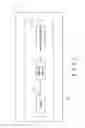
FIG. 2 is a more detailed block diagram of the strobe charging apparatus of FIG. 1.
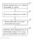
FIG. 3 is a flow chart of a preferred embodiment of the strobe charging method according to the present invention.
DETAILED DESCRIPTIONFIG. 1 is a block diagram of a preferred embodiment of the strobe charging apparatus according to the present invention. As shown in FIG. 1, the strobe charging apparatus 10 is built in a camera 1, and comprises a battery 11, a control circuit 12, and a strobe module 13. The battery 11 generates a charging current for charging the strobe module 13. The battery 11 has a plurality of power level ranges, each of which is corresponding to a charging current value. In one embodiment, a lower power level range is corresponding to a smaller charging current value. In this manner, when the power level of the battery 11 lowers, a smaller charging current is generated so as to keep the operating voltage of the battery 11 stable and use the battery power to the full.
The control circuit 12 is coupled to the battery 11, and detects the current power level of the battery 11. The control circuit 12 determines which power level range the current power level lies in, and dynamically adjusts the charging current to the corresponding charging current value. The adjusted charging current is then used to charge the strobe module 13.
FIG. 2 is a more detailed block diagram of the strobe charging apparatus 10 of FIG. 1. As shown in FIG. 2, the control circuit 12 includes a digital signal processing (DSP) unit 121 and a variable impedance unit 122. The DSP unit 121 detects the current power level of the battery 11, and generates a control signal accordingly. The variable impedance unit 122 transmits the charging current from the battery 11 to the strobe module 13. The impedance of the variable impedance unit 122 is adjusted according to the control signal provided by the DSP unit 121. In one embodiment, the DSP unit 121 detects the current power level and generates the control signal by executing, a firmware program. In another embodiment, the variable impedance unit 122 includes a circuit composed of resistors and switches. The impedance of the variable impedance unit 122 is then adjusted by changing ON/OFF states of the switches according to the control signal.
FIG. 3 is a flow chart of a preferred embodiment of the strobe charging method according to the present invention. The preferred embodiment is applied to the strobe charging apparatus 10 of FIG. 1. As shown in FIG. 3, the flow comprises the steps of:
31 generating the charging current for charging the strobe module 13 by the battery 11;
32 detecting the current power level of the battery 11;
33 determining which power level range the current power level lies in; and
34 dynamically adjusting the charging current to the corresponding charging current value according to the determination of step 33.
By means of the embodiments described above, the strobe charging apparatus and method of the present invention can dynamically adjust a charging current from a battery to a proper value according to the current power level of the battery. Thus, the user can keep the operating voltage of the battery stable in the process of strobe charging, thereby utilizing the battery power to the full and extending the battery life.
While the present invention has been shown and described with reference to the preferred embodiments thereof and in terms of the illustrative drawings, it should not be considered as limited thereby. Various possible modifications and alterations could be conceived of by one skilled in the art to the form and the content of any particular embodiment, without departing from the scope and the spirit of the present invention.
Claims
What is claimed is:1. A strobe charging apparatus comprising:
a power supply unit for generating a charging current;
a control circuit for detecting a current power level of the power supply unit, and dynamically adjusting the charging current according to the current power level; and
a strobe module charged by the charging current.
2. The strobe charging apparatus of claim 1, wherein the power supply unit is a battery.
3. The strobe charging apparatus of claim 1, wherein the power supply unit comprises a plurality of power level ranges, each of which is corresponding to a charging current value.
4. The strobe charging apparatus of claim 3, wherein if the control circuit detects that the current power level lies in one of the power level ranges, the control circuit adjusts the charging current to the corresponding charging current value.
5. The strobe charging apparatus of claim 3, wherein a lower one of the power level ranges is corresponding to a smaller charging current value.
6. The strobe charging apparatus of claim 1, wherein the strobe charging apparatus lies within a still image capture system.
7. The strobe charging apparatus of claim 6, wherein the still image capture system is a camera.
8. The strobe charging apparatus of claim 1, wherein the control circuit comprises:
a digital signal processing (DSP) unit for detecting the current power level of the power supply unit and generating a control signal accordingly; and
a variable impedance unit coupled between the power supply unit and the strobe module, wherein an impedance of the variable impedance unit is adjusted according to the control signal.
9. The strobe charging apparatus of claim 8, wherein the DSP unit detects the current power level and generates the control signal by executing a firmware program.
10. The strobe charging apparatus of claim 8, wherein the variable impedance unit comprises a circuit composed of resistors and switches, wherein the impedance of the variable impedance unit is adjusted by changing ON/OFF states of the switches according to the control signal.
11. A strobe charging method comprising:
generating a charging current for charging a strobe module by a power supply unit;
detecting a current power level of the power supply unit; and
dynamically adjusting the charging current according to the current power level.
12. The strobe charging method of claim 11, wherein the power supply unit is a battery.
13. The strobe charging method of claim 11, wherein the power supply unit comprises a plurality of power level ranges, each of which is corresponding to a charging current value.
14. The strobe charging method of claim 13, wherein the step of dynamically adjusting the charging current comprises:
adjusting the charging current to the corresponding charging current value if the current power level is detected to lie in one of the power level ranges.
15. The strobe charging method of claim 11, wherein a lower one of the power level ranges is corresponding to a smaller charging current value.
Images & Drawings included:


Sources:
- United States Patent and Trademark Office - verify current appl. status at the USPTO↗
Similar patent applications:
Recent applications in this class:
- » 20200218134 2020-07-09
FLASH DEVICE SYSTEM - » 20110129208 2011-06-02
Camera - » 20070232156 2007-10-04
Battery contact mechanism, battery receiving structure, electric power unit, electronic equipment, and pressure-contacting mechanism - » 20050197003 2005-09-08
Battery contact mechanism, battery receiving structure, electric power unit, electronic equipment, and pressure-contacting mechanism
Recent applications for this Assignee:
- » 20110101832 2011-05-05
SECURING MECHANISM AND ELECTRONIC DEVICE ENCLOSURE USING THE SAME - » 20110096516 2011-04-28
SUPPORTING ASSEMBLY FOR PRINTED CIRCUIT BOARD - » 20110096473 2011-04-28
Electronic device - » 20110093746 2011-04-21
System and method for determining display function of BIOS error information - » 20110073276 2011-03-31
Heat dissipation system - » 20110051364 2011-03-03
Securing apparatus for expansion cards - » 20110031987 2011-02-10
System resistance simulating apparatus - » 20100329654 2010-12-30
Lens driving apparatus with anti-shake mechanism - » 20100328789 2010-12-30
Lens module - » 20100321879 2010-12-23
Hard disk drive holder