Flow-controlled wind rotor
US20070201981A1
2007-08-30
10/599,965
2005-04-12
✅ Patent granted
US 7,665,966 B2
2010-02-23
WO; PCT/PL2005/000026; 20050412
WO; WO2005/100785; 20051027
Edward Look | Dwayne J White
2026-05-29
Abstract:
Disclosed in a wind rotor (1) comprising one or more blades (3) rotating around a vertical, central axis (4) within a main bearing (5), said blades being parallel to said vertical axis (4), said blades being connected via crossbars (6), said blades being disposed freely rotatably in bearings (7), and said blades being orientable by means of a wind vane (9). Said blades (3) comprise a symmetrical aerodynamic profile (8) over their entire cross-section. Said rotor comprises a primary control mechanism (11), which is controlled by said wind vane (9) and aligns said profiles (8) of said blade(s) (3) along the wind direction (10) at each point of their trajectory (13) around the central vertical axis (4), said blades being disposed on said crossbars (6), and a secondary control mechanism (12), which aligns the longitudinal axes of said profiles (8) of said blade(s) (3) to the wind (10) at each point of their trajectory (13) around the central vertical axis (4) so as to produce an optimum aerodynamic force depending on the rotation angle of the crossbars (6) with respect to the wind vane (9) and the rotation velocity of the crossbars (6).
Assignee:
- VENTUS Spolka ZOO 1 🇵🇱 Gorzow Wlkp., Poland
- Ventus Spolka ZO.O 1 🇵🇱 Gorzow, Poland
Interested in similar patents?
Get notified when new applications in this technology area are published.
Classification:
F03D3/068 » CPC main
Wind motors with rotation axis substantially perpendicular to the air flow entering the rotor ; Rotors; Construction the wind engaging parts having a cyclic movement relative to the rotor during its rotation the cyclic relative movement being coupled to the movement of rotation; Controlling same, e.g. according to wind direction or force
F03B17/067 » CPC further
Other machines or engines using liquid flow , e.g. of swinging-flap type with rotation axis substantially at right angle to flow direction the flow engaging parts having a cyclic movement relative to the rotor during its rotation the cyclic relative movement being positively coupled to the movement of rotation
F05B2240/214 » CPC further
Components; Rotors for wind turbines with vertical axis of the Musgrove or "H"-type
F05B2260/72 » CPC further
Function; Adjusting of angle of incidence or attack of rotating blades by turning around an axis parallel to the rotor centre line
F05B2260/79 » CPC further
Function; Adjusting of angle of incidence or attack of rotating blades Bearing, support or actuation arrangements therefor
Y02E10/20 » CPC further
Energy generation through renewable energy sources Hydro energy
Y02E10/20 » CPC further
Energy generation through renewable energy sources Hydro energy
Y02E10/30 » CPC further
Energy generation through renewable energy sources Energy from the sea, e.g. using wave energy or salinity gradient
Y02E10/30 » CPC further
Energy generation through renewable energy sources Energy from the sea, e.g. using wave energy or salinity gradient
Y02E10/74 » CPC further
Energy generation through renewable energy sources; Wind energy Wind turbines with rotation axis perpendicular to the wind direction
Y02E10/74 » CPC further
Energy generation through renewable energy sources; Wind energy Wind turbines with rotation axis perpendicular to the wind direction
B63H1/06 IPC
Propulsive elements directly acting on water of rotary type with rotation axis substantially at right angles to propulsive direction with adjustable vanes or blades
F03B13/18 IPC
Adaptations of machines or engines for special use; Combinations of machines or engines with driving or driven apparatus ; Power stations or aggregates characterised by using wave or tide energy using wave energy using the relative movement between a wave-operated member, and another member, where the other member, i.e. rem is fixed, at least at one point, with respect to the sea bed or shore
Description
The invention concerns a flow-controlled wind rotor adjustable by a wind vane and having a vertical axis of rotation and rotating blades revolving around the axis.
DESCRIPTION OF THE PRIOR ARTWind rotors with vertical rotation axes are known in the art as Savonius rotors, Darrieux rotors, vertical dual rotors, or Jackson rotors. Jackson rotors have not only a vertical axis, but comprise also blade-like plates, revolving around the vertical axis and simultaneously turning around their own axis by 180°.
Based on the design of Jackson rotors, solutions have been developed and described, e.g., in specifications of German Patents DE 198 47 469 A, DE 81 119 10 U1 and DE 39 18 184A1.
The invention disclosed in DE 30 18 211 C2 has a design similar to that of a Darrieux rotor. This rotor includes, however, blades having only a limited movement. The efficiency of Darrieux rotors is low. They require strong winds and frequently an auxiliary starter.
Wind motors most commonly-used in practice employ rotors having a horizontal axis of rotation and propeller-like blades rotating around that axis.
Rotor blades working based on this principle are much flatter at the outside than near the axis of rotation. They use as little as 16 to 27% of the theoretically-available wind energy. A support tower for wind rotors which revolve around a horizontal axis must be higher than for rotors revolving around a vertical axis of rotation. The blades working like a propeller move unevenly to the wind flow along their entire length. They are slower near the axis than at the edges of the blades. This results in considerable noise and a poor use of the working area of the blade.
In the specification DD 232 959 A1 described is a rotor for wind motors having a vertical axis, wherein an unsymmetrical design has been used allowing for automatic or forced adjustments of the angles of attack at any time during operation so that the aerodynamic forces constantly change to keep the direction of rotation invariant. With the increase of wind power and the change of the angles of attack of the rotor blades, the number of revolutions will decrease, and aerodynamic forces will drop to around zero. The blades of this wind motor are on one hand fixedly interconnected by means of gears and timing belts, on the other hand, however, are freely movable to allow them to adjust, with their special aerodynamic profile, automatically and optimally to the direction of the wind. Still, it is not discernable how the basic orientation of the rotor blades can change to follow the direction of the wind so as to enable the wind motor to start automatically.
OBJECTIVE OF THE INVENTIONAn objective of the invention is to create a flow-controlled rotor with a vertical axis of rotation, using the power of wind aerodynamically and most efficiently, having a relatively simple control mechanism, and being adjustable and controllable by means of a wind vane.
This objective has been accomplished with features of claim 1. Futher embodiments and beneficial improvements are the subjects of the other claims.
The rotor is used to drive a wind motor and comprises one or more blades rotating around a central vertical axis of rotation, which are oriented parallel to the vertical axis, linked by crossbars, and freely rotatable. The blade have a full-length symmetric and aerodynamic cross-sectional profile and are adjustable to the wind direction by means of a wind vane.
The blades are controlled at each point of their trajectory of movement around the central vertical axis of rotation by a primary and a secondary control mechanisms in a way so that they are powered by a steam of air (wind) with the greatest aerodynamic efficiency.
The primary control mechanism orients the profile of the crossbar-disposed blade(s) in the direction of the wind at each point of the trajectory around the central vertical axis as controlled by the wind vane, and the secondary control mechanism orients the crossbar-disposed blade(s) to the wind with their longitudinal axes depending on the angle of rotation of the crossbars with respect to the wind vane and the speed of rotation of the crossbars at each point of the trajectory around the central vertical axis of rotation, so that the blade(s) produce an optimum aerodynamic force at each point of the trajectory.
The secondary control mechanism is thereby subordinate to the primary control mechanism, which controls the basic alignment to the direction of the wind.
To produce a continuous torque, the profile of the rotor's blades is always so oriented to the wind direction during the path of rotation around the vertical axis so as to attain the optimal uplift pressure, with the pitch angle being adjusted to the direction of the wind plus or minus a certain degree depending on the angle of rotation.
motors may be placed on a tower, a building or in areas of advantageous wind flow.
The invention features may be analogically applied to a water turbine, wherein the torque is hydrodynamically produced to the direction of rotation.
EXAMPLESThe invention is explained hereinbelow more closely in its preferred embodiments on the basis of the drawings.
It shows:
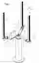
FIG. 1 An isometric overview of the wind motor with a flow-controlled rotor,
FIG. 2 An illustration of the proper shape of control mechanisms for blade alignment,
FIG. 3 A schematic illustration of the blade control depending on the angle of rotation in two selected positions.
The wind motor in FIG. 1 comprises of a tower 2, with a wind rotor 1 rotationally disposed on the main bearing 5. The wind rotor 1 comprises three blades 3 rotating around a central vertical axis 4, the blades being parallel to the vertical axis 4 and connected by crossbars 6. The blades 3 are disposed freely rotatably in the bearings 7 at the ends of the crossbars 6. The blades 3 revolve firstly with the crossbars 6 around the central vertical axis of rotation 4, and secondly around themselves in the bearings 7 at the ends of the crossbeams 6. The blades 3 exhibit in their cross-section at their full length a symmetric aerodynamic profile 8 similar to that of the wing area of a plane.
A wind vane 9 for detecting the direction of the wind 10 is disposed concentrically on the central axis 4 in the main bearing 5 on the tower 2.
The blades 3 controlled by the primary and secondary control mechanisms 11 and 12 revolve with their bearings 7 around the vertical axis 4 on a circular trajectory 13 so that the blade profiles 8 are always oriented parallel to the direction of the wind 10 plus or minus a certain amount for an optimal pitch angle with respect to the direction of the wind as reported by the wind wave 9.
The proper shape of the control mechanisms 11 and 12 for aligning the blades of the wind rotor 3 is shown in FIG. 2.
On the tower 2 of the wind motor disposed is the wind rotor 1 being rotatable around the central vertical axis 4 by means of the main bearing 5.
In front of the main bearing 5 of the wind motor rotor 1 is a crossbar 6, shortened in the surface of the drawing, and a second crossbar 6 marked leaning to the back.
Inside the bushing of the main bearing 5, there is a wind vane 9 with a three-leveled groove pulley 14 disposed concentrically with respect to the main bearing 5 being independent therefrom. From each level of the groove pulley 14 leads a v-belt along each of the crossbars 6 to the blade 3. This v-belt drive 14 comprises the first control mechanism 11 which aligns the blades 3 at each point of their trajectory 13 parallel to the wind vane 9. The blade bearings 7 of each of the blades 3 are for this reason fastened to the crossbars 6 each at a different height.
Inside each of the blade bearings 7, there is a stepping engine 15, which, acting as the secondary control mechanism 12, shifts via a worm gear each blade 3 to a certain positive or negative extent with respect to the direction parallel to the wind vane 9 so as to attain an optimal angle of wind attack.
The primary control mechanism 11 aligns the blades 3 with their profiles 8 by means of the wind vane 9 along the direction of the wind 10 at each point along the blades' trajectory around the central vertical axis of rotation 4.
To execute the two independent rotational movements in the blade bearings 7, the blade bearings comprise also two concentrically-disposed and independently-rotating bearing bushings.
The secondary control mechanism 12, dependent on the primary control mechanism 11, aligns each blade 3 disposed on its crossbar 6 with the wind 10 at each point of trajectory 13 around the central horizontal axis 4, so that depending on the angle of rotation of each crossbar 6 with respect to the wind vane 9, each blade 3 is aligned with the longitudinal axis of its profile 8 at each point of its trajectory 13 so as to produce an optimum aerodynamic force.
Besides, the blades 3 are aligned to the wind based on the rotation velocity of the crossbars 6, which changes with the wind velocity 10, in a way that keeps the rotation velocity approximately constant and prevents the overload of the engine.
FIG. 3 shows schematically the control of blades 3 dependent on their angle of rotation in two selected positions 3 and 3′ of their trajectory 13 around the vertical axis of rotation 4. The work angles of the blade profiles 8 are different from one another and depend on each point of their trajectory 13, and can assume both negative and positive values with respect to the direction of the wind 10, which produces the wind force Fw, so that the propulsion FA at each rotation angle of the blade 3 fluctuates continually between negative and positive values, so that the resultant force FT always assumes the positive values in the direction of rotation.
LIST OF REFERENCE NUMBERS
- 1 Wind rotor
- 2 Tower
- 3 Rotor blade
- 4 Central vertical axis
- 5 Central main bearing
- 6 Horizontal crossbars
- 7 Blade bearing
- 8 Symmetric aerodynamic profile
- 9 Wind vane
- 10 Wind direction
- 11 Primary control mechanism
- 12 Secondary control mechanism
- 13 Circular trajectory of the blade
- 14 Groove pulley
- 15 Stepping engine
Claims
1-7. (canceled)
8. A flow-controlled wind motor rotor (1) comprising one or more blades (3), said blades rotating around a central vertical axis (4) in a main bearing (5), said blades being parallel to the vertical axis (4), said blades being connected via crossbars (6), said blades being disposed freely rotatably in bearings (7), said blades (3) comprising a symmetrical aerodynamic profile (8) over their entire cross-section, said blades being orientable to the direction of the wind (10), and said rotor comprising a wind vane (9) to capture the direction of the wind
characterized in that
said rotor comprises a primary control mechanism (11), which is controlled by said wind vane (9) and aligns said profiles (8) of said blade(s) (3) along the wind direction (10) at each point of their trajectory (13) around the central vertical axis (4), said blades being disposed on said crossbars (6),
said rotor comprises a secondary control mechanism (12), which aligns the longitudinal axes of said profiles (8) of said blade(s) (3) to the wind (10) at each point of their trajectory (13) around the central vertical axis (4) so as to produce an optimum aerodynamic force depending on the rotation angle of the crossbars (6) with respect to the wind vane (9) and the rotation velocity of the crossbars (6), and
said secondary control mechanism (12) is subordinate to the first control mechanism (11).
9. The wind rotor of claim 1, characterized in that the control mechanisms (11, 12) are mechanically, electromechanically, hydraulically or pneumatically controllable.
10. The wind rotor of claim 1, characterized in that the primary control mechanism (11) comprises a V-belt drive, and the secondary control mechanism (12) comprises is a stepping engine (15) with a worm gear.
11. The wind rotor of claim 1, characterized in that said wind vane (9) is disposed concentrically and rotatably in the main bearing (5) on the central vertical axis (4).
12. The wind rotor of claim 1, characterized in that it comprises an electronic wind gauge as an alternative to said wind vane (9).
13. The wind rotor of claim 1, characterized in that said blades (3) are positioned in said bearings (7) on said crossbars (6) with an upward and/or a downward bias.
14. The wind rotor of claim 1, characterized in that said blades (3) are held by said crossbars (6), which crossbars are placed around said central vertical axis (4) at several levels disposed over one another.
15. The wind rotor of claim 9, characterized in that said wind vane (9) is disposed concentrically and rotatably in the main bearing (5) on the central vertical axis (4).
16. The wind rotor of claim 9, characterized in that it comprises an electronic wind gauge as an alternative to said wind vane (9).
17. A wind rotor (1) comprising one or more blade(s) (3) having a first axis of rotation (4) and a second axis of rotation; and a wind vane (9);
wherein
said blade(s) (3) are revolvable around said first axis of rotation on a trajectory (13);
said blade(s) (3) are rotatable around said second axis of rotation; and
when revolving around said first axis of rotation, said blade(s) (3) are oriented substantially in parallel to said wind wane (9) plus or minus a pitch angle, the amount of said pitch angle varying along said trajectory (13).
Images & Drawings included:


Sources:
- United States Patent and Trademark Office - verify current appl. status at the USPTO↗
Recent applications in this class:
- » 20250122861 2025-04-17
VERTICAL AXIS WIND TURBINE - » 20230417219 2023-12-28
Vertical wind turbine comprising a coaxial pitch motor, kit for same, and method for operating same - » 20230287864 2023-09-14
Universal propeller, operating method and favoured use - » 20230160364 2023-05-25
Vertical axis wind turbine - » 20230065477 2023-03-02
IMPROVEMENTS TO FLUID ROTORS WITH ADJUSTABLE VANES - » 20230041054 2023-02-09
Wind turbine power generation system - » 20220112877 2022-04-14
Vertical axis wind turbine - » 20210164439 2021-06-03
Wind power generation device with real time pitch actuation - » 20200208606 2020-07-02
WIND POWER GENERATION DEVICE - » 20200149510 2020-05-14
Vertical wind turbine comprising a coaxial pitch motor, kit for same, and method for operating same