Hair drier
US20070274696A1
2007-11-29
10/569,776
2004-02-16
✅ Patent granted
US 7,801,423 B2
2010-09-21
WO; PCT/BR2004/000010; 20040216
WO; WO2005/023043; 20050317
Daniel Robinson
2026-05-01
Abstract:
“IMPROVED HAIR DRIER” including a housing, inside which an electrical engine is mounted, which activates a rotor generating an axial air flow crossing the equipment and contacting the heating element represented by an electrical resistances, duly mounted in a spacing structures; the housing of the relevant hair drier further incorporates a gripping part from which the electrical cable emerges, thereby allowing to connect the equipment with the electrical network, the gripping part further incorporating keys which control independently both the activation of the electrical engine and also the activation of the electrical resistance, the relevant hair drier is characterized for incorporating an ionizing device, which essentially is a high voltage source with a limited current; the ionizing device is connected with the conventional electrical circuit of the equipment, it being activated simultaneously with the activation of the electrical engine, or further at the time of the conjoint activation of both electrical engine and electrical resistance; from the ionizing device, at least one cable emerges, which is duly insulated by a sheath, and at the end of the cable an active pole x is mounted.
Assignee:
Interested in similar patents?
Get notified when new applications in this technology area are published.
Classification:
A45D20/12 » CPC main
Hair drying devices; Accessories therefor; Hot-air producers heated electrically; Hand-held drying devices, e.g. air douches Details thereof or accessories therefor, e.g. nozzles, stands
A45D2200/202 » CPC further
Details not otherwise provided for in; Additional enhancing means Ionisation
A45D20/10 IPC
Hair drying devices; Accessories therefor; Hot-air producers heated electrically Hand-held drying devices, e.g. air douches
A47J27/00 IPC
Cooking-vessels
A47J27/00 IPC
Cooking; Apparatus for making beverages
Description
The present report describes a hand hair dryer, such as that commonly used in beauty parlors and related establishments, incorporating an improvement which is particularly associated with the incorporation, in said equipment, of a ionizing device producing negative ions.
As it is known by professionals operating in electrical and/or electronic projects, a high voltage source duly installed can emit a great number of negative ions. It is further known by said professionals that a negative ion generator is essentially similar to an electrostatic generator, which is a device producing high voltage.
Based on this functional principle, air-sterilizing devices were launched in the 70's, incorporating internal ionization devices, which provided ionization of the air passing inside the equipment, thereby producing ambient air sterilization effect.
On the other hand, the electrostatic energy is also generated in a natural manner, for example, when hairs are brushed with combs or brushes manufactured in plastic material.
Under such circumstances, friction between the hair and the comb (or brush) induces the electrical load exchange, causing the hair to be loaded with a positive polarity static electricity.
When loaded with a positive load, hairs usually become ruffle or bristly, in a level proportional to the load applied to the same.
To a certain extent, in some cases the static electricity ends up to damage the quality of coiffure, since hairs, when loaded, are likely not to assume the desired arrangement, such a phenomenon being more frequent in dry days, with a few air humidity.
In view of such a disadvantage, the improved air drier under this invention privilege patent has been developed, which incorporates an ionizing device generating negative ions which are drawn by the air draft crossing the equipment and are directed towards user's hair, causing the same to be negatively ionized.
The ionizing effect produced by the proposed hair drier allows possible positive loads present in hairs (responsible for the bristly effect) and generated, for example, by the use of combs or brushes manufactured in plastic material, to be neutralized by negative ions which are administered to the drying air flow through the ionizing device incorporated to the equipment.
In view of the foregoing, one of the objectives of the present invention privilege patent is providing a hair drier incorporating in its structure, in addition to conventional components, such as electrical resistance, electrical engine, turbine or rotor driven by said electrical engine etc., an ionizing device which, as it allows neutralization of occasional positive static loads present in hairs, through generation of negative ions, it may allow to get a better quality in the execution of coiffures in general.
Another objective of the present invention privilege patent is providing a hair drier with a ionizing device which, due to its technical characteristics, presents a total operating safety on the part of the user.
The hair drier under the present invention patent will be described in details in drawings listed below, in which:
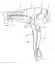
FIG. 1 illustrates a general and schematic view of the relevant hair drier; and
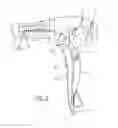
FIG. 2 illustrates a view showing individually the negative ion generating device and the connection thereof with the needle operating as a negative ion emitting pole; said FIG. 2 further counts on an enlarged detail showing specially the negative ion emitting pole.
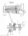
According to illustration of above-mentioned figures, the improved hair drier under the present invention privilege patent comprises a housing 1 inside which an electrical engine 2 is mounted, activating a rotor or turbine 3 which generates an axial air flow crossing the device and contacting the heating element represented by an electrical resistance 4, which is duly mounted in a spacing structure 5.
The housing 1 of the relevant hair drier further incorporates a gripping part 6 from which the electrical cable 7 emerges, allowing to connect the device with the electrical network, said gripping part 6 further incorporating keys 8 which individually control both electrical engine 2 activation and electrical resistance 4 activation; the relevant hair drier is characterized for incorporating an ionizing device 9 which essentially is a high voltage source with a limited current.
The ionizing device 9 is connected with the conventional electrical circuit of the equipment, it being activated simultaneously with activation of the electrical engine 2 or further at the conjoint activation of both electrical motor 2 and electrical resistance 4.
The ionizing device 9 is illustrated in a schematic manner, as in itself it is a very known component.
From the ionizing device 9, at least one cable 10 emerges, which is duly insulated by a sheath 11, said cable 10 passing along the central region of the spacing structure 5, where the electrical resistance 4 is mounted, as illustrated in FIG. 2.
At the end of cable 10 a needle-shaped element 12 is connected, presenting an essentially tapered format, with a sharp-pointed end 13.
Physical configuration of the needle-shaped element 12 can be best noted from the enlarged detail of FIG. 2.
The needle-shaped element 12 configures an active pole X, which is positioned preferably near the previous end of the spacing structure 5, which local coincides with the point with the highest air flow speed crossing the equipment and that therefore presents a higher effectiveness and yield as to improvement of ions produced by device 9.
As it happens with a conventional hair drier, air is admitted by the rear region of housing 1, it being accelerated by rotor 3 and forced to follow by duct defined along said housing 1.
Further in a conventional manner, the air flow reaches the frontal region of the equipment, which presents a slight splay determining the region of a progressive pressure increase and therefore of a higher air flow speed and exactly in that region where the air flow assumes a higher speed, the active pole X is positioned, where the negative ions are generated.
Air drier housing physical configuration as illustrated in FIGS. 1 and 2 should be understood as an example, since the relevant ionizing device can be easily incorporated to other hair drier models.
In the present case, device 9 operates only one active pole X, and such a fact also does not impede the adoption of two or more active poles X, depending on the desired ionization level. needle-shaped element 12 can be best noted from the enlarged detail of FIG. 2.
The needle-shaped element 12 configures an active pole X, which is positioned preferably near the previous end of the spacing structure 5, which local coincides with the point with the highest air flow speed crossing the equipment and that therefore presents a higher effectiveness and yield as to improvement of ions produced by device 9.
As it happens with a conventional hair drier, air is admitted by the rear region of housing 1, it being accelerated by rotor 3 and forced to follow by duct defined along said housing 1.
Further in a conventional manner, the air flow reaches the frontal region of the equipment, which presents a slight splay determining the region of a progressive pressure increase and therefore of a higher air flow speed and exactly in that region where the air flow assumes a higher speed, the active pole X is positioned, where the negative ions are generated.
Air drier housing physical configuration as illustrated in FIGS. 1 and 2 should be understood as an example, since the relevant ionizing device can be easily incorporated to other hair drier models.
In the present case, device 9 operates only one active pole X, and such a fact also does not impede the adoption of two or more active poles X, depending on the desired ionization level.
Claims
1. “IMPROVED HAIR DRIER” comprising a housings, inside which an electrical engine is mounted, which activates a rotor generating an axial air flow crossing the equipment and contacting a heating element represented by an electrical resistance, duly mounted in a spacing structure; the housings of the relevant hair drier further incorporates a gripping part from which an electrical cable emerges, thereby allowing to connect the hair drier with an electrical network, said gripping part further incorporating keys which control independently both activation of the electrical engine and also activation of the electrical resistance, the hair drier further comprising an ionizing device, which is essentially a high voltage source with a limited current; the ionizing device is connected with the drier by a conventional electrical circuit, it being activated simultaneously with the activation of the electrical engine, or further at the time of the conjoint activation of both electrical engine and the electrical resistance; from the ionizing device, at least one cable emerges, which is duly insulated by a sheath, and at an end of the cable an active pole X is mounted.
2. “IMPROVED HAIR DRIER” according to claim 1, wherein the cable passes along a central region of the spacing structure where the electrical resistance is mounted.
3. “IMPROVED HAIR DRIER” according to claim 1, wherein the active pole (X) is configured by a needle-shaped element having an essentially tapered format, with a sharp-pointed end.
4. “IMPROVED HAIR DRIER” according to claim 3, wherein the needle-shaped element configuring the active pole (X) is positioned preferably near a previous end of the spacing structures, which location coincides with a point of highest air flow speed crossing the equipment.
5. “IMPROVED HAIR DRIER” according to claim 1, wherein the relevant drier may incorporate two or more active poles.
Images & Drawings included:
Sources:
- United States Patent and Trademark Office - verify current appl. status at the USPTO↗
Similar patent applications:
- » 20250017347
DOUBLE-DUCT HOT AIR GUIDE STRUCTURE AND HAIR DRIER THEREOF - » 10467573
Gas combustion type hair drier - » 20050229424
Hair drier - » 20060255219
[HAIR DRIER SUPPORT RACK] - » 20070169369
Hair Drier with 3-Dimensional Control Surface - » 20110219636
IMPROVED HAIR DRIER - » 20130263464
Hair drier - » 20150216283
Hair drier - » 20160166036
TOUCH HAIR DRIER - » 10432593
Hair drier with minus ion producer
Recent applications in this class:
- » 20250288078 2025-09-18
SMART HAIR DRYER - » 20250261734 2025-08-21
SYSTEM AND METHOD FOR AN ENHANCED HAIR DRYER - » 20250234974 2025-07-24
ACCESSORY FOR CURLING LOCKS OF HAIR - » 20250221508 2025-07-10
SYSTEM AND METHOD FOR AN ENHANCED HAIR DRYER - » 20250213018 2025-07-03
HEATING ELEMENT & DRYING APPARATUS - » 20250185777 2025-06-12
DRYING APPARATUS - » 20250176695 2025-06-05
SYSTEM AND METHOD FOR AN ENHANCED HAIR DRYER - » 20250176694 2025-06-05
SMART HAIR DRYER - » 20250143433 2025-05-08
HAIR CARE APPLIANCE - » 20250143432 2025-05-08
HAIR STYLING APPLIANCE AND METHOD OF USING SAME
Recent applications for this Assignee:
- » 20090320873 2009-12-31
Accessory for use together with hair dryers