Hinge to improve panel stability
US20080098568A1
2008-05-01
11/582,056
2006-10-16
✅ Patent granted
US 7,533,449 B2
2009-05-19
-
-
Victor Batson | Jeffrey O'Brien
2027-06-23
Abstract:
A hinge to improve panel stability has a central bracket, a tilt hinge assembly and a rotating hinge assembly. The central bracket has two ribs. The tilt hinge assembly connects to the central bracket and connects to a base of an electronic device. The rotating hinge assembly connects to the central bracket, connects to a panel of the electronic device and has a flange abutting against the ribs of the central bracket to keep the panel steady when the panel rotates relative to the base via the rotating hinge assembly.
Assignee:
- SHIN ZU SHING CO., LTD. 60 🇹🇼 Taipei Hsien, Taiwan
Interested in similar patents?
Get notified when new applications in this technology area are published.
Classification:
G06F1/1681 » CPC main
Details not covered by groups - and; Constructional details or arrangements for portable computers; Constructional details or arrangements of portable computers not specific to the type of enclosures covered by groups - ; Miscellaneous details related to the relative movement between the different enclosures or enclosure parts Details related solely to hinges
G06F1/162 » CPC further
Details not covered by groups - and; Constructional details or arrangements for portable computers with several enclosures having relative motions, each enclosure supporting at least one I/O or computing function with folding flat displays, e.g. laptop computers or notebooks having a clamshell configuration, with body parts pivoting to an open position around an axis parallel to the plane they define in closed position changing, e.g. reversing, the face orientation of the screen with a two degrees of freedom mechanism, e.g. for folding into tablet PC like position or orienting towards the direction opposite to the user to show to a second user
H04M1/0212 » CPC further
Substation equipment, e.g. for use by subscribers; Constructional features of telephone sets; Portable telephone sets, e.g. cordless phones, mobile phones or bar type handsets; Portable telephones comprising a plurality of mechanically joined movable body parts, e.g. hinged housings characterized by the relative motions of the body parts using combined folding and rotation motions with a two degrees of freedom mechanism, i.e. folding around a first axis and rotating around a second axis perpendicular to the first
E05D11/1078 » CPC further
Additional features or accessories of hinges; Devices for preventing movement between relatively-movable hinge parts for maintaining the hinge in two or more positions, e.g. intermediate or fully open the maintaining means acting parallel to the pivot
E05Y2900/606 » CPC further
Application of doors, windows, wings or fittings thereof for other use for electronic devices
Y10T16/5404 » CPC further
Miscellaneous hardware [e.g., bushing, carpet fastener, caster, door closer, panel hanger, attachable or adjunct handle, hinge, window sash balance, etc.]; Hinge including means to hold or retard hinged members against pivotal movement [e.g., catch] Pivoted
Y10T16/547 » CPC further
Miscellaneous hardware [e.g., bushing, carpet fastener, caster, door closer, panel hanger, attachable or adjunct handle, hinge, window sash balance, etc.]; Hinge having plural hinge axes [e.g., multiple pintle]
Y10T16/5472 » CPC further
Miscellaneous hardware [e.g., bushing, carpet fastener, caster, door closer, panel hanger, attachable or adjunct handle, hinge, window sash balance, etc.]; Hinge having plural hinge axes [e.g., multiple pintle] having transverse or skewed axes
Y10T16/5515 » CPC further
Miscellaneous hardware [e.g., bushing, carpet fastener, caster, door closer, panel hanger, attachable or adjunct handle, hinge, window sash balance, etc.]; Hinge having stop or abutment comprising relieved axially opposed relatively rotating surfaces
E05D3/10 » CPC further
Hinges with pins with two or more pins with non-parallel pins
Description
BACKGROUND OF THE INVENTION
1. Field of the Invention
The present invention relates to a hinge, especially to a hinge mounted between a panel and a base of an electronic device to improve panel stability.
2. Description of the Prior Arts
Electrical appliances such as notebook computers, cell phones, etc. have a panel, a base and a conventional hinge. The conventional hinge connects the panel to the base along a transverse axis and a longitudinal axis to allow the panel to pivot relative to the base. When the conventional hinge pivots along the transverse axis, the panel is opened or closed relative to the base. When the conventional hinge pivots along the longitudinal axis, the panel is turned left or right relative to the base. The conventional hinge comprises a stationary leaf, a rotating leaf and a contact surface. The stationary leaf connects to the base. The rotating leaf connects to the panel to allow the panel to turn left or right relative to the base. However, the contact surface between the stationary leaf and the rotating leaf is not flat. When the panel is turned left or right relative to the base, the non-flat contact surface between the panel and base easily causes the panel to shake.
To overcome the shortcomings, the present invention provides a hinge to improve panel stability to mitigate or obviate the aforementioned problems.
SUMMARY OF THE INVENTION
The main objective of the present invention is to provide a hinge to improve panel stability. The hinge to improve panel stability has a central bracket, a tilt hinge assembly and a rotating hinge assembly. The central bracket has two ribs. The tilt hinge assembly connects to the central bracket and connects to a base of an electronic device. The rotating hinge assembly connects to the central bracket, connects to a panel of the electronic device and has a flange abutting against the ribs of the central bracket to keep the panel steady when the panel rotates relative to the base via the rotating hinge assembly.
Other objectives, advantages and novel features of the invention will become more apparent from the following detailed description when taken in conjunction with the accompanying drawings.
BRIEF DESCRIPTION OF THE DRAWINGS
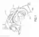
FIG. 1 is a perspective view of a hinge to improve panel stability in accordance with the present invention;
FIG. 2 is another perspective view of the hinge in FIG. 1;
FIG. 3 is an exploded perspective view of the hinge in FIG. 1;
FIG. 4 is another exploded perspective view of the hinge in FIG. 1;
FIG. 5 is a side view of the hinge in FIG. 1;
FIG. 6 is a top view of the hinge in FIG. 1;
FIG. 7 is an end view in partial section of the hinge in FIG. 1 mounted in an electronic device; and
FIG. 8 is an operational end view in partial section of the hinge in FIG. 1 when a panel of the electronic device rotates relative to a base of the electronic device.
DETAILED DESCRIPTION OF THE PREFERRED EMBODIMENTS
With reference to FIGS. 1 to 4, a hinge to improve panel stability in accordance with the present invention comprises a central bracket (10), a tilt hinge assembly (20) and a rotating hinge assembly (30).
The central bracket (10) is U-shaped and has a base (11), a first arm (12) and a second arm (13).
The base (11) has a first end, a second end, two sides, an outer surface, an inner surface, a central hole (111), two ribs (112) and at least one positioning detent (113). The ribs (112) are respectively and perpendicularly formed on the two sides of the base (11) toward the inner surface. The at least one positioning detent (113) is formed in the inner surface of the base (11) around the central hole (111).
The first arm (12) is formed perpendicularly on the first end of the base (11) toward the inner surface of the base (11) and has an outer surface, an inner surface, a central hole (121) and a fastening hole (122). The fastening hole (122) is formed through the first arm (12).
The second arm (13) is formed perpendicularly on the second end of the base (11) toward the inner surface of the base (11) and has an outer surface, an inner surface and a central hole (131).
The tilt hinge assembly (20) connects to the first and second arms (12, 13) of the central bracket (10) and comprises a limiting shaft (21), a rotating positioning element (22), a stationary positioning element (23), a connecting bracket (24), a fastener (25), a stationary rod (26), a limiting bracket (27), a limiting element (28) and multiple washers (29).
The limiting shaft (21) extends through the first arm (12) and has an inner end, an outer end (214) and a limiting head (211). The outer end (214) abuts the outer surface of the first aim (12) and may be a threaded end. The limiting head (211) is formed transversely on the inner end of the limiting shaft (21), abuts the inner surface of the first arm (12) and has two limiting sides (212) and two flat sides (213). The limiting sides (212) are opposite to each other. The flat sides (213) are opposite to each other. The distance between the limiting sides (212) is longer than the distance between the flat sides (213).
The rotating positioning element (22) is mounted securely on the limiting shaft (21), is mounted between the limiting head (211) of the limiting shaft (21) and the inner surface of the first arm (12) and has a contacting surface and at least one positioning detent (221). The contacting surface of the rotating positioning element (22) faces to the inner surface of the first arm (12). The at least one positioning detent (221) is formed in the contacting surface of the rotating positioning element (22).
The stationary positioning element (23) is mounted around the limiting shaft (21), is mounted securely on the first arm (12), is mounted adjacent to the rotating positioning element (22) and has a contacting surface, a fastening surface, at least one positioning protrusion (231) and a fastening protrusion (232). The contacting surface of the stationary positioning element (23) faces to the contacting surface of the rotating positioning element (22). The fastening surface of the stationary positioning element (23) faces to the inner surface of the first arm (12). The at least one positioning protrusion (231) is formed on and extends out of the contacting surface and corresponds to and selectively engages the at least one positioning detent (221) in the rotating positioning element (22). The fastening protrusion (232) is formed on and extends out of the fastening surface of the stationary positioning element (23) and extends through the fastening hole (122) in the first arm (12).
The connecting bracket (24) is mounted securely on the limiting shaft (21) between the outer end (214) of the limiting shaft (21) and the outer surface of the first arm (12).
The fastener (25) is mounted securely on the outer end (214) of the limiting shaft (21) and may be a nut screwed on the outer end (214) of the limiting shaft (21).
The stationary rod (26) is mounted securely in and extends through the second arm (13) of the central bracket (10) and has an inner end, an outer end and multiple fastening protrusions (261). The fastening protrusions (261) are formed axially on the outer end of the stationary rod (26).
The limiting bracket (27) is mounted rotatably on the outer end of the stationary rod (26) and has an outer surface and a stop (271). The stop (271) is formed on the outer surface of the limiting bracket (27).
The limiting element (28) is mounted securely on the outer end of the stationary rod (26), engages the fastening protrusions (261) on the stationary rod (26) and has an edge and an arc limit (281). The arc limit (281) is formed radially on the edge of the limiting element (28) and selectively abuts against the stop (271) on the limiting bracket (27).
The washers (29) are mounted around the limiting shaft (21) and the stationary rod (26) to reduce the friction.
The rotating hinge assembly (30) connects to the base (11) of the central bracket (10) and comprises a rotating rod (31), a rotating positioning element (32), a stationary limiting element (33), a rotating limiting element (34), a fastening bracket (35), a resilient element (36) and multiple washers (37).
The rotating rod (31) is mounted rotatably and extends through the base (11) of the central bracket (10) and has a bottom end, a top end, a flange (311) and multiple fastening protrusions (314). The flange (311) is formed radially on the bottom end of the rotating rod (31), corresponds to the limiting head (211) of the limiting shaft (21) and has a center, a flat side (312) and an arc side (313) adjacent to the flat side (312). The distance between the center and the flat side (312) is shorter than the distance between the center and the arc side (131). The flat side (312) of the flange (311) of the rotating rod (31) alternatively aligns with the limiting side (212) or the flat side (213) of the limiting head (211) of the limiting shaft (21). The arc side (313) of the flange (311) of the rotating rod (31) abuts against the ribs (112) on the base (11) of the central bracket (10) and alternatively aligns with the limiting side (212) or the flat side (213) of the limiting head (211) of the limiting shaft (21). The fastening protrusions (314) are formed axially on the top end of the rotating rod (31).
The rotating positioning element (32) is mounted securely on the rotating rod (31), abuts against the inner surface of the base (11) and has a top surface and at least one positioning protrusion (321). The at least one positioning protrusion (321) is formed on the top surface of the rotating positioning element (32) and selectively engages the at least one positioning detent (113) in the base (11).
The stationary limiting element (33) is mounted rotatably around the rotating rod (31) and has an edge and a limit (331). The limit (331) is formed on and extends radially out of the edge of the stationary limiting element (33).
The rotating limiting element (34) is mounted securely on the rotating rod (31) and has a contacting surface and at least one stop (341). The contacting surface of the rotating limiting element (34) abuts against the stationary limiting element (33). The at least one stop (341) is formed on the contacting surface of the rotating limiting element (34) and corresponds to and selectively abuts against the limit (331) on the stationary limiting element (33).
The fastening bracket (35) is mounted securely on the top end of the rotating rod (31) and engages the fastening protrusions (314) on the rotating rod (31).
The resilient element (36) is mounted around the rotating rod (31) between the rotating positioning element (32) and the flange (311) on the rotating rod (31).
The washers (37) are mounted around the rotating rod (31) to reduce the friction.
With further reference to FIGS. 7 and 8, the hinge in accordance with the present invention is mounted in an electronic device. The electronic device comprises a panel (40) and a base (50). The fastening bracket (35) of the rotating hinge assembly (30) connects to the panel (40). The connecting bracket (24) and the limiting bracket (27) of the tilt hinge assembly (20) connect to the base (50).
With further reference to FIGS. 5 and 6, when the panel (40) rotates via rotating hinge assembly (30), the panel (40) rotates relative to the base (50). The panel (40) drives the rotating rod (31) to rotate relative to the base (11) of the central bracket (10). Because the arc side (313) of the flange (311) of the rotating rod (31) abuts against the ribs (112) on the base (11), the ribs (112) support the rotating rod (31) to keep from shaking. Therefore, the panel (40) is kept steady when the panel (40) rotates relative to the base (50).
When the panel (40) rotates via tile hinge assembly (20), the panel (40) is opened or closed relative to the base (50). The rotating rod (31) of the rotating hinge assembly (30) is rotated relative to the limiting shaft (21) of the tilt hinge assembly (20). When the inside angle between the panel (40) and the base (50) is smaller than 90 degrees, the arc side (313) of the flange (311) of the rotating rod (31) aligns with the limiting side (212) of the limiting head (211) of the limiting shaft (21). The rotating rod (31) is stopped by the limiting shaft (21). Therefore, the panel (40) cannot rotate via the rotating hinge assembly (30) when the inside angle between the panel (40) and the base (50) is smaller than 90 degrees.
Even though numerous characteristics and advantages of the present invention have been set forth in the foregoing description, together with details of the structure and features of the invention, the disclosure is illustrative only. Changes may be made in the details, especially in matters of shape, size, and arrangement of parts within the principles of the invention to the full extent indicated by the broad general meaning of the terms in which the appended claims are expressed.
Claims
What is claimed is:1. A hinge to improve panel stability comprising:
a central bracket having
a base having
a first end;
a second end;
two sides;
an outer surface;
an inner surface; and
two ribs respectively formed perpendicularly on the two sides of the base toward the inner surface of the base;
a first arm formed perpendicularly on the first end of the base toward the inner surface of the base; and
a second arm formed perpendicularly on the second end of the base toward the inner surface of the base;
a tilt hinge assembly connecting to the first and second arms of the central bracket and comprising
a limiting shaft extending through the first arm and having an outer end;
a connecting bracket mounted securely on the limiting shaft;
a fastener mounted securely on the outer end of the limiting shaft;
a stationary rod mounted securely in and extending through the second arm of the central bracket and having an outer end; and
a limiting bracket mounted rotatably on the outer end of the stationary rod; and
a rotating hinge assembly connecting to the base of the central bracket and comprising
a rotating rod mounted rotatably and extending through the base of the central bracket and having
a bottom end;
a top end; and
a flange formed radially on the bottom end of the rotating rod and abutting against the ribs on the base of the central bracket adapted to improve panel stability with abutment of the flange with the ribs; and
a fastening bracket mounted securely on the top end of the rotating rod.
2. The hinge as claimed in claim 1, wherein
the limiting shaft of the tilt hinge assembly has
an inner end; and
a limiting head formed transversely on the inner end of the limiting shaft and having two limiting sides opposite to each other and two flat sides opposite to each other, wherein a distance between the limiting sides is longer than a distance between the flat sides; and
the flange of the rotating rod of the rotating hinge assembly corresponds to the limiting head of the limiting shaft and has
a flat side alternatively aligning with the limiting side or the flat side of the limiting head of the limiting shaft;
an arc side adjacent to the flat side of the rotating rod abutting against the ribs on the base of the central bracket and alternatively aligning with the limiting side or the flat side of the limiting head of the limiting shaft; and
a center, wherein a distance between the center and the flat side of the rotating rod is shorter than a distance between the center and the arc side.
3. The hinge as claimed in claim 2, wherein
the base of the central bracket has
a central hole; and
at least one positioning detent formed in the inner surface of the base around the central hole; and
the rotating hinge assembly further comprises a rotating positioning element mounted securely on the rotating rod, abutting against the inner surface of the base and having
a top surface; and
at least one positioning protrusion formed on the top surface of the rotating positioning element and selectively engaging the at least one positioning detent in the base.
4. The hinge as claimed in claim 3, wherein the tilt hinge assembly further comprises
a rotating positioning element mounted securely on the limiting shaft and having
a contacting surface; and
at least one positioning detent formed in the contacting surface of the rotating positioning element; and
a stationary positioning element mounted around the limiting shaft, mounted securely on the first arm and having
a contacting surface facing to the contacting surface of the rotating positioning element of the tilt hinge assembly;
a fastening surface; and
at least one positioning protrusion formed on and extending out of the contacting surface of the stationary positioning element and corresponding to and selectively engaging the at least one positioning detent in the rotating positioning element of the tilt hinge assembly.
5. The hinge as claimed in claim 4, wherein
the first arm of the central bracket has a fastening hole formed through the first arm; and
the stationary positioning element of the tilt hinge assembly has a fastening protrusion formed on and extending out of the fastening surface of the stationary positioning element and extending through the fastening hole in the first arm.
6. The hinge as claimed in claim 5, wherein
the limiting bracket of the tilt hinge assembly has an outer surface and a stop formed on the outer surface of the limiting bracket; and
the tilt hinge assembly further comprises a limiting element mounted securely on the outer end of the stationary rod, engaging the fastening protrusions on the stationary rod and having
an edge; and
an arc limit formed radially on the edge of the limiting element and selectively abutting against the stop on the limiting bracket.
7. The hinge as claimed in claim 6, wherein the rotating hinge assembly further comprises
a stationary limiting element mounted rotatably around the rotating rod and having
an edge; and
a limit formed on and extending radially out of the edge of the stationary limiting element; and
a rotating limiting element mounted securely on the rotating rod and having
a contacting surface abutting against the stationary limiting element; and
at least one stop formed on the contacting surface of the rotating limiting element and corresponding to and selectively abutting against the limit on the stationary limiting element.
8. The hinge as claimed in claim 7, wherein the tilt hinge assembly further comprises multiple washers mounted around the limiting shaft and the stationary rod.
9. The hinge as claimed in claim 8, wherein
the outer end of the limiting shaft of the tile hinge assembly is a threaded end; and
the fastener of the tilt hinge assembly is a nut screwed on the outer end of the limiting shaft.
10. The hinge as claimed in claim 9, wherein the rotating hinge assembly further comprises
a resilient element mounted around the rotating rod between the rotating positioning element and the flange on the rotating rod; and
multiple washers mounted around the rotating rod.
Images & Drawings included:


Sources:
- United States Patent and Trademark Office - verify current appl. status at the USPTO↗
Similar patent applications:
- » 20080000050
Hinge to improve panel stability
Recent applications in this class:
- » 20250291393 2025-09-18
ROTATING SHAFT APPARATUS AND FOLDABLE-SCREEN DEVICE - » 20250284324 2025-09-11
ELECTRONIC APPARATUS AND HINGE DEVICE - » 20250284323 2025-09-11
SYNCHRONIZATION MECHANISM AND FOLDING HINGE - » 20250284322 2025-09-11
HINGE DEVICE AND DISPLAY APPARATUS INCLUDING SAME - » 20250284321 2025-09-11
SUPPORT PLATE FOR FOLDING PORTABLE DISPLAY DEVICE - » 20250278124 2025-09-04
FOLDABLE ELECTRONIC DEVICE INCLUDING HINGE LOCKING STRUCTURE - » 20250278123 2025-09-04
ELECTRONIC DEVICE - » 20250278122 2025-09-04
ELECTRONIC DEVICE AND CONTROL METHOD THEREOF - » 20250278121 2025-09-04
ELECTRONIC APPARATUS - » 20250271910 2025-08-28
HINGE DEVICE AND ELECTRONIC APPARATUS
Recent applications for this Assignee:
- » 20120098397 2012-04-26
Sliding hinge and a portable device with the sliding hinge - » 20120050956 2012-03-01
Sliding hinge and a portable electronic device with the same - » 20110309401 2011-12-22
Light emitting diode module - » 20110170240 2011-07-14
Rotary hinge and a portable electronic device with the same - » 20110072616 2011-03-31
Transverse-positioning hinge - » 20110035904 2011-02-17
Limiting hinge - » 20110006924 2011-01-13
Slide hinge and remote control with a slide hinge - » 20100325837 2010-12-30
Sliding hinge and a remote control with the sliding hinge - » 20100083468 2010-04-08
Hinge and a lamp with the hinge - » 20090320244 2009-12-31
Pivoting slide hinge