Current collector plate
US20080102346A1
2008-05-01
11/586,955
2006-10-27
Abstract:
Disclosed is a new conductive current collector plate. The plate has alternating concentric ridges and channels on one side and a series of holes drilled perpendicular to and through the diameter of the concentric ridges. Two plates used in combination as the cathode and anode side of a typical proton exchange membrane (PEM) fuel cell distribute fuel or oxidant evenly across the membrane and does not require the use of a manifold.
Inventors:
- Kenneth Smith 3 🇺🇸 Colfax, WI, United States
- Justin Loew 1 🇺🇸 Wausau, WI, United States
- Roger Albertson 1 🇺🇸 Mathis, TX, United States
Interested in similar patents?
Get notified when new applications in this technology area are published.
Classification:
H01M8/0247 » CPC main
Fuel cells; Manufacture thereof; Details; Collectors; Separators, e.g. bipolar separators; Interconnectors characterised by the form
H01M8/0258 » CPC further
Fuel cells; Manufacture thereof; Details; Collectors; Separators, e.g. bipolar separators; Interconnectors characterised by the configuration of channels, e.g. by the flow field of the reactant or coolant
H01M8/026 » CPC further
Fuel cells; Manufacture thereof; Details; Collectors; Separators, e.g. bipolar separators; Interconnectors characterised by the configuration of channels, e.g. by the flow field of the reactant or coolant characterised by grooves, e.g. their pitch or depth
H01M2008/1095 » CPC further
Fuel cells; Manufacture thereof; Fuel cells with solid electrolytes Fuel cells with polymeric electrolytes
Y02E60/50 » CPC further
Enabling technologies; Technologies with a potential or indirect contribution to GHG emissions mitigation; Hydrogen technology Fuel cells
Y02E60/50 » CPC further
Enabling technologies; Technologies with a potential or indirect contribution to GHG emissions mitigation; Hydrogen technology Fuel cells
Y10T428/24273 » CPC further
Stock material or miscellaneous articles; Structurally defined web or sheet [e.g., overall dimension, etc.] including aperture
Y10T428/24479 » CPC further
Stock material or miscellaneous articles; Structurally defined web or sheet [e.g., overall dimension, etc.] including variation in thickness
H01M8/02 IPC
Fuel cells; Manufacture thereof Details
B32B3/10 IPC
Layered products comprising a layer with external or internal discontinuities or unevennesses, or a layer of non-planar form ; Layered products having particular features of form characterised by a discontinuous layer, i.e. formed of separate pieces of material
B32B3/00 IPC
Layered products comprising a layer with external or internal discontinuities or unevennesses, or a layer of non-planar form ; Layered products having particular features of form
Description
FIELD OF THE INVENTION
The invention relates to fuel cells and more specifically the structure that comprises the housing of a fuel cell.
DISCUSSION OF THE PRIOR ART
Fuel cells are documented extensively in the prior art. In particular, patents U.S. Pat. No. 6,245,453 to Iwase, et al., Jul. 12, 2001 and U.S. Pat. No. 7,097,931 to Abdou, et al., Aug. 29, 2006 describe novel methods for distributing fuel across a proton exchange membrane (PEM). The distribution is accomplished by “lands” or “pins” protruding from the substantially planar surface of the plate. The patents also describe manifolds for the introduction and removal of fuels and oxidants. While these prior inventions may achieve improved fuel and oxidant distribution across the proton exchange membrane of a fuel cell they are unnecessarily complicated and difficult to manufacture.
OBJECTS AND ADVANTAGES
The primary advantage of the new current collector plate is that it does not require a manifold to distribute fuel or oxidant over the proton exchange membrane of a fuel cell, and thus is simpler, easier, and cheaper to manufacture. The alternating concentric channels and ridges combined with a series of holes drilled perpendicular to and through the diameter of the new current collector plate replace the supply manifold, exhaust manifold, lands, orifices, and diagonal channels of the prior art.
A secondary advantage of the new current collector plate is the structural integrity of the concentric design.
A third advantage of the new current collector plate is that it can be easily manufactured on conventional milling equipment.
SUMMARY
The new current collector plate is a device constructed of any electrically conductive material. It is substantially planar with alternating concentric ridges and channels on one side. A series of holes drilled through the diameter and perpendicular to the plane of the ridges serve to distribute fuel or oxidant across the proton exchange membrane of a fuel cell. A pair of new current collector plates can serve as the anode and cathode side of a PEM fuel cell.
DESCRIPTION OF THE DRAWINGS
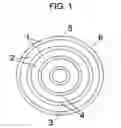
FIG. 1 is a top view of the new current collector plate.
FIG. 2 is a side view of the new current collector plate.
DETAILED DESCRIPTION OF THE INVENTION
Description of the Preferred Embodiment
Referring to FIG. 1, the preferred embodiment is a substantially planar circular plate of conductive material 6 (hereafter referred to as “current collector plate”) with alternating concentric ridges 1 and channels 2 on one side. Drilled perpendicular to the concentric ridges 1 and through the diameter of the current collector plate 6 is a series of holes 4 that serve to distribute fuel or oxidant across the proton exchange membrane of a fuel cell. The first in the series of holes 4 serves as the inlet 3 for fuel or oxidants. The last in the series of holes 4 on the opposite side of the current collector plate 6 serves as the outlet 5 for by-products.
Referring to FIG. 2, the current collector plate 6 is depicted on a side view showing the inlet 3 for fuel or oxidant.
Operation of the Preferred Embodiment
When in operation, two identical new current collector plates 6 are placed together with the alternating concentric ridges 1 and channels 2 facing each other and a proton exchange membrane in between. The two current collector plates 6 serve as the anode and cathode side of a typical proton exchange membrane fuel cell. As fuel or oxidant is introduced through the inlet 3 it follows the path of each concentric channel 2 thus being distributed substantially evenly across the proton exchange membrane. By-products exit through the outlet 5.
Description of a Second Embodiment
The second embodiment is identical to the first embodiment except that the material from which it is constructed is any non-conductive material. This material is then coated with an electrically conductive material to allow normal operation of the PEM fuel cell.
Conclusion and Scope
From the preceding description the reader will understand that the new current collector plate is structurally sound, easy to manufacture, and substantially simpler than the prior art. The preferred embodiment is a circular plate with concentric ridges and channels, however it will be immediately obvious to those skilled in the art that any concentric polygon shape could be used to obtain the same simple fuel distribution and structural integrity. Furthermore, more than one series of holes could be drilled through the diameter of the concentric ridges. These modifications and others will be apparent to those skilled in the art. Thus, the scope of the invention is not to be limited by the specification and is rather to be determined by the appended claims.
LIST OF REFERENCE NUMERALS
1.—Ridge of conductive material
2.—Fuel or oxidant channel
3.—Fuel or oxidant inlet
4.—Series of holes
5.—By-product outlet
6.—Conductive current collector plate
Claims
What is claimed is:1. A substantially planar conductive plate having alternating concentric ridges and channels extending away from one side and a series of holes through the diameter and perpendicular to said concentric ridges.
2. A substantially planar plate coated with a conductive material having alternating concentric ridges and channels extending away from one side and a series of holes through the diameter and perpendicular to said concentric ridges.
Images & Drawings included:


Sources:
- United States Patent and Trademark Office - verify current appl. status at the USPTO↗
Similar patent applications:
- » 20100112434
Cylindrical secondary battery having structure in which electrode assembly is connected with sealing cover via combination of current collector plate and current collector lead - » 20250087712
BIPOLAR PLATE AND CURRENT COLLECTOR PLATE OF FLOW BATTERY - » 20120177990
Electrode plate with a binder in a surface section with a lower glass transition point than a binder in a current collector plate section, secondary battery, and method for producing the electrode plate - » 20050186462
PEM fuel cell stack with floating current collector plates - » 20070003812
Current collector plates of bulk-solidifying amorphous alloys - » 20080079186
POLYMER ELECTROLYTE FUEL CELL HAVING IMPROVED CURRENT COLLECTOR PLATES AND METHOD OF FORMING THE SAME - » 20100216001
Rechargeable battery having current collector plate with protrusion - » 20060204825
Current collector plate for an electrochemical cell stack - » 20060115703
Fuel cell endplate comprising current collector plate and fuel cell incorporating same - » 20100233521
Rechargeable battery with current collector plate
Recent applications in this class:
- » 20250118773 2025-04-10
INTERNALLY MANIFOLDED INTERCONNECTS AND ELECTROCHEMICAL CELL COLUMN INCLUDING SAME - » 20250112251 2025-04-03
SYSTEMS AND METHODS FOR REDUCING DAMAGE ON A METAL PLATE STACK - » 20240387836 2024-11-21
SOLID OXIDE CELL STACK COMPRISING INTEGRATED INTERCONNECT, SPACER AND FIXTURE FOR A CONTACT ENABLING LAYER - » 20240339635 2024-10-10
Interconnector for a stack of solid oxide cells of the SOEC/SOFC type including different elements in relief - » 20240339634 2024-10-10
Device and Method for Electrically Contacting a Fuel Cell Assembly, and System Having the Device - » 20240282981 2024-08-22
STRUCTURE-INTEGRATED ELECTROCHEMICAL CELL AND STRUCTURE-INTEGRATED STACK CONSTRUCTED THEREFROM - » 20240234751 2024-07-11
CELL STACK AND CELL STACK ASSEMBLY - » 20240234750 2024-07-11
CONTACTING ASSEMBLY OF A BIPOLAR PLATE AND METHOD FOR CONTACTING A BIPOLAR PLATE - » 20240204214 2024-06-20
SEPARATOR FOR FUEL CELL - » 20240186538 2024-06-06
ELECTROCHEMICAL DEVICE