Suspension fastener
US20080118328A1
2008-05-22
11/602,803
2006-11-21
Abstract:
A suspension fastener has a bolt and a shaft. The bolt has a tip formed in a first end thereof and a revolving portion formed in a second end thereof. The shaft has a hole formed in a first end thereof and corresponding to the revolving portion. A shank is formed on a second end of the shaft and a recess is formed in a free end of the shank. A nut is fastened on the shank. The shaft extends through a furniture and is engaged with the bolt to suspend the furniture on the wall.
Interested in similar patents?
Get notified when new applications in this technology area are published.
Classification:
F16B5/0275 » CPC main
Joining sheets or plates, e.g. panels, to one another or to strips or bars parallel to them by means of fastening members using screw-thread the screw-threaded element having at least two axially separated threaded portions
A47B95/008 » CPC further
Fittings for furniture Suspension fittings for cabinets to be hung on walls
F16B39/00 IPC
Locking of screws, bolts or nuts
Description
BACKGROUND OF THE INVENTION
1. Field of the Invention
The present invention relates to a suspension fastener, and more particular to a suspension fastener for suspending furniture.
2. Description of the Related Art
Suspended furniture is used widely for decoration, and conventional fasteners are use to securely mount the suspended furniture on a wall.
However, the conventional fastener and the furniture are not integrity formed together thereby generating less aesthetics.
Therefore, the invention provides a suspension fastener to mitigate or obviate the aforementioned problems.
SUMMARY OF THE INVENTION
The main objective of the present invention is to provide a suspension fastener which can suspend a furniture with aesthetics.
Other objectives, advantages and novel features of the invention will become more apparent from the following detailed description when taken in conjunction with the accompanying drawings.
BRIEF DESCRIPTION OF THE DRAWINGS
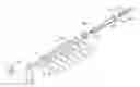
FIG. 1 is an exploded perspective view of a suspension fastener in according with the present invention;
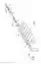
FIG. 2 is a side plane view in partial section of the suspension fastener in FIG. 1 with furniture; and
FIG. 3 is a perspective view of the suspension fastener in FIG. 1 with the furniture.
DETAILED DESCRIPTION OF THE PREFERRED EMBODIMENT
With reference to FIG. 1, a suspension fastener has a bolt (10), a shaft (20) and a nut (30).
The bolt (10) has a tip (11) formed in a first end thereof and a revolving portion (12) formed in a second end thereof. A free end of the revolving portion (12) has a cross groove (13). A thread (14) is formed around an outer surface of the bolt (10).
The shaft (20) has a threaded hole (21) formed in a first end thereof and corresponding to the thread (14). A shank (22) is formed on a second end of the shaft (20) and a recess (23) is formed in a free end of the shank (22). The recess (23) has a cross shape.
The nut (30) is screwed with the shank (22).
With reference to FIGS. 1 and 3, the tip (11) is inserted into a wall by rotating the revolving portion (12) with a tool so that the bolt (10) is fixed in the wall. The threaded hole (21) is screwed with the thread (14), and the shaft (20) extends through an orifice (51) in a furniture (50). Furthermore, the nut (30) is fastened to the shank (22). Hence, the furniture (50) is suspended on the wall with fasteners.
Additionally, the furniture (50) can be extended by the shaft (20) at first. The shank (22) is rotated with a tool engaging with the recess (23) so that the shaft (20) is screwed onto the bolt (10). Then, the nut (30) is coupled with the shank (22) whereby the furniture (50) can also be suspended on the wall.
Hence, the shaft (20) is mounted in the furniture (20) so that the appearance of the furniture is aesthetic.
It is to be understood, however, that even though numerous characteristics and advantages of the present invention have been set forth in the foregoing description, together with details of the structure and function of the invention, the disclosure is illustrative only. Changes may be made in details, especially in matters of shape, size, and arrangement of parts within the principles of the invention to the full extent indicated by the broad general meaning of the terms in which the appended claims are expressed.
Claims
What is claimed is:1. A suspension fastener comprising:
a bolt having
a tip formed in a first end thereof,
a revolving portion formed in a second end thereof;
a shaft having
a hole formed in a first end thereof and corresponding to the revolving portion; and
a nut engaged with a second end of the shaft.
2. The suspension fastener as claimed in claim 1, wherein a free end of the revolving portion has a groove and a thread is formed in an outer surface of the bolt, the shaft has a threaded hole formed in a first end thereof and corresponding to and screwed with the thread, a shank is formed on a second end of the shaft and a recess is formed in a free end of the shank.
3. The suspension fastener as claimed in claim 1, wherein the recess and the groove respectively have a cross shape.
Images & Drawings included:


Sources:
- United States Patent and Trademark Office - verify current appl. status at the USPTO↗
Similar patent applications:
- » 20200248736
OFF-ROAD VEHICLE SUSPENSION FASTENER - » 20120128406
Set for Fastening of Measuring Device, particularly Rangefinder, to Monitored Element of Building Construction, especially of the roof, Fastening Method of Measuring Device Using Such Set and Suspension for Fastening of Measuring Device - » 20110139551
Suspension-means end-fastener with fixing element - » 20110271619
WALL ATTACHMENT SYSTEM COMPRISED OF A WOOD FASTENER AND METHOD INVOLVING SUSPENSION - » 20240198846
HEAVY-DUTY VEHICLE BATTERY SUSPENSION SYSTEM COMPRISING A PYROTECHNICAL FASTENER - » 20090084636
End-connector and method for fastening a flat-belt type suspension means of an elevator system - » 20130232669
Fastener for low profile protective helmet internal suspension padding - » 20210283967
Air suspension strut having an elastic damper bearing fastening - » 20060060107
Assembly for fastening a transportation device of a cableway system on a suspension bar - » 20160376016
Suspension structure for suspending a turboprop having two unducted propellers from a structural element of an aircraft with rigid fastening of the air intake structure
Recent applications in this class:
- » 20210140455 2021-05-13
APPARATUS AND METHOD FOR ANCHORING FASTENERS - » 20200378419 2020-12-03
Double threaded standoff fastener - » 20200072264 2020-03-05
Materials and methods for joining metal sheets - » 20190293100 2019-09-26
Double-ended dual attached fastener - » 20180223885 2018-08-09
Coupling member, a method of fixing the coupling member to an object, and a display device having the coupling member - » 20180163757 2018-06-14
Dual-threaded screw structure - » 20170314594 2017-11-02
Double threaded standoff fastener - » 20160356295 2016-12-08
Fixing structure and fixing method - » 20160061240 2016-03-03
Coupling structure including stud bolt - » 20140301804 2014-10-09
Adjustable tower stud assembly