Method and system for multi-purposely controlling an internal-combustion engine on an engine bench testing unit
US20080120007A1
2008-05-22
11/579,599
2005-05-04
✅ Patent granted
US 7,920,954 B2
2011-04-05
WO; PCT/FR2005/001172; 20050504
WO; WO2005/116430; 20051208
Willis R. Wolfe, Jr. | Johnny H Hoang
2025-11-05
Abstract:
The present invention relates to a system and to a method for universal operation of an internal-combustion engine (2), comprising at least an actuator connected to a working device of the engine, an electronic card (3) comprising a programmable logic FPGA component and means (9, 10) for synchronizing the card according to the engine cycle. The method, generates, in the component, an angular reference point in the engine cycle for each cylinder; generates, through the component, actuator control pulses, the pulses being parameterizable in phase and in duration, independent and linked with a single cylinder, performing multiplexing of the pulses so as to distribute them over at least one of the physical outputs of the card specific to the cylinder considered; and controlling at least one of the actuators linked with one of the physical outputs of the card specific to the cylinder considered, by means of at least one of the control pulses.
Assignee:
- Institut Francais Du Petrole 40 🇫🇷 Cedex, France
Interested in similar patents?
Get notified when new applications in this technology area are published.
Classification:
F02D41/28 » CPC main
Electrical control of supply of combustible mixture or its constituents characterised by the use of digital means using computer, e.g. microprocessor Interface circuits
F01L9/20 » CPC further
Valve-gear or valve arrangements actuated non-mechanically by electric means
F02D41/249 » CPC further
Electrical control of supply of combustible mixture or its constituents characterised by the use of digital means using essentially read only memories; Particular ways of programming the data; Methods for rewriting Methods for preventing the loss of data
F02D41/266 » CPC further
Electrical control of supply of combustible mixture or its constituents characterised by the use of digital means using computer, e.g. microprocessor the computer being backed-up or assisted by another circuit, e.g. analogue
G01M15/04 » CPC further
Testing of engines Testing internal-combustion engines
F01L2800/00 » CPC further
Methods of operation using a variable valve timing mechanism
F01L2820/042 » CPC further
Details on specific features characterising valve gear arrangements; Sensors Crankshafts position
F02D41/009 » CPC further
Electrical control of supply of combustible mixture or its constituents using means for generating position or synchronisation signals
F02D41/00 IPC
Electrical control of combustion engines
F02D41/00 IPC
Electrical control of supply of combustible mixture or its constituents
Description
BACKROUND OF THE INVENTION
1. Field of the Invention
The present invention relates to a method and to an associated system comprising an electronic card hereinafter TIMER PCI allowing operation in a universal manner any type of internal-combustion engine, 2 or 4 stroke, gasoline (mono and multispark), diesel (mono and multi-injection), according to a distribution extended to up to four cylinders per card.
2. Description of the Prior Art
Operating an engine has been performed either using commercial computers used by the general public which are limited to a range of operation of an engine defined by the car manufacturer, or using specific R&D engine test bench control equipments used by car parts manufacturers to develop all the engine control strategies and whose use is limited to a make of car.
SUMMARY OF THE INVENTION
On the other hand, the system and the method according to the invention HAS the advantage of universal operation FOR any type of engine independently of the car manufacturer and/or the associated car parts manufacturer and providing an operation open to all the engine control strategy development perspectives based on the increasing power of PC compatible microcomputers.
The present invention relates to a method for operating an internal-combustion engine, comprising at least an actuator connected to a working device of the engine, an electronic card comprising a programmable logic component FPGA and means for synchronizing the card according to the engine cycle. The method, the following stages are carried out:
-
- generating, through the component, an angular reference point in the engine cycle for each cylinder;
- generating, through the component, actuator control pulses, the pulses being parameterizable in phase and in duration, independent and linked with a single cylinder;
- performing multiplexing of the pulses so as to distribute them over at least one of the physical outputs of the card specific to the cylinder considered;
- controlling at least one of the actuators linked with one of the physical outputs of the card specific to a cylinder, by means of at least one of the control pulses.
The pulses can be distributed in any order over one or more outputs.
Synchronization can be obtained from at least one of the following sensors:
-
- for a 2-stroke engine: an angular coder, a 58X vehicle target on the engine crankshaft;
- for a 4-stroke engine: a camshaft sensor and at least one angular coder, or a 58X vehicle target on the engine crankshaft.
The invention also relates to a system for operating an internal-combustion engine, comprising at least an actuator connected to a working device of the engine, an electronic card comprising a programmable logic component FPGA and means for synchronizing the card according to the engine cycle. In the system, the component comprises means programmed to:
-
- generate an angular reference point in the engine cycle for each cylinder;
- generate actuator control pulses, the pulses being parameterizable in phase and in duration, and being independent and linked with a cylinder;
- multiplex the pulses so as to distribute them over at least one of the physical outputs specific to a cylinder, and
- control at least one of the actuators linked with one of the physical outputs specific to the cylinder, by means of at least one of the control pulses.
The synchronization means can comprise:
-
- for a 2-stroke engine, at least one of the following sensors: an angular coder, a 58 X vehicle target on the engine crankshaft,
- for a 4-stroke engine, a camshaft sensor and at least one of the following sensors: an angular coder, a 58X vehicle target on the engine crankshaft.
The actuator can be: an injection nozzle, a spark plug, an electromagnetic valve control, or a LASER camera shot.
At least eight control pulses can be generated per cylinder.
There can be at least four physical outputs specific to each cylinder.
BRIEF DESCRIPTION OF THE DRAWINGS
Other features and advantages of the present invention will be clear from reading the description hereafter of an embodiment given by way of non limitative example, with reference to the accompanying figures wherein:
FIG. 1 diagrammatically shows the implementation of the invention;
FIG. 2 describes the structure and the organization of the implementation of the invention; and
FIG. 3 shows an example of signal generation.
DETAILED DESCRIPTION
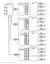
FIG. 1 shows an engine 2 operated by means of a PC type computer 1 comprising a TIMER PCI type electronic circuit board or card 3. The system is synchronized to the signals provided by an angular coding system 9. The coding system can be either an angular coder delivering “revolution signal” information and “angular signal” information of resolution equal to 1° CA, ½° CA, 1/50 CA or 1/10° CA, knowing that, in the figure, ° V=° CA=crank angle degree, or a 58X type vehicle target, i.e. having 60 teeth of 60 crank angle resolution (with 2 consecutive teeth missing) fastened to the crankshaft of engine 2. A second synchronization sensor 10 connected to the camshaft allows recognition of the revolution of the reference cylinder (usually cylinder No. 1) for a four-stroke engine whose combustion cycle equals two revolutions. Reference number 12 designates an angular coding signal conditioning and shaping block.
The TIMER PCI card has a standard format of the PCI bus of a PC compatible microcomputer. It generates the actuator control pulses (for example in FIG. 1: fuel injection nozzles 7, spark plugs 6) via dedicated power interfaces, for example a spark generator 4 through a multiconductor 13 or an injection power interface 11 through a multiconductor 8, themselves connected to the card by a multiconductor 5.
The TIMER PCI card comprises a FPGA (Field Programmable Gate Array) type programmable logic component, a component forming the interface with the PCI bus of the PC compatible microcomputer, circuits providing electrical isolation of the inputs/outputs and circuits providing the required supplies.
The FPGA component contains all the functionalities provided by the TIMER PCI board. They are described in VHDL language (Very High Speed Integrated Circuit “VHSIC” Hardware Description Language). The organization of these functionalities is the core of the present invention.
It allows generation of up to 8 control pulses per cylinder per engine cycle, for a diesel or gasoline 2 or 4 stroke engine up to 4 cylinders.
This architecture is based on taking into account 4 complex logic synchronization inputs coming, on the one hand, from an angular coding system of the engine crankshaft such as an angular coder or a 58X vehicle target and, on the other hand, from a camshaft sensor MC of any type.
It allows controlling 16 electrically isolated (mass decoupling) complex logic outputs for generation of the control pulses (4 outputs per cylinder). Each control pulse is parameterized for each engine cycle by phase and a duration. The phase is always expressed in crank angle degrees according to a selected angular precision (1° CA, ½° CA, ⅕° CA or 1/10 CA). The duration can be expressed in crank angle degrees according to a selected angular precision (1° CA, ½° CA, ⅕° CA or 1/10 CA) or to a selected time precision expressed in microseconds (μs).
Part of the invention pertains to the organization of the VHDL functionalities of the FPGA component of the TIMER PCI board. It allows operation in a universal manner any type of 2 or 4 stroke engine, gasoline or diesel, multi-injection or multi-spark, according to an arrangement ranging from 1 to 4 cylinders per TIMER PCI card. Several TIMER PCI cards can be associated to meet an arrangement with more than 4 cylinders.
The concept associates with each cylinder a specific reference called “Combustion top dead center PMH”, knowing that the working order of the cylinders of a 4-stroke engine is 1/3/4/2. The 8 control pulses (per channel or per cylinder) are phase and duration programmable in relation to their respective “combustion” top dead center PMH.
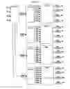
FIG. 2 shows a block diagram of the FPGA. The FPGA is divided up into four totally identical subassemblies (cylinder 1 to cylinder 4).
Each one of these block diagrams provides:
-
- generation (GEN-PMH) of a top dead center PMH specific to the cylinder considered (PMH1, PMH2, PMH3, PMH4), wherein:
- E1: input of the “angular signal” of the angular coder (1° CA, ½° CA, ⅕° CA or 1/100 CA);
- E2: input of the AAC signal of the camshaft sensor;
- E3: input of the “revolution signal” of the angular coder;
- E4: input of the signal of the 58X vehicle target (60-teeth ring with 2 consecutive teeth missing);
- generation (GEN1-4) of 8 independent pulses specifically linked with the cylinder considered, Fxy representing an internal signal characterized by the presence of a pulse defined by a phasing and a duration per engine cycle on the cylinder considered x, y from 1 to 8;
- multiplexing (MULT) of the 8 previous pulses in order to ensure distribution thereof over each of the 4 physical outputs, specifically linked with the cylinder, Sxz: output z (1-4) of a signal can be the combination of signals Fxy per engine cycle on cylinder x.
This distribution can be operated in a flexible way by programming and allows orientation of from 0 to 8 pulses, in any order, towards any one of the four physical outputs.
What is referred to as “pulse” is the elementary actuator control protocol. The pulse is a combination of two parameters: “phase” which designates the angular position at the start or at the end of the actuator control on the engine cycle considered, and “duration” which designates, from the “phase” above, the time when control of the actuator on the engine cycle considered is stopped.
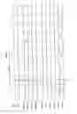
FIG. 3 shows an example of generation of a signal S11 which is a combination of signals F11, F12, F13 and F14 on reference frame PMH1 corresponding to cylinder 1. Reference frame PMH1 is made up from references E2 (MC) and E3 (revolution signal).
Two examples showing the flexibility of such an organization are described hereafter.
EXAMPLE 1
Operating a Conventional 4-Stroke Gasoline 4-Cylinder Engine
This engine is operated by controlling 4 ignition coils and 4 injection nozzles. Each one of these 8 actuators requires a logic output of the TIMER PCI card. Finally, each one of these 8 logic outputs must have an elementary control pulse characterized by its phase and duration parameterization.
Logical parameterization of the TIMER PCI card from the PC compatible microcomputer generates two pulses per cylinder and assigns each one of these two pulses to a distinct logic output. Thus, operating the engine considered can be performed without bringing any material change to the TIMER PCI board.
EXAMPLE 2
Operating a Multiple-Injection (8 Injections Per Engine Cycle) 4-Stroke Common Rail Diesel 4-Cylinder Engine
This engine is operated by controlling 4 injection nozzles. Each one of these four actuators requires a logic output of the TIMER PCI card. Finally, each one of these 4 logic outputs must have a set of 8 elementary control pulses defined by their phase and duration parameterization.
Logical parameterization of the TIMER PCI board from the PC compatible microcomputer thus generates 8 pulses per cylinder and assigns all of these eight pulses to a single logic output. Thus, operating the engine can be performed without bringing any material change to the TIMER PCI board.
Claims
1. A method for operating an internal-combustion engine, comprising at least one actuator connected to a working device of the engine, a circuit board comprising a programmable logic FPGA component and means for synchronizing the board according to the engine cycle, comprising:
generating, in the component, an angular reference point in the engine cycle for each cylinder;
generating, through the component, actuator control pulses, the pulses including phase and duration being independent and linked with a single cylinder;
performing multiplexing of the pulses to distribute the pulses over at least one of the physical outputs of the card specific to a cylinder considered; and
controlling at least one of the actuators linked with one of the physical outputs of the card specific to a cylinder, by means of at least one of the control pulses.
2. A method as claimed in claim 1, wherein the pulses are distributed in any order over one or more outputs.
3. A method as claimed in claim 1, wherein synchronization is obtained from at least one of the following sensors:
for a 2-stroke engine: an angular coder, a 58 X vehicle target on the engine crankshaft; and
for a 4-stroke engine: a camshaft sensor and at least: an angular coder, a 58X vehicle target on the engine crankshaft.
4. A system for operating an internal-combustion engine, comprising at least an actuator connected to a working device of the engine, a circuit board comprising a programmable logic FPGA component and means for synchronizing the card according to the engine cycle, wherein said component comprises means programmed to:
generate an angular reference point in the engine cycle for each cylinder;
generate actuator control pulses, the pulses including phase and duration, being independent and linked with a cylinder;
multiplex the pulses so as to distribute the pulses over at least one of the physical outputs specific to the cylinder; and
controlling at least one of the actuators linked with one of the physical outputs specific to the cylinder, by means of at least one of the control pulses.
5. A system as claimed in claim 4, wherein the synchronization means comprises:
for a 2-stroke engine, at least one of: an angular coder or a 58 X vehicle target on the engine crankshaft; and
for a 4-stroke engine, a camshaft sensor and at least one of: an angular coder or a 58X vehicle target on the engine crankshaft.
6. A system as claimed in claim 4, wherein the actuator is any one of: an injection nozzle, a spark plug, an electromagnetic valve control, and a LASER camera shot.
7. A system as claimed in claim 4, wherein at least eight control pulses are generated per cylinder.
8. A system as claimed in claim 4, wherein there are at least four physical outputs specific to each cylinder.
9. A system as claimed in claim 4, wherein the actuator is: an injection nozzle, a spark plug, an electromagnetic valve control, a LASER camera shot.
10. A method as claimed in claim 2, wherein synchronization is obtained from at least one of the following sensors:
for a 2-stroke engine: an angular coder, a 58 X vehicle target on the engine crankshaft; and
for a 4-stroke engine: a camshaft sensor and at least: an angular coder, a 58X vehicle target on the engine crankshaft.
11. A method for operating an internal-combustion engine, comprising at least one actuator connected to a working device of the engine, a circuit board comprising a programmable logic component and means for synchronizing the board according to the engine cycle, comprising:
generating, in the component, an angular reference point in the engine cycle for each cylinder;
generating, through the component, actuator control pulses, the pulses including phase and duration, being independent and linked with a single cylinder;
performing multiplexing of the pulses to distribute the pulses over at least one of the physical outputs of the component specific to a cylinder; and
controlling at least one of the actuators linked with one of the physical outputs of the component specific to the cylinder, by means of at least one of the control pulses.
12. A method as claimed in claim 11, wherein the pulses are distributed in any order over one or more outputs.
13. A method as claimed in claim 11, wherein synchronization is obtained from at least one of the following sensors:
for a 2-stroke engine: an angular coder, a 58 X vehicle target on the engine crankshaft; and
for a 4-stroke engine: a camshaft sensor and at least: an angular coder, a 58X vehicle target on the engine crankshaft.
14. A system for operating an internal-combustion engine, comprising at least an actuator connected to a working device of the engine, comprising a programmable logic component and means for synchronizing the component according to the engine cycle, wherein said component comprises means programmed to:
generate an angular reference point in the engine cycle for each cylinder;
generate actuator control pulses, the pulses including phase and duration, being independent and linked with a cylinder;
multiplex the pulses so as to distribute the pulses over at least one of the physical outputs specific to the cylinder; and
controlling at least one of the actuators linked with one of the physical outputs specific to the cylinder, by means of at least one of the control pulses.
15. A system as claimed in claim 14, wherein the synchronization means comprises:
for a 2-stroke engine, at least one of: an angular coder or a 58 X vehicle target on the engine crankshaft; and
for a 4-stroke engine, a camshaft sensor and at least one of: an angular coder or a 58X vehicle target on the engine crankshaft.
16. A system as claimed in claim 14, wherein the actuator is any one of: an injection nozzle, a spark plug, an electromagnetic valve control, and a LASER camera shot.
17. A system as claimed in claim 4, wherein at least eight control pulses are generated per cylinder.
18. A system as claimed in claim 4, wherein there are at least four physical outputs specific to each cylinder.
19. A system as claimed in claim 4, wherein the actuator is: an injection nozzle, a spark plug, an electromagnetic valve control, a LASER camera shot.
20. A method as claimed in claim 12, wherein synchronization is obtained from at least one of the following sensors:
for a 2-stroke engine: an angular coder, a 58 X vehicle target on the engine crankshaft; and
for a 4-stroke engine: a camshaft sensor and at least: an angular coder, a 58X vehicle target on the engine crankshaft.
Images & Drawings included:
Sources:
- United States Patent and Trademark Office - verify current appl. status at the USPTO↗
Recent applications in this class:
- » 20250059929 2025-02-20
INTERNAL COMBUSTION ENGINE AND METHOD FOR OPERATING AN INTERNAL COMBUSTION ENGINE - » 20220282683 2022-09-08
Apparatus and method for engine control - » 20220195958 2022-06-23
Method for determining a quantity of fuel injected into an internal combustion engine - » 20220099044 2022-03-31
Vehicle controller with complementary capacitance for analog-to-digital converter (A/D) low pass filter - » 20220065186 2022-03-03
Control logic circuit for connecting multiple high side loads in engine control module - » 20220056867 2022-02-24
Communication interface between an emission control system and internal combustion engine - » 20210340929 2021-11-04
Reluctor plate controller - » 20210254573 2021-08-19
Method for measuring a physical quantity by means of a digital sensor - » 20210215116 2021-07-15
System and method for determining the timing of an engine event - » 20210156330 2021-05-27
Control logic circuit for connecting multiple high side loads in engine control module
Recent applications for this Assignee:
- » 20100307831 2010-12-09
Well fluid comprising a fluorinated liquid phase - » 20100011958 2010-01-21
Method of deacidizing a gas with a fractional regeneration absorbent solution with control of the water content of the solution - » 20100010108 2010-01-14
Well cementing material - » 20100006067 2010-01-14
Method of controlling a spark-ignition supercharged internal-combustion engine, notably of gasoline type - » 20090311094 2009-12-17
Compact multiphase pump - » 20090272359 2009-11-05
Method of removing the fuel contained in the lubricating oil of an internal-combustion engine and engine using same - » 20090217660 2009-09-03
Feed circuit for supplying a supercharged engine with at least one fluid and method for supplying such an engine with at least one fluid - » 20090216423 2009-08-27
Fuel mixture autoignition control method, notably for diesel type internal-combustion engines, and engine using same - » 20090166043 2009-07-02
Riser pipe with rigid auxiliary lines - » 20090126462 2009-05-21
Method and device for evaluating flow parameters and electric parameters of porous medium