Display device
US20080142659A1
2008-06-19
11/946,845
2007-11-29
✅ Patent granted
US 7,946,548 B2
2011-05-24
-
-
Terrell Mckinnon | Steven M Marsh
2029-10-31
Abstract:
A display device includes a supporting member, a mounting plate, a fastener, and a monitor. The supporting member includes a base wall defining two through holes therein, and a clamping portion extending from a bottom portion thereof. The clamping portion is capable of contacting with an upper surface of the worktable. The mounting plate has two through holes defined therein configured for contacting with a lower surface of the worktable. The fastener extends through the through holes of the supporting member and the through holes of the mounting plate to sandwich the worktable. The monitor is provided with a pillar extending downward from a bottom portion thereof. The pillar of the monitor is attached to the supporting member.
Assignee:
- HON HAI PRECISION INDUSTRY CO., LTD. 12,833 🇹🇼 Tu-Cheng, Taiwan
- HON HAI PRECISION INDUSTRY CO., LTD. 2,724 🇹🇼 Tu-Cheng, New Taipei, Taiwan
Interested in similar patents?
Get notified when new applications in this technology area are published.
Classification:
F16M13/02 » CPC main
Other supports for positioning apparatus or articles ; Means for steadying hand-held apparatus or articles for supporting on, or attaching to, an object, e.g. tree, gate, window-frame, cycle
F16M11/24 » CPC further
Stands or trestles as supports for apparatus or articles placed thereon Stands for scientific apparatus such as gravitational force meters; Undercarriages with or without wheels changeable in height or length of legs, also for transport only, e.g. by means of tubes screwed into each other
F16M13/022 » CPC further
Other supports for positioning apparatus or articles ; Means for steadying hand-held apparatus or articles for supporting on, or attaching to, an object, e.g. tree, gate, window-frame, cycle repositionable
F16M2200/028 » CPC further
Details of stands or supports; Locking means for translational movement by positive interaction, e.g. male-female connections
Y10S248/917 » CPC further
Supports Video display screen support
Y10S248/919 » CPC further
Supports; Video display screen support Adjustably orientable video screen support
A47B96/06 IPC
Details of cabinets, racks or shelf units not covered by a single one of groups - ; General details of furniture Brackets or similar supporting means for cabinets, racks or shelves
E04G3/00 IPC
Scaffolds essentially supported by building constructions, e.g. adjustable in height
Description
BACKGROUND
1. Field of the Invention
The present invention relates to display devices, and more particularly to a flat panel display device.
2. Description of Related Art
Flat panel displays are more and more popularly used in offices. The relative lightness and compactness of flat panel displays (particularly in terms of front to back depth) make them particularly suitable for narrow workspaces. The characteristics of flat panel displays are particularly attractive in a small office/home office setting, because the relatively shallow front-to-back depth means that the display can be pushed back further from a user than would be possible with an equivalent cathode ray tube (CRT) monitor in many situations, taking up less precious desktop space in a user's work area.
Typically, a flat panel display includes a stand for supporting the flat panel display on the desk. The stand always takes up premium space on a desktop.
What is desired, therefore, is to provide a flat panel display which can economize workspace.
SUMMARY
In one embodiment, a display device includes a supporting member, a mounting plate, a fastener, and a monitor. The supporting member includes a base wall defining two through holes therein, and a clamping portion extending from a bottom portion thereof. The clamping portion is capable of contacting with an upper surface of the worktable. The mounting plate has two through holes defined therein configured for contacting with a lower surface of the worktable. The fastener extends through the through holes of the supporting member and the through holes of the mounting plate to sandwich the worktable. The monitor is provided with a pillar extending downward from a bottom portion thereof. The pillar of the monitor is attached to the supporting member.
Other advantages and novel features of the present invention will become more apparent from the following detailed description of preferred embodiment when taken in conjunction with the accompanying drawings, in which:
BRIEF DESCRIPTION OF THE DRAWINGS
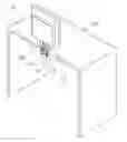
FIG. 1 is an assembled view of a display device in accordance with an embodiment, together with a worktable;
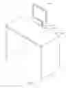
FIG. 2 shows another aspect view of FIG. 1;
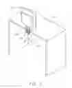
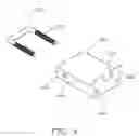
FIG. 3 is an exploded, isometric view of the display device of FIG. 1;
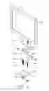
FIG. 4 is an enlarged view of parts of the display device of FIG. 3; and
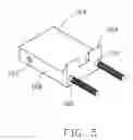
FIG. 5 is an assembled view of FIG. 4.
DETAILED DESCRIPTION
Referring to FIGS. 1 and 2, in an embodiment, a display device is mounted on a worktable 20.
Referring also to FIGS. 3 and 4, the display device includes a monitor 12, a supporting member 16, a mounting plate 14, two screws 171, a fastener 172, and two nuts 174. The monitor 12 has a pillar 122 extending downward from a bottom thereof. A plurality of aligned threaded mounting holes 124 are defined in opposite sides of the pillar 122 respectively. The supporting member 16 is generally a rectangular hollow rack with an entrance defined at one end thereof. The supporting member 16 includes a base wall 162, two first sidewalls 168 extending from two opposite sides of the base wall 162 respectively, a second sidewall 164 and a third sidewall 166 extending from the other opposite sides of the base wall 162. Two first through holes 167 are defined in the first sidewalls 168 respectively. Two second through holes 165 are defined in the base wall 162. An elongated cutout 169 is defined in an extending direction of the third sidewall 166. Two clamping portions 163 extend perpendicularly from a bottom portion of the second sidewall 164. The fastener 172 is U-shaped, and has two parallel arms 173. A plurality of screw threads is formed on two arms 173 of the fastener 172 respectively. Two through holes 142 are defined in a side portion of the mounting plate 14. The nuts 174 are generally gear-shaped. A screw hole 176 is defined in a center of each nut 174.
Referring also to FIG. 5, in assembly, the fastener 172 is placed in the supporting member 16 from the entrance of the supporting member 16. The free ends of the fastener 172 extend outward through the second through holes 165 of the base wall 162 respectively. Two clamping portions 163 of the supporting member 16 are placed on an upper surface of an edge portion of the worktable 20. The arms 173 of the fastener 172 are contiguous with a side of the edge portion of the worktable 20. The mounting plate 14 is placed on a lower surface of the flange of the worktable 20. The arms 173 of the fastener 172 extend through the through holes 142 of the mounting plate 14 respectively. The nuts 174 are screwed on the arms 173 of the fastener 172 respectively to press firmly the mounting plate 14 against the lower surface of the edge portion of the worktable 20. Thus the supporting member 16 is secured to the flange of the worktable 20. The pillar 122 of the monitor 12 is inserted into the supporting member 16 via the entrance of the supporting member 16. The screws 171 extend through the first through holes 167 of the supporting member 16 to screw into the mounting holes 124 respectively. Therefore, the monitor 12 is mounted to the supporting member 16. The cutout 169 of the supporting member 16 is used for viewing the state of the pillar 122 being inserted into the supporting member 16 for facilitating the screws 171 correctly extending into the mounting holes 124.
It can be understood, the fastener 172 may be two separate bolts. The mounting holes 124 are used for adjusting the height of the monitor 12 via the screws 172 extending through the first through holes 167 to screw in the different mounting holes 124 respectively.
It is to be understood, however, that even though numerous characteristics and advantages of the present invention have been set forth in the foregoing description, together with details of the structure and function of the invention, the disclosure is illustrative only, and changes may be made in detail, especially in matters of shape, size, and arrangement of parts within the principles of the invention to the full extent indicated by the broad general meaning of the terms in which the appended claims are expressed.
Claims
What is claimed is:1. A display device comprising:
a supporting member comprising a base wall defining two through holes therein, and a clamping portion extending from a bottom portion thereof, the clamping portion being capable of contacting with an upper surface of the worktable;
a mounting plate having two through holes defined therein configured for contacting with a lower surface of the worktable;
a fastener extending through the through holes of the supporting member and the through holes of the mounting plate to sandwich the worktable; and
a monitor provided with a pillar extending downward from a bottom portion thereof, the pillar of the monitor attached to the supporting member.
2. The display device as described in claim 1, further comprising a nut screwed onto the fastener to press firmly against the mounting plate on a lower surface of the worktable.
3. The display device as described in claim 2, wherein two through holes are defined in two opposite sides of the supporting member, a plurality of threaded mounting holes are defined in two opposite sides of the pillar of the monitor corresponding to the two through holes of the supporting member, two screws extend through the through holes to screw into the corresponding threaded mounting holes.
4. A display device comprising:
a supporting member for being placed on an upper surface of a worktable, two through holes defined in two opposite first sides of the supporting member, a cutout defined in a third side of the supporting member;
a mounting plate for being attached to an lower surface of the worktable;
a fastener connecting the supporting member with the mounting plate to sandwich the worktable; and
a monitor provided with a pillar extending downward from a bottom portion thereof, two threaded mounting holes defined in two opposite sides of the pillar of the monitor corresponding to the through holes of the supporting member, two screws extending through the through holes of the supporting member to screw into the corresponding threaded mounting holes of the pillar;
wherein the cutout of the supporting member is configured for viewing the state of the pillar being inserted into the supporting member for facilitating the screws correctly extending into the mounting holes.
5. The display device as described in claim 4, wherein the supporting member comprises a base wall, two first sidewalls extending from two opposite sides of the base wall, a second sidewall and a third sidewall extending from the other two opposite sides of the base wall.
6. The display device as described in claim 5, wherein the fastener is U-shaped and has two arms, two through holes are defined in the base wall for the arms of the fastener extending therethrough respectively.
7. The display device as described in claim 5, wherein two clamping portions extend from a bottom portion of the second sidewall for supporting the supporting member on an upper surface of a flange of the worktable.
8. The display device as described in claim 5, wherein the supporting member comprises an entrance defined in a top portion thereof for receiving the pillar of the monitor.
9. The display device as described in claim 8, wherein two first through holes are defined in the first sidewalls respectively for two screws extending therethrough to engage in the pillar of the monitor respectively.
10. The display device as described in claim 4, further comprising a nut screwed on the fastener to press firmly against the mounting plate on the lower surface of the side of the worktable.
Images & Drawings included:
Sources:
- United States Patent and Trademark Office - verify current appl. status at the USPTO↗
Similar patent applications:
- » 10740795
Display device conversion device, display device correction circuit, display device driving device, display device, display device examination device, and display method - » 20140092354
Display device substrate, display device substrate manufacturing method, display device, liquid crystal display device, liquid crystal display device manufacturing method and organic electroluminescent display device - » 20150340418
Display device substrate, display device substrate manufacturing method, display device, liquid crystal display device, liquid crystal display device manufacturing method and organic electroluminescent display device - » 20110199564
Display device substrate, display device substrate manufacturing method, display device, liquid crystal display device, liquid crystal display device manufacturing method and organic electroluminescent display device - » 20050236535
Device with stabilization leg, image display device, device mount block, device display system, image display device mount block, image display device display system, and image display device displaying method - » 20170132973
Display device, display device correction method, display device manufacturing method, and display device display method - » 20180047326
Display device, display device correction method, display device manufacturing method, and display device display method - » 20170132972
Display device, display device correction method, display device manufacturing method, and display device display method - » 20180122299
Display device, display device correction method, display device manufacturing method, and display device display method - » 20150270403
SEMICONDUCTOR DEVICE, DISPLAY DEVICE INCLUDING SEMICONDUCTOR DEVICE, DISPLAY MODULE INCLUDING DISPLAY DEVICE, AND ELECTRONIC DEVICE INCLUDING SEMICONDUCTOR DEVICE, DISPLAY DEVICE, AND DISPLAY MODULE
Recent applications in this class:
- » 20250290597 2025-09-18
WALL MOUNTED EQUIPMENT SUPPORT - » 20250290596 2025-09-18
FLOATING MOVING OBJECT AND PROBE MECHANISM - » 20250277558 2025-09-04
BRACKET, SYSTEM AND METHOD FOR HANGING ARTICLES UNDER A STRUCTURE - » 20250271099 2025-08-28
POULTRY FEEDER AND WATERER WITH HANDLE AND SUPPORT PROVIDING AN ADJUSTABLE HEIGHT - » 20250271098 2025-08-28
GRAB BAR ASSEMBLY - » 20250264188 2025-08-21
SEISMIC BRACING YIELD FUSE - » 20250264187 2025-08-21
STAND FOR DISPLAY APPARATUS AND DISPLAY APPARATUS INCLUDING SAME - » 20250243972 2025-07-31
SELF-INSERTING TREE HANGER - » 20250243971 2025-07-31
Mounting system for a tablet - » 20250243970 2025-07-31
RAIL SUPPORTING APPARATUS FOR SUPPORTING TUBULAR RAIL MEMBER FOR BOARDING SPORTS ON A BASE FRAME
Recent applications for this Assignee:
- » 20140233961 2014-08-21
Optical communication module including optical-electrical signal converters and optical signal generators - » 20140083669 2014-03-27
HEAT SINK - » 20140063746 2014-03-06
Electronic device with heat dissipation assembly - » 20140061224 2014-03-06
AUTOMATIC VENDING MACHINE - » 20140060914 2014-03-06
Enclosure with shield apparatus - » 20140058727 2014-02-27
MULTIMEDIA RECORDING SYSTEM AND METHOD - » 20140055955 2014-02-27
Fastener - » 20140055322 2014-02-27
DISPLAY SYSTEM AND HEAD-MOUNTED DISPLAY APPARATUS - » 20140054439 2014-02-27
CONTAINER DATA CENTER WITH SUPPORTING APPARATUS - » 20140054311 2014-02-27
AUTOMATIC VENDING MACHINE WITH MOVING MEMBER FOR PRODUCTS