Fan with spiral supercharging device
US20080152502A1
2008-06-26
11/613,358
2006-12-20
✅ Patent granted
US 7,564,684 B2
2009-07-21
-
-
Michael V Datskovskiy
2027-09-17
Abstract:
A fan with supercharging device has a hub and fan blades. A hub has a shape similar to a cone with a tip end and a circumferential side. The fan blades extend radially from the circumferential side of the hub. Each of the fan blades has a joining end being attached to the circumferential side, a free end extending outward the hub and a front edge and a rear edge being between the joining end and the free end respectively. The rear edge of the respective fan blade is shielded by the front edge of another fan blade next to it. The unshielded portion of the respective fan blade has an area gradually increases from the joining end to the free end. A projection is disposed at the free end along a direction of fluid flow. Hence, fluid pressure is capable of increasing significantly while the fan is in operation.
Assignee:
- ASIA VITAL COMPONENTS CO., LTD. 52 🇹🇼 Kaohsiung, Taiwan
Interested in similar patents?
Get notified when new applications in this technology area are published.
Classification:
F04D29/384 » CPC main
Details, component parts, or accessories; Rotors specially for elastic fluids for axial flow pumps; Blades characterised by form
F04D25/0613 » CPC further
Pumping installations or systems; Units comprising pumps and their driving means the pump being electrically driven the electric motor being specially adapted for integration in the pump the electric motor being of the inside-out type, i.e. the rotor is arranged radially outside a central stator
F04D29/164 » CPC further
Details, component parts, or accessories; Sealings between pressure and suction sides especially adapted for elastic fluid pumps of an axial flow wheel
F01D5/14 IPC
Blades; Blade-carrying members ; Heating, heat-insulating, cooling or antivibration means on the blades or the members; Blades Form or construction
F01D5/30 IPC
Blades; Blade-carrying members ; Heating, heat-insulating, cooling or antivibration means on the blades or the members Fixing blades to rotors; Blade roots ; Blade spacers
H05K7/20 IPC
Constructional details common to different types of electric apparatus Modifications to facilitate cooling, ventilating, or heating
H05K7/20 IPC
Constructional details common to different types of electric apparatus Modifications to facilitate cooling, ventilating, or heating
Description
BACKGROUND OF THE INVENTION
1. Field of the Invention
The present invention is related to a fan with spiral supercharging device and particularly to a device capable of increasing pressure of fluid outward the fan.
2. Brief Description of the Related Art
Referring to FIGS. 1 and 2, the conventional fan provides a hub 11 and a plurality of fan blades 12. The hub 11 is cylindrical with a flat facial end 111 having an area identical to the rear end thereof. The fan blades 12 surrounding the hub 11 each have a front edge 121 and a rear edge 122 with a gap 13 between every two adjacent fan blades 12, that is, the respective fan blade 12 is unshielded with another fan blade 12 next to it.
The problem of the preceding conventional fan is in that when the fan is in operation, the gap 13 becomes flow passage and fluid can pass outward through the gap 13. However, the fluid being acted by the fan blades 12 becomes less and it leads to pressure of the fluid moving outward being small. In addition, the fluid flows axially and diffuses outward immediately instead of gathering as a fluid beam moving outward.
SUMMARY OF THE INVENTION
In order to solve the preceding problem, an object of the present invention is to provide a fan with spiral supercharging device in which the fan blades overlap partly to each other and a projection is arranged at the free end of the respective fan blade along a direction of fluid flow for increasing fluid pressure and guiding fluid flowing toward the hub.
Another object of the present invention provides a fan with spiral supercharging device in which the hub has a shape similar to a cone with a tip end thereof disposed at the bottom of the fan facing a hot object and a circumferential side has a concave outward curved surface to guide fluid moving the center of the hot object.
Accordingly, a fan with spiral supercharging device according to the present invention has a hub and a plurality of fan blades. A hub has a shape similar to a cone with a tip end and a circumferential side. The fan blades extend radially from the circumferential side of the hub. Each of the fan blades has a joining end being attached to the circumferential side, a free end extending outward the hub and a front edge and a rear edge being between the joining end and the free end respectively. The rear edge of the respective fan blade is shielded by the front edge of another fan blade next to it. The unshielded portion of the respective fan blade has an area gradually increases from the joining end to the free end. A projection is disposed at the free end along a direction of fluid flow.
BRIEF DESCRIPTION OF THE DRAWINGS
The detail structure, the applied principle, the function and the effectiveness of the present invention can be more fully understood with reference to the following description and accompanying drawings, in which:
FIG. 1 is a perspective view of the conventional fan;
FIG. 2 is a sectional view of the conventional fan shown in FIG. 1;
FIG. 3 is a perspective view of a fan with spiral supercharging device according to the present invention;
FIG. 4 is a top view of the fan shown in FIG. 3;
FIG. 5 is a sectional view of the fan shown in FIG. 3; and
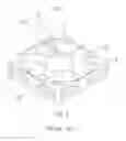
FIG. 6 is a sectional view illustrating the fan with a spiral supercharging device according to the present invention being attached to a heat sink.
DETAILED DESCRIPTION OF THE INVENTION
Referring to FIGS. 3 and 5, a fan with spiral supercharging device according to the present invention includes a hub 21 and a plurality of fan blades 22. The hub 21 has a shape similar to a cone with a central tip 211. The circumferential side 212 of the hub 21 is a concave outward curved surface.
Each of the fan blades 22 has a joining end 221 and a free end 222, a front edge 223 and a rear edge 224 as shown in FIG. 5. The joining end 221 is fixedly attached to the circumferential side 212 of the hub 21 and free end 222 extends outward the hub 21. The front edge 223 and the rear edge 224 are two radial sides of the respective fan blade 22. The rear edge 224 of each fan blade is shielded by the front edge 223 of another fan blade next to it and the unshielded part of the respective fan blade has a width increasing gradually from the joining end 221 to the free end 222. Hence, the respective fan blade 22 has a spiral shape.
A projection 225 is disposed at the free end 222 of the respective fan blade 22 to correspond to direction of the fluid flow and to be perpendicular to the main body of the respective fan blade 22. The hub 21 with the fan blades 22 movably fits with a base 231 in the fan frame 23.
When the hub 21 with the fan blades 22 rotates, fluid is driven to pass a space between every two fan blades 22. The unshielded area of the respective fan blade 22 is small near the joining end 221 such that fluid passes the small unshielded area subjects to small acting force and it results in less pressure while the unshielded area of the respective fan blade 22 near the free end 222 is large such that the fluid passes the large unshielded area subjects to large acting force and it results in more pressure. That is, small fluid pressure is close to the joining end 221 and large fluid pressure is close to the free end 222. The fluid with large pressure usually flows toward the fluid with small pressure such that the fluid passes the free end 222 moves toward the joining end 221. Under this circumference, the fluid flowing outward via the fan blades 22 is capable of congregating at the joining end 221 before leaving the fan blades 22 and preventing from diffusing outward.
Furthermore, the projection 225 at the free end of the respective fan blade 22 is capable of hitting the fluid near the free end 222 and allowing the fluid to change original flowing direction and move toward the joining end 221.
Referring to FIG. 6 in company with FIG. 3, the fan frame 23 is mounted to a hot object 24 in a way of the tip 211 of the hub 21 being next to the central position of the top of the heat sink 24. The hot object 24 can be a heat sink or a central processing unit (CPU). Once the hub 21 with the fan blades 22 is driven to rotate, fluid is induced by the fan blades 22 to enter the fan frame via the side having the base 231 and then flow outward via another side of the fan frame toward the heat sink 24. The fluid passing the fan blades 22 can gather at the joining end 221 of the respective fan blade 22 and moves along the circumferential side of the hub 21 to the tip end 211. Finally, the fluid flows to the center of the heat sink 24 to solve the problem of the center of the heat sink being a zone with highest heat for enhancing efficiency of heat dissipation.
While the invention has been described with referencing to a preferred embodiment thereof, it is to be understood that modifications or variations may be easily made without departing from the spirit of this invention, which is defined by the appended claims.
Claims
What is claimed is:1. A fan with spiral supercharging device comprising:
a hub having a shape similar to a cone with a tip end and a circumferential side; and
a plurality of fan blades extending radially from the circumferential side of the hub;
wherein each of the fan blades has a joining end being attached to the circumferential side and a free end extending outward the hub and a front edge and a rear edge being between the joining end and the free end; the rear edge of the respective fan blade is shielded by the front edge of another fan blade next to it; and unshielded portion of the respective fan blade has an area gradually increases from the joining end to the free end.
2. The fan with spiral supercharging device as defined in claim 1, wherein the hub is disposed in a fan frame.
3. The fan with spiral supercharging device as defined in claim 1, wherein the free end has a projection disposed along a direction of fluid flow.
4. The fan with spiral supercharging device as defined in claim 3, wherein the projection is perpendicular to the corresponding fan blade.
5. The fan with spiral supercharging device as defined in claim 1, wherein the tip end of the hub next to a center of a heat sink.
6. The fan with spiral supercharging device as defined in claim 1, wherein the tip end of the hub next to a center of a central processing unit (CPU).
7. The fan with spiral supercharging device as defined in claim 1, the circumferential side of the hub has a concave outward curved surface.
Images & Drawings included:


Sources:
- United States Patent and Trademark Office - verify current appl. status at the USPTO↗
Recent applications in this class:
- » 20250283481 2025-09-11
AEROELASTIC FAN BLADE - » 20250264113 2025-08-21
THERMAL STRATIFICATION MIXER FOR AN AIR HANDLING UNIT - » 20250250987 2025-08-07
IMPELLER FOR A DUCT - » 20250243873 2025-07-31
FAN BLADE, FAN AND FAN LAMP - » 20250198423 2025-06-19
IMPELLER, FAN, AND AIR-CONDITIONING APPARATUS - » 20250198422 2025-06-19
AXIAL FAN ASSEMBLY INCLUDING AN INTERMEDIATE SHROUD - » 20250198421 2025-06-19
FAN BLADE STRUCTURE - » 20250188947 2025-06-12
Stepped Leading Edge Fan Blade - » 20250172158 2025-05-29
BLADE FOR AN INDUSTRIAL AXIAL FAN WITH TIP LIFT APPENDAGE - » 20250067277 2025-02-27
INDUSTRIAL AXIAL FAN BLADE
Recent applications for this Assignee:
- » 20110186268 2011-08-04
FLAT TYPE HEAT PIPE DEVICE - » 20100038060 2010-02-18
HEAT DISSIPATION DEVICE CAPABLE OF COLLECTING AIR - » 20100027219 2010-02-04
FAN FRAME ASSEMBLY FOR A HEAT SINK - » 20090255658 2009-10-15
HEAT DISSIPATION MODULE - » 20090218082 2009-09-03
HEAT DISSIPATION MODULE - » 20090218073 2009-09-03
COOLING FIN - » 20090175045 2009-07-09
Heat dissipating structure for light emitting diodes - » 20090116196 2009-05-07
Water cooled heat dissipation module for electronic device - » 20090114375 2009-05-07
Water cooling type heat dissipation module for electronic device - » 20090028475 2009-01-29
Fan with an anti-leakage device for an oily bearing