HEAT DISSIPATION MODULE
US20090218082A1
2009-09-03
12/039,313
2008-02-28
Abstract:
A heat dissipation module includes a plurality of cooling fins and at least a guide heat pipe. The cooling fins stack to one another with at least a through hole at the respective cooling fin for being penetrated with the guide heat pipe. A projecting annular part is disposed at a side of the respective cooling fin to surround the circumference of the through hole with an indented spot at the periphery of the projecting annular part. The outer side of said guide heat pipe has an elongated recess extending along the length thereof to correspond to the indented spot such that the indented spot is capable of fitting with the recess after the guide heat pipe passing through the through hole respectively to facilitate the subsequent welding job.
Assignee:
- ASIA VITAL COMPONENTS CO., LTD. 49 🇹🇼 Kaohsiung, Taiwan
Interested in similar patents?
Get notified when new applications in this technology area are published.
Classification:
F28F1/32 » CPC main
Tubular elements; Assemblies of tubular elements; Tubular elements and assemblies thereof with means for increasing heat-transfer area, e.g. with fins, with projections, with recesses the means being only outside the tubular element and extending transversely the means having portions engaging further tubular elements
F28D15/0266 » CPC further
Heat-exchange apparatus with the intermediate heat-transfer medium in closed tubes passing into or through the conduit walls ; Heat-exchange apparatus employing intermediate heat-transfer medium or bodies in which the medium condenses and evaporates, e.g. heat pipes with separate evaporating and condensing chambers connected by at least one conduit; Loop-type heat pipes; with multiple or common evaporating or condensing chambers
H01L23/427 » CPC further
Details of semiconductor or other solid state devices; Arrangements for cooling, heating, ventilating or temperature compensation ; Temperature sensing arrangements; Fillings or auxiliary members in containers or encapsulations selected or arranged to facilitate heating or cooling Cooling by change of state, e.g. use of heat pipes
H01L23/467 » CPC further
Details of semiconductor or other solid state devices; Arrangements for cooling, heating, ventilating or temperature compensation ; Temperature sensing arrangements involving the transfer of heat by flowing fluids by flowing gases, e.g. air
H01L23/3672 » CPC further
Details of semiconductor or other solid state devices; Arrangements for cooling, heating, ventilating or temperature compensation ; Temperature sensing arrangements; Selection of materials, or shaping, to facilitate cooling or heating, e.g. heatsinks; Cooling facilitated by shape of device Foil-like cooling fins or heat sinks
H01L2924/0002 » CPC further
Indexing scheme for arrangements or methods for connecting or disconnecting semiconductor or solid-state bodies as covered by; Technical content checked by a classifier Not covered by any one of groups , and
H01L2924/00 » CPC further
Indexing scheme for arrangements or methods for connecting or disconnecting semiconductor or solid-state bodies as covered by
F28F3/02 IPC
Plate-like or laminated elements; Assemblies of plate-like or laminated elements Elements or assemblies thereof with means for increasing heat-transfer area, e.g. with fins, with recesses, with corrugations
Description
BACKGROUND OF THE INVENTION
1. Field of the Invention
The present invention is related to a structure of heat dissipation, and particularly to an improvement on a heat dissipation module for facilitating the assembly job and promoting the production efficiency significantly.
2. Brief Description of the Related Art
The processing speed of the electronic chip increases due to incessantly progress of technology but it leads to increase of the generated heat as well. Nevertheless, the high temperature is a primary reason of the undesirable operation efficiency and burn-out of the chip. Therefore, how to dissipate the heat from the chip for protecting the chip is one of the subjects that are researched and developed currently. In order to obtain the best effect, a plurality of cooling fins being stacked as a cooling fin set in association with the heat guide pipes are utilized in the most researches and developments for promoting the cooling efficiency.
Taiwan Patent Publication No. 449514 entitled “A METHOD FOR JOINING A GUIDE HEAT PIPE TO COOLING FINS” discloses a method that a soldering layer is coated on a joining surface between the guide heat pipe and the cooling fins and the joined guide heat pipe and the cooling fins heat up in a vacuum heating stove such that the solder tin can melt in the process of heating and form the phenomenon of capillary to permeate the joining surface for engagement tightly. Further, Taiwan Patent publication No. 1236337 entitled “A METHOD FOR FORMING A HEAT PIPE AND COOLING FINS discloses (a) a metal conductive medium layer is plated at a spot of the heat pipe and the cooling fins for joining the cooling fins; (b) the cooling fins are placed at the spot plated with the metal conductive medium; and (c) The conductive medium is heated up to melt between the heat pipe and the cooling fins and then cools down.
Although either the solder tin or the metal conductive medium of the preceding cited references is heated up for joining the heat pipe to the cooling fins, the heat pipe is circular in cross section and the cooling fins are easy to swing or rotate with respect to the heat pipe before the heat pipe is fixed to the cooling fins. That is, the heat pipe is unable to be located well during being joined to the cooling fins and it is easy to result in clearances between the heat pipe and the cooling fins to degrade the effect of heat transfer.
SUMMARY OF THE INVENTION
In order to overcome the deficiencies of the prior art, an object of the present invention is to provide a heat dissipation module, which is assembled easily for promoting production efficiency.
Accordingly, a heat dissipation module according to the present invention includes a plurality of cooling fins and at least a guide heat pipe. The cooling fins stack to one another with at least a through hole at the respective cooling fin for being penetrated with the guide heat pipe. A projecting annular part is disposed at a side of the respective cooling fin to surround the circumference of the through hole with an indented spot at the periphery of the projecting annular part. The outer side of said guide heat pipe has an elongated recess extending along the length thereof to correspond to the indented spot such that the indented spot is capable of fitting with the recess after the guide heat pipe passing through the through hole respectively to facilitate the subsequent welding job.
Wherein, the protrusion part can be circular or the square shape. Further, a plurality of the protrusion parts can be arranged irregularly on the plate member such that the effect of different eddy currents at the periphery of the cooling fin can be produced advantageously and the slots at the lateral sides of the respective protrusion part are helpful for increasing the coefficient of heat exchange of the cooling fin and enhancing the integral performance of the cooling fin.
BRIEF DESCRIPTION OF THE DRAWINGS
The detail structure, the applied principle, the function and the effectiveness of the present invention can be more fully understood with reference to the following description and accompanying drawings, in which:
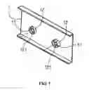
FIG. 1 is a perspective view of a cooling fin in a heat dissipation module according to a preferred embodiment of the present invention;
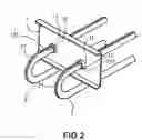
FIG. 2 is a perspective view illustrating the cooling fin shown in FIG. 1 being penetrated by two guide heat pipes;
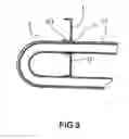
FIG. 3 is a sectional view of FIG. 2; and
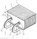
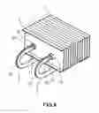
FIG. 4 is a perspective view of a heat dissipation module according to the present invention in which a plurality of the cooling fins stacking to each other and being penetrated by the heat guide pipes.
DETAILED DESCRIPTION OF THE INVENTION
Referring to FIGS. 1 to 4, a heat dissipation module according to a preferred embodiment of the present invention includes a plurality of cooling fins 1 and at least a guide heat pipe 2. The cooling fins 1 are stacked to one another. Each cooling fin 1 has at least a circular through hole 11 corresponding to the guide heat pipe 2. A side of the respective cooling fin 1 provides a projecting annular part 12 to surround the circumference of the through hole 11. The projecting annular part 12 has an indented spot 121 at the periphery thereof. The guide heat pipe 2 provides an elongated recess 21, which is formed continuously or discretely, extending along the length of the guide heat pipe 2 corresponding to the indented spot 121 such that the indented spot 121 can fit with the recess 21.
As the foregoing, the guide heat pipe 2 penetrates the through hole 11 of the respective stacked cooling fin in a way of the elongated recess 21 fitting with the indented spot 121 of the respective annular part 12 such that it facilitates the subsequent welding job for joining the guide heat pipe 2 to the respective cooling fin 1 firmly.
It is appreciated that the heat dissipation module according to the present invention is composed of a plurality of stacked cooling fins 1 and at least a guide heat pipe 2 with an projecting annular ring 12, which surrounds an end of at lest a through hole 11 of the respective cooling fin 1, having an indented spot 121 fitting with an elongated recess 21 of the guide heat pipe 2 to facilitate the subsequent welding job for joining the guide heat pipe 2 to the cooling fins firmly.
While the invention has been described with referencing to the preferred embodiment thereof, it is to be understood that modifications or variations may be easily made without departing from the spirit of this invention, which is defined by the appended claims.
Claims
What is claimed is:1. A heat dissipation module comprising:
a plurality of cooling fins stacking to one another with at least a through hole at the respective cooling fin to align to each other; and
at least a guide heat pipe penetrating said through hole;
wherein, a projecting annular part is disposed at a side of the respective cooling fin to surround the circumference of said through hole with an indented spot at the periphery of said projecting annular part; and the outer side of said guide heat pipe has an elongated recess extending along the length of said guide heat pipe to correspond to said indented spot such that said indented spot is capable of fitting with said recess after said guide heat pipe passing through said through hole respectively.
2. The heat dissipation module as defined in claim 1, wherein said recess has a shape to accommodate said indented spot.
3. The heat dissipation module as defined in claim 1, wherein said recess extends continuously or discretely.
Images & Drawings included:
Sources:
- United States Patent and Trademark Office - verify current appl. status at the USPTO↗
Similar patent applications:
- » 20170105312
Heat dissipating module, heat dissipating system and circuit module - » 20200170143
Heat dissipation module manufacturing method, heat dissipation module and electronic device - » 20170034952
FIXTURE DEVICE FOR HEAT-DISSIPATING MODULE AND HEAT-DISSIPATING MODULE HAVING FIXTURE DEVICE - » 20080055853
HEAT DISSIPATING MODULE AND ASSEMBLY OF THE HEAT DISSIPATING MODULE AND A COMPUTER HOUSING - » 20190154949
Heat dissipation module and system camera including heat dissipation module - » 20140092602
Heat dissipation module and modular lighting device with heat dissipation module - » 20120327605
Heat-dissipating module and assembled structure of heat-dissipating module and integrated circuit chipset - » 20110155361
Heat dissipation module and portable device having the heat dissipation module - » 20130248161
HEAT DISSIPATION MODULE AND METHOD OF USING THE HEAT DISSIPATION MODULE - » 20090180256
Heat-dissipating module having a dust removing mechanism, and assembly of an electronic device and the heat-dissipating module
Recent applications in this class:
- » 20250172350 2025-05-29
HEAT EXCHANGER - » 20250146766 2025-05-08
HEAT EXCHANGER - » 20250067524 2025-02-27
EVAPORATION APPARATUS INCLUDING ANGLE LIMITING PLATE - » 20250052520 2025-02-13
MICROCHANNEL HEAT EXCHANGER GROUP AND AIR CONDITIONING SYSTEM HAVING SAME - » 20250027727 2025-01-23
HEAT EXCHANGE PROMOTION MEMBER AND HEAT EXCHANGER - » 20240271882 2024-08-15
HEAT EXCHANGER - » 20240255232 2024-08-01
Heat Exchanger - » 20240255231 2024-08-01
HEAT EXCHANGER - » 20240210123 2024-06-27
HEAT EXCHANGER - » 20240200886 2024-06-20
Heat Exchanger
Recent applications for this Assignee:
- » 20110186268 2011-08-04
FLAT TYPE HEAT PIPE DEVICE - » 20100038060 2010-02-18
HEAT DISSIPATION DEVICE CAPABLE OF COLLECTING AIR - » 20100027219 2010-02-04
FAN FRAME ASSEMBLY FOR A HEAT SINK - » 20090255658 2009-10-15
HEAT DISSIPATION MODULE - » 20090218073 2009-09-03
COOLING FIN - » 20090175045 2009-07-09
Heat dissipating structure for light emitting diodes - » 20090116196 2009-05-07
Water cooled heat dissipation module for electronic device - » 20090114375 2009-05-07
Water cooling type heat dissipation module for electronic device - » 20090028475 2009-01-29
Fan with an anti-leakage device for an oily bearing - » 20090025912 2009-01-29
Heat dissipation apparatus with coarse surface capable of intensifying heat transfer