Feature protection for stereo lithographic manufacturing processes
US20080175424A1
2008-07-24
11/625,371
2007-01-22
✅ Patent granted
US 8,077,894 B2
2011-12-13
-
-
Huyen D Le
2030-10-14
Abstract:
To prevent stereo lithography (SLA) support structures for parts fabricated in an SLA apparatus from interfering with features in the parts, a structural shield such as a dome may be place around the feature and then discarded at the conclusion of the SLA process.
Inventors:
- Oleg Saltykov 25 🇺🇸 Fairlawn, NJ, United States
- Salman Parsi 7 🇺🇸 Somerset, NJ, United States
- Fred McBagonluri 2 🇺🇸 Windsor, NJ, United States
Assignee:
- SIEMENS HEARING INSTRUMENTS, INC. 50 🇺🇸 Piscataway, NJ, United States
Interested in similar patents?
Get notified when new applications in this technology area are published.
Classification:
H04R25/00 IPC
Deaf-aid sets, i.e. electro-acoustic or electro-mechanical hearing aids; Electric tinnitus maskers providing an auditory perception
H04R31/006 » CPC main
Apparatus or processes specially adapted for the manufacture of transducers or diaphragms therefor Interconnection of transducer parts
B29C64/124 » CPC further
Additive manufacturing, i.e. manufacturing of three-dimensional [3D] objects by additive deposition, additive agglomeration or additive layering, e.g. by 3D printing, stereolithography or selective laser sintering; Processes of additive manufacturing using only liquids or viscous materials, e.g. depositing a continuous bead of viscous material using layers of liquid which are selectively solidified
B29C64/40 » CPC further
Additive manufacturing, i.e. manufacturing of three-dimensional [3D] objects by additive deposition, additive agglomeration or additive layering, e.g. by 3D printing, stereolithography or selective laser sintering Structures for supporting 3D objects during manufacture and intended to be sacrificed after completion thereof
B29C70/30 » CPC further
Shaping composites, i.e. plastics material comprising reinforcements, fillers or preformed parts, e.g. inserts comprising reinforcements only, e.g. self-reinforcing plastics; Shaping operations therefor Shaping by lay-up, i.e. applying fibres, tape or broadsheet on a mould, former or core; Shaping by spray-up, i.e. spraying of fibres on a mould, former or core
B33Y10/00 » CPC further
Processes of additive manufacturing
H04R25/652 » CPC further
Deaf-aid sets, i.e. electro-acoustic or electro-mechanical hearing aids; Electric tinnitus maskers providing an auditory perception; Housing parts, e.g. shells, tips or moulds, or their manufacture Ear tips; Ear moulds
H04R25/658 » CPC further
Deaf-aid sets, i.e. electro-acoustic or electro-mechanical hearing aids; Electric tinnitus maskers providing an auditory perception; Housing parts, e.g. shells, tips or moulds, or their manufacture Manufacture of housing parts
B29L2031/7532 » CPC further
Other particular articles; Medical equipment; Accessories therefor Artificial members, protheses
B33Y40/00 » CPC further
Auxiliary operations or equipment, e.g. for material handling
B33Y80/00 » CPC further
Products made by additive manufacturing
H04R2225/77 » CPC further
Details of deaf aids covered by , not provided for in any of its subgroups Design aspects, e.g. CAD, of hearing aid tips, moulds or housings
Description
BACKGROUND AND SUMMARY OF THE INVENTION
A hearing instrument for insertion into the user's ear canal may be manufactured by fabricating the hearing instrument shell using stereo lithography (SLA), one of the processes mentioned in U.S. Patent Application Publication No. 2002/0196954 A1, published Dec. 26, 2002 and titled, “Modeling and fabrication of three-dimensional irregular surfaces for hearing instruments,” incorporated here by reference. When using SLA, a part is constructed layer by layer. Since the raw material is a liquid bath, a means of supporting the initial layers is required to prevent the piece from floating away.
Typically, a support structure is created along with the part and then later discarded (e.g., during a finishing process such as tumbling). One such support structure comprises a plurality of thin columns, perhaps braced together. When the part is finished, it is lifted out of the structure and the bath, and the support structure is discarded.
Some hearing instrument shells have receiver holes with finely detailed features. Since the receiver hole is located on the tip of the shell, it is one of the first items formed during the SLA process. Further, as the support structures are created simultaneously with the shell, these structures may extend into openings on the bottom of the shell, such as the receiver hole. Once the part is finished, extensive machining may be required to remove the support from the receiver hole and restore the hole structure.
The entry of the support structure into the receiver hole can be prevented by shielding the receiver hole with a structure such as a dome having a thin shell. Once the part is completed, the dome can be removed without harming the part.
BRIEF DESCRIPTION OF THE DRAWINGS
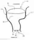
FIG. 1 is an elevation view of a hearing instrument in an ear canal and comprising a tip having a receiver hole and a vent hole;
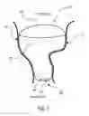
FIGS. 2 and 3 are perspective views of the tip of the hearing instrument shell, illustrating the receiver hole and the vent hole;
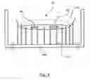
FIG. 4 is a drawing of the tip of the hearing instrument shell as it is fabricated and the accompanying support structures;
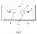
FIG. 5 is a partial cross-sectional view of the tip of the hearing instrument shell, illustrating a protective dome covering the receiver hole;
FIG. 6 is a drawing of the shell tip, having a protective dome covering the receiver hole, as it is fabricated, with the accompanying support structures not shown; and
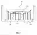
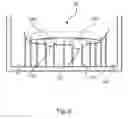
FIGS. 7 and 8 are drawings of the shell tip, having a protective dome, as it is fabricated and the accompanying support structures.
DESCRIPTION OF THE INVENTION
A hearing instrument 10 comprising a shell 20 and a faceplate 30 is shown in the user's ear canal 12 in FIG. 1. The shell 20 has a shell tip 40 comprising a receiver hole 42 and an optional vent hole 44. The receiver hole 42 and the optional vent hole 44 are shown again in perspective views of the hearing instrument shell tip 40 in FIGS. 2 and 3. Although the shell tip 40 is shown with a flat surface in FIGS. 2 and 3 (and in the subsequent figures), it may be rounded or assume some other shape.
An apparatus 100 for fabricating the hearing instrument shell 20 using stereo lithography (SLA) is shown in schematic representation in FIG. 4 with a portion of the shell tip 40. The figure also shows support structure elements 110. Although these support structure elements 110 are illustrated as thin, rectangular columns in the figure, they may assume the shape determined by the particular SLA process employed.
Since the support structure elements 110 are designed to extend to a solid surface, they will enter openings in the underside of the device being fabricated. For example, in FIG. 4, they extend into the receiver hole 42 and the vent hole 44. After the part has been completed, the portions of the support structure elements 110 remaining in the receiver hole 42 and the vent hole 44 must be removed. Further, if the receiver hole 42 has a shape other than a simple round hole, the hole must be restored to the desired configuration. For example, the receiver hole may have a keyway slot that has been obscured or otherwise altered by a support structure element 110. A machining operation may be required to restore that feature.
To prevent the intrusion of a support structure element 110 into the receiver hole 42 (or the vent hole 44), a protective structural shield may be built around or in front of the hole 42, 44. One such structure is a dome 120 with a thin shell, as shown in the cross-sectional view of the hearing instrument shell tip 40 in FIG. 5 and again in FIG. 6. The dome 120 has a drain hole 122 that permits excess material, in liquid form, to drain from the dome 120 when the completed part is removed from the SLA apparatus 100. Although the figures show a dome-shaped structure covering the receiver hole 42, other shapes could be used as well.
The thickness of the dome 120 is selected to facilitate its removal from the hearing instrument shell 20 during the finishing phase. For example, where the hearing instrument shell 20 has a thickness of 0.6-1.0 mm, the dome 120 may have a thickness of 0.1-0.2 mm.
In FIG. 7, the SLA apparatus 100 is again shown with a hearing instrument shell tip 40 having a dome 120 covering the receiver hole 42. As illustrated, the dome 120 prevents the support structure elements 110 from entering the receiver hole 42. In FIG. 8, an additional dome 130 covers the optional vent hole 44, similarly preventing the support structure elements 110 from entering the hole 44.
After the hearing instrument shell 20 is completed, it will undergo a finishing process such as tumbling. During that process, the domes 120, 130 and any support structure elements 110 that remain are removed.
Claims
What is claimed is:1. A method for fabricating a hearing instrument shell comprising at least one aperture, using stereo lithography, comprising:
generating a model of the shell for a stereo lithography fabrication apparatus;
determining the location of at least one aperture in the model of the shell;
selectively adding, a structural shield covering the aperture;
providing the model to the stereo lithography fabrication apparatus;
fabricating the shell with the stereo lithography fabrication apparatus; and
removing the structural shield.
2. A method as set forth in claim 1, where selectively adding a structural shield covering the aperture comprises adding a dome.
3. A method as set forth in claim 1, where selectively adding a structural shield covering the aperture comprises covering a receiver hole.
4. A method as set forth in claim 1, where selectively adding a structural shield covering the aperture comprises covering a vent hole.
5. An apparatus for protecting a feature of a shell fabricated in a stereo lithography fabrication apparatus comprising a structure surrounding the feature.
6. An apparatus as set forth in claim 5, where the structure surrounding the feature comprises a dome.
Images & Drawings included:


Sources:
- United States Patent and Trademark Office - verify current appl. status at the USPTO↗
Recent applications in this class:
- » 20250287166 2025-09-11
METHOD OF ASSEMBLING A LOUDSPEAKER AND VOICE COIL FORMER FOR USE THEREIN - » 20250133360 2025-04-24
RIBBON SPEAKER - » 20250030998 2025-01-23
FOUNDRY-COMPATIBLE PROCESS FOR INTEGRATED MICRO-SPEAKER AND MICROPHONE - » 20240284131 2024-08-22
METHOD FOR MANUFACTURING MEMS ACOUSTIC SENSOR - » 20230239641 2023-07-27
METHOD OF MAKING MEMS MICROPHONE WITH AN ANCHOR - » 20230164505 2023-05-25
METHOD FOR MANUFACTURING LOUDSPEAKER HAVING WIRE DAMPER WITH LOCALLY ADJUSTABLE ELASTICITY - » 20230051272 2023-02-16
ELECTRO-ACOUSTIC TRANSDUCER INCLUDING A MINIATURE VOICE COIL - » 20220408208 2022-12-22
Method of manufacturing acoustic devices with improved sensitivity - » 20220377480 2022-11-24
Bone conduction microphone - » 20220174441 2022-06-02
LOUDSPEAKER HAVING WIRE DAMPER WITH LOCALLY ADJUSTABLE ELASTICITY AND METHOD FOR MANUFACTURING THE SAME
Recent applications for this Assignee:
- » 20120008808 2012-01-12
Hearing aid with occlusion reduction - » 20110289764 2011-12-01
Method of Assembling A Hearing Aid - » 20100290656 2010-11-18
Domes for a receiver-in-the-canal hearing instrument - » 20100286964 2010-11-11
Method of generating an optimized venting channel in a hearing instrument - » 20100226517 2010-09-09
Behind-the-ear accessory module for a helix hearing instrument - » 20100226502 2010-09-09
Method For Fabricating A Hearing Device - » 20100131090 2010-05-27
METHOD AND PROCESS FOR AUTOMATING THE DESIGN OF A LOCKING MECHANISM FOR A HEARING INSTRUMENT - » 20100094446 2010-04-15
Feature driven rule-based framework for automation of modeling workflows in digital manufacturing - » 20100092001 2010-04-15
Test coupler for hearing instruments employing open-fit ear canal tips - » 20100067724 2010-03-18
Molded pull string for custom hearing instruments