Bidirectional bulk material gathering apparatus and methods for gathering bulk materials
US20080189989A1
2008-08-14
12/101,990
2008-04-13
✅ Patent granted
US 7,779,991 B2
2010-08-24
-
-
Robert E Pezzuto
2028-04-13
Abstract:
A material gathering apparatus with a bucket; a motor having a shaft; and a plurality of blades; in which the hydraulic motor is fixed below the bucket; and the plurality of blades are fixed within the bucket and are rotatable clockwise or counterclockwise around the shaft.
Interested in similar patents?
Get notified when new applications in this technology area are published.
Classification:
B65G17/36 IPC
Conveyors having an endless traction element, e.g. a chain, transmitting movement to a continuous or substantially-continuous load-carrying surface or to a series of individual load-carriers; Endless-chain conveyors in which the chains form the load-carrying surface; Details; Auxiliary devices; Individual load-carriers having concave surfaces, e.g. buckets
B65G65/16 » CPC main
Loading or unloading; Loading or unloading machines comprising essentially a conveyor for moving the loads associated with a device for picking-up the loads with rotary pick-up conveyors
E02F3/402 » CPC further
Dredgers; Soil-shifting machines mechanically-driven with digging tools mounted on a dipper- or bucket-arm, i.e. there is either one arm or a pair of arms , e.g. dippers, buckets; Component parts; Dippers; Buckets Grab device, e.g. manufacturing processes for buckets, form, geometry, material of buckets with means for facilitating the loading thereof, e.g. conveyors
E02F3/404 » CPC further
Dredgers; Soil-shifting machines mechanically-driven with digging tools mounted on a dipper- or bucket-arm, i.e. there is either one arm or a pair of arms , e.g. dippers, buckets; Component parts; Dippers; Buckets Grab device, e.g. manufacturing processes for buckets, form, geometry, material of buckets with means for facilitating the loading thereof, e.g. conveyors comprising two parts movable relative to each other, e.g. for gripping
E02F3/407 » CPC further
Dredgers; Soil-shifting machines mechanically-driven with digging tools mounted on a dipper- or bucket-arm, i.e. there is either one arm or a pair of arms , e.g. dippers, buckets; Component parts; Dippers; Buckets Grab device, e.g. manufacturing processes for buckets, form, geometry, material of buckets with ejecting or other unloading device
E02F3/18 IPC
Dredgers; Soil-shifting machines mechanically-driven with digging wheels turning round an axis, e.g. bucket-type wheels
Description
CROSS-REFERENCE TO RELATED APPLICATIONS
This application is a continuation of International Patent Application No. PCT/CN2006/001822 with an international filing date of Jul. 24, 2006, designating the United States, now pending, and further claims priority benefits to Chinese Patent Application No. 200510030487.9, filed on Oct. 13, 2005. The contents of these specifications are incorporated herein by reference.
BACKGROUND OF THE INVENTION
1. Field of the Invention
The invention relates to hoisting and conveying machinery, and in particular to a to a bulk material gathering apparatus with a bucket wheel and to methods for gathering bulk materials using the bulk material gathering apparatus with a bucket wheel.
2. Description of the Related Art
Conventional bulk material gathering and transferring machines are described, for example, in “Hoisting and Conveying Machinery Product Sample” (Lu Yansun, 2005, 2nd Ed, China Heavy Machinery Industry Association and Beijing Hoisting Machinery Institute, pp. 903-931). These machines suffer from many problems and shortcomings including: 1) Difficult alignment of head assemblies and conveyor belts; 2) Discrepancies between the gathering speed and the transport speed; 3) Low production efficiency; 4) Need to use high deadweights due to torsional forces created during operation which further reduces efficiency; 5) High wheel pressure (up to 390 tons), which makes movement difficult, lowers construction speed, and increases cost.
Although certain improvements have been made recently in this area of technology to overcome the existing problems and shortcoming (e.g., increase in bucket size in Chinese made MDQ bulk material gathering model), much opportunity for improvement remains.
SUMMARY OF THE INVENTION
In one embodiment, the invention provides a material gathering apparatus, comprising: a bucket; a motor having a shaft; and a plurality of blades; wherein the hydraulic motor is fixed below the bucket; and the plurality of blades are fixed within the bucket and are rotatable clockwise or counterclockwise around the shaft.
In certain classes of this embodiment, the apparatus further comprises bucket teeth for latching onto bulk material.
In certain classes of this embodiment, the apparatus further comprises a discharge frame forming a discharge opening for transporting bulk material to a conveyor.
In another embodiment, the invention provides a method for gathering material using the apparatus described herein, comprising supplying power to the motor and orienting the apparatus so that the blades come in contact with the material, whereby the motor turns the blades in a clockwise or counterclockwise direction and the blades gather material into the bucket
In a class of this embodiment, the material is moved along by the blades toward the discharge opening (15) and falls into the discharge opening (15)
In a class of this embodiment, the blades rotate in a plane that forms an angle of between 15 degrees and 75 degrees with respect to the ground.
BRIEF DESCRIPTION OF THE DRAWINGS
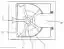
FIG. 1 is a side elevational view of the bulk material gathering apparatus in accordance with one embodiment of the invention;
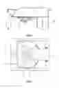
FIG. 2 is a top plan view thereof;
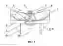
FIG. 3 is a cross-sectional view thereof along line A-A in FIG. 1.
DETAILED DESCRIPTION OF THE INVENTION
The invention provides in certain aspects a bidirectionally-rotating bulk material-gathering apparatus for use, e.g., in coal and ore mining and in specialized dock construction, which features equal gathering and transporting speed, high efficiency, easy alignment with conveying equipment, and smaller torque forces.
With reference to FIGS. 1-3, the hydraulic motor 2 having a cone shaft 4 is attached to the bucket 1 with the bolt 9 and the spring washer 10. The motor 2 is disposed underneath the bucket 1. A plurality of rotatable scraper blades 3 is disposed on the shaft 4 and fastened with the bolt 5 and the nut 6. The bolt 5 and the nut 6 are protected with the cap 7 secured by the screw 8. The blades 3 are disposed within the bucket 1, and the bucket 1 functions to collect bulk material dislodged and/or scraped into the bucket by the blades 3. The length of the blades 3 is chosen so that when rotating around the shaft 4, the blades periodically project outside of the bucket 1 and the bucket teeth 12 allowing the blades to scrape bulk material into the bucket 1.
Other structures found in conventional bulk material gathering machines are retained unchanged or with appropriate modifications. For example, the reclaiming head of the original bucket wheel machine may be removed. All remnants of the cantilever belt conveyor may be eliminated. The bucket wheel machine head may be dismantled. The lug support base may be fixedly welded on the cantilever belt conveyor. And, the front lug support base may be welded above the roller vertical centerline of the belt conveyor.
The apparatus of the invention achieves the purpose of automatic matter gathering by horizontal scratching. Bulk materials are scratched into the bucket with rotating blades powered by the hydraulic motor in order to transmit them to the discharge opening 15 formed by the bucket 1 and the discharge frame 14 and direct to the conveyor belt. Blade rotation (clockwise or counterclockwise) is smooth and material is continuously transmitted to the discharge opening 15 along the bucket slope, and on to the belt conveyer.
The blades can be extended outside the bucket teeth to a maximum scratch distance. The inclination angle between the ground and the blades (corresponding to cantilever belt conveyer inclination angle) shall not exceed 90 degrees and preferably remain in the range of between 15 degrees and 75 degrees.
The apparatus is applicable to the transportation of coal, ores, yellow sand stone, bulk materials, and other matter, and can be widely used in harbors, mines, steel plants, large stockyards, etc.
The invention provides the following advantages:
-
- 1) High production efficiency: The bidirectional rotatable apparatus uses a horizontal rotatable scraping method instead of the traditional vertical bucket wheel material-reclaiming method. A shovel is not used and materials are not hoisted. Power is saved and bucket capacity is increased. Therefore, an unexpected result is produced, the gathering and transporting of materials is performed at the same speed, which saves energy.
- 2) Improved design: The bucket is easily centered with the conveyor. This improves the forces acting on the conveyor eliminating unwanted torques. The strength and stiffness requirements of the conveyor belt are decreased, which increases efficiency and allows the head size to be reduced. This in turn reduces weight of the apparatus, increases the stability, and saves manufacturing cost.
- 3) The bulk material gathering apparatus of the invention is lighter which conventional machines, which lowers support and foundation requirements and makes the apparatus more versatile.
- 4) The invention overcomes various other disadvantages and shortcomings of conventional bulk matter gathering machines.
This invention is not to be limited to the specific embodiments disclosed herein and modifications for various applications and other embodiments are intended to be included within the scope of the appended claims. While this invention has been described in connection with particular examples thereof, the true scope of the invention should not be so limited since other modifications will become apparent to the skilled practitioner upon a study of the drawings, specification, and following claims.
All publications and patent applications mentioned in this specification are indicative of the level of skill of those skilled in the art to which this invention pertains. All publications and patent applications mentioned in this specification are herein incorporated by reference to the same extent as if each individual publication or patent application mentioned in this specification was specifically and individually indicated to be incorporated by reference.
Claims
What is claimed is:1. A material gathering apparatus, comprising:
a bucket (1);
a motor (2) having a shaft (4); and
a plurality of blades (3);
wherein
the hydraulic motor (2) is fixed below the bucket (1); and
the plurality of blades (3) are fixed within the bucket and are rotatable clockwise or counterclockwise around the shaft (4).
2. The apparatus of claim 1 further comprising bucket teeth (12) for latching onto bulk material.
3. The apparatus of claim 1 further comprising a discharge frame (14) forming a discharge opening (15) for transporting bulk material to a conveyor.
4. A method for gathering material using the apparatus of claim 3, comprising supplying power to said motor (2) and orienting the apparatus so that the blades (3) come in contact with the material, whereby said motor (2) turns the blades (3) in a clockwise or counterclockwise direction and the blades (3) gather material into the bucket (1).
5. The method of claim 4 wherein the material is moved along by the blades toward the discharge opening (15) and falls into the discharge opening (15).
6. The method of claim 4 wherein the blades rotate in a plane that forms an angle of between 15 degrees and 75 degrees with respect to the ground.
Images & Drawings included:
Sources:
- United States Patent and Trademark Office - verify current appl. status at the USPTO↗
Recent applications in this class:
- » 20250187856 2025-06-12
AUTONOMOUS DEVICES, SYSTEMS, AND METHODS FOR QUEUING FOLDED LAUNDRY - » 20250058982 2025-02-20
AUTONOMOUS DEVICES, SYSTEMS, AND METHODS FOR PACKING FOLDED LAUNDRY - » 20240132305 2024-04-25
Autonomous devices, systems, and methods for queuing folded laundry - » 20240059508 2024-02-22
Autonomous devices, systems, and methods for packing folded laundry - » 20230278814 2023-09-07
Autonomous devices, systems, and methods for packing folded laundry - » 20220135351 2022-05-05
Autonomous devices, systems, and methods for queuing folded laundry - » 20220112040 2022-04-14
Method and device for loading containers with packages