Ladder system, especially for vehicles
US20080210490A1
2008-09-04
11/915,119
2006-06-07
✅ Patent granted
US 8,006,803 B2
2011-08-30
WO; PCT/FR2006/001286; 20060607
WO; WO2006/131645; 20061214
Katherine Mitchell | Colleen M Quinn
2027-02-05
Abstract:
The invention relates to a ladder comprising a single post (1) provided with a fixing means (4) on the upper end (1S) thereof, said ladder comprising an anchoring means (9, 10) which is especially adapted to said fixing means (4) and is attached to the wall (7), and foldable supporting arms (3) which are connected to either side of the single post (1) in an articulated manner.
Assignee:
- AIRBUS FRANCE 623 🇫🇷 Toulouse, France
Interested in similar patents?
Get notified when new applications in this technology area are published.
Classification:
B63B27/146 » CPC main
Arrangement of ship-based loading or unloading equipment for cargo or passengers of ramps, gangways or outboard ladders ; Pilot lifts Pilot ladders or similar outboard ladders, e.g. bathing ladders; Pilot lifts
B60R3/02 » CPC further
Arrangements of steps or ladders facilitating access to or on the vehicle , e.g. running-boards Retractable steps or ladders, e.g. movable under shock
B64C1/24 » CPC further
Fuselages; Constructional features common to fuselages, wings, stabilising surfaces and the like Steps mounted on, and retractable within, fuselages
B64F1/315 » CPC further
Ground or aircraft-carrier-deck installations for embarking or disembarking passengers Mobile stairs
E06C1/36 » CPC further
Ladders in general with rigid longitudinal member or members; Ladders attached to structures, such as windows, cornices, poles, or the like Ladders suspendable by hooks or the like
E06C1/381 » CPC further
Ladders in general with rigid longitudinal member or members; Special constructions of ladders, e.g. ladders with more or less than two longitudinal members, ladders with movable rungs or other treads, longitudinally-foldable ladders Ladders with rungs or treads attached only to one rigid longitudinal member
E06C5/02 » CPC further
Ladders characterised by being mounted on undercarriages or vehicles Securing ladders on vehicles with rigid longitudinal members
E06C5/00 IPC
Ladders characterised by being mounted on undercarriages or vehicles Securing ladders on vehicles
Description
The present invention relates to a ladder system which can be used on board vehicles, especially on board civil aircraft, to climb over a wall belonging to said vehicles.
It will be clearly appreciated that the movements of such vehicles make it necessary for the ladder used to be able to be held firmly against said wall during its use. Furthermore, given the lack of space available on board, said ladder must be foldable so that it has a minimum space requirement when it is not being used.
For example, document U.S. Pat. No. 2,924,291 has already disclosed a boat ladder comprising:
-
- a means for hooking to a wall of said boat;
- a single post provided at its upper part with said hooking means;
- rungs arranged on said single post, on either side thereof, said rungs being hinged by their inner ends to said single post about pins which are orthogonal to said post so that said rungs can assume two end positions, namely:
- a folded-up position in which said rungs are applied against said single post with their outer end directed toward said upper part of said single post; and
- a deployed position in which said rungs are arranged orthogonally to said single post and locked downwardly by their inner ends bearing against said single post; and
- means for bearing against said wall, on either side of said single post.
In this known prior system, the stability of the ladder is not very good, in spite of the presence of said bearing means, since the hooking means consists of a wide hook intended to engage with the gunwale of the boat. Furthermore, said bearing means are formed as a single part which is hinged to the single post and, in the folded-up position along said post, said part has a relatively high space requirement.
The object of the present invention is to improve the system of the prior document recalled above in such a way as to achieve a high degree of stability when it is being used and a minimum possible space requirement during periods when it is not being used.
To that end, according to the invention, the ladder system comprising a ladder as mentioned above is noteworthy in that:
-
- an anchorage specially adapted to said hooking means of said ladder is affixed to said wall; and
- said bearing means comprise two arms which are arranged symmetrically with respect to said single post and are hinged by their inner end to said single post about pins which are orthogonal to said post so that said arms can assume two end positions, namely:
- a folded-up position in which the two arms are applied against said single post, on either side thereof, with their outer end directed toward said upper part of said single post; and
- a deployed position in which the two arms are arranged orthogonally to said single post and locked downwardly by their inner end bearing against said single post.
It is advantageous for the outer ends of the two arms to have the shape of arcs such that the two arms together have, in the deployed position, the at least approximate shape of a crescent.
It is also advantageous for the upper part of said single post to have an arc shape corresponding to that of said arms such that, when said arms are in the folded-up position, the outer ends thereof are at least partially superposed with the arc shape of said upper part of the single post.
The arc shapes of the outer ends of said arms and of said upper part of the single post may be angular.
Preferably, said single post, said rungs and said arms are produced from a tube having a square or rectangular cross section.
To further improve the stability of the ladder according to the present invention when in use, it may be assigned a plate bearing said anchorage adapted to the hooking means of the ladder, it being possible for said plate to be fastened to said wall or the like.
Thus, when said arms are in the deployed position, the outer ends thereof can bear against said plate. Co-acting positioning and retaining means are then advantageously provided, in part, at said outer ends of said arms and, in part, on said plate.
Preferably, in order to limit the number of rungs, these rungs are alternately arranged on one side and the other of said single post.
The figures of the appended drawing will clearly show how the invention can be implemented. In these figures, identical references denote like elements.
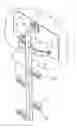
FIG. 1 is a perspective view of a ladder according to the present invention, in the deployed position.
FIG. 2 is a perspective view, from a different angle, of the ladder of FIG. 1, in the folded-up position.
FIG. 3 is a perspective view, similar to that of FIG. 2, showing said ladder in the deployed position and hooked to its anchorage.
The ladder, according to the present invention and represented in the figures, comprises a single post 1, rungs 2 and two bearing arms 3, said rungs 2 and said arms 3 being hinged to said single post 1.
The single post 1, the rungs 2 and the bearing arms 3 are produced from tubes of quadrangular, especially square, cross section, said tubes being made of aluminum, for example.
The single post 1 is essentially rectilinear, except at is upper part 1S, which is arced angularly with respect to the remaining rectilinear portion of said single post. At its free end, said arced upper part 1S bears a double hook 4.
The rungs 2 are distributed along the single post 1, in an alternating arrangement on either side thereof. Each of the rungs is hinged by its inner end 2I to said single post 1 about an off-center pin 5 which is orthogonal to said post 1.
Thus, the rungs 2 can assume:
-
- a folded-up end position (see FIG. 2) in which said rungs 2 are applied against the single post 1 with their outer end 2E directed toward the upper part 1S of said post; and
- a deployed end position (see FIGS. 1 and 3) in which said rungs 2 are arranged orthogonally to said single post 1 and locked downwardly (in the opposite direction to the upper part 1S of the single post 1) by their inner ends 2I bearing against the single post 1.
The two bearing arms 3 are arranged symmetrically with respect to the single post 1 and their outer ends 3E are arced angularly in a corresponding manner to the upper end 1S of the single post 1.
The two bearing arms 3 are hinged by their inner end 3I to said single post 1 about off-center pins 6 which are orthogonal to said post. Thus, the two bearing arms 3 can assume:
-
- a folded-up end position (see FIG. 2) in which they are applied against said single post, on either side thereof, with their arced outer ends 3E directed upwardly and superposed with the arced upper end 1S of the single post 1; and
- a deployed end position (see FIGS. 1 and 3) in which the two arms 3 are arranged orthogonally to the single post 1, forming a sort of crescent, and locked downwardly by their inner end 3I bearing against said single post 1.
As illustrated in FIG. 3, the ladder shown in FIGS. 1 and 2 can be put to use along a wall 7 by providing a plate 8 which can be fastened to said wall 7 and which bears a fixed anchorage for said ladder that is specially adapted to the double hook 4. In FIG. 3, said anchorage consists of a horizontal rod 9 held between two side mounts 10. Thus, the ladder can be fastened against the wall 7 by hooking the double hook 4 over the rod 9, the two arms 3 then being in the deployed position and bearing against the plate 8 by their outer ends 3E. The arced portions 1S and 3E of the post 1 and of the arms 3 can be designed such that, in the use position shown in FIG. 3, the single post 1 is at least approximately vertical.
To precisely determine the use position of said ladder and improve the stability of the ladder in said use position, co-acting positioning and retaining elements 11, 12 optionally having damping means (for example of the peg/hole type) are provided, on the one hand, at the ends 3E of the arms 3 and, on the other hand, on the plate 8.
Claims
1.-9. (canceled)
10. A ladder system for a wall (7), said ladder comprising:
a means (4) for hooking to said wall (7);
a single post (1) provided at its upper part (1S) with said hooking means (4);
rungs (2) arranged on said single post (1), on either side thereof, said rungs (2) being hinged by their inner ends (21) to said single post (1) about pins (5) which are orthogonal to said post so that said rungs can assume two end positions, namely:
a folded-up position in which said rungs (2) are applied against said single post (1) with their outer end (2E) directed toward said upper part (1S) of said single post (1); and
a deployed position in which said rungs (2) are arranged orthogonally to said single post (1) and locked downwardly by their inner ends (21) bearing against said single post (1); and
means (3) for bearing against said wall (7), on either side of said single post (1),
wherein:
an anchorage (9, 10) specially adapted to said hooking means (4) of said ladder is affixed to said wall; and
said bearing means comprise two arms (3) which are arranged symmetrically with respect to said single post (1) and are hinged by their inner end (3I) to said single post (1) about pins (6) which are orthogonal to said post so that said arms can assume two end positions, namely:
a folded-up position in which the two arms (3) are applied against said single post (1), on either side thereof, with their outer end (3E) directed toward said upper part (1S) of said single post (1); and
a deployed position in which the two arms (3) are arranged orthogonally to said single post (1) and locked downwardly by their inner end (31) bearing against said single post (1).
11. The system as claimed in claim 1, wherein it comprises a plate (8) which bears said anchorage (9, 10) and which can be fastened to said wall (7).
12. The system as claimed in claim 2, wherein, when said arms (3) are in the deployed position, the outer ends (3E) thereof bear against said plate (8).
13. The system as claimed in claim 3, wherein it comprises co-acting positioning and retaining means (11, 12) provided, in part, at the outer ends (3E) of said arms (3) and, in part, on said plate (8).
14. A ladder for the system specified in claim 1, comprising:
a single post (1) provided at its upper part (1S) with a hooking means (4); and
rungs (2) arranged on said single post (1), on either side thereof, said rungs (2) being hinged by their inner ends (21) to said single post (1) about pins (5) which are orthogonal to said post so that said rungs can assume two end positions, namely:
a folded-up position in which said rungs (2) are applied against said single post (1) with their outer end (2E) directed toward said upper part (1S) of said single post (1); and
a deployed position in which said rungs (2) are arranged orthogonally to said single post (1) and locked downwardly by their inner ends (21) bearing against said single post (1),
wherein it additionally comprises two arms (3) arranged symmetrically with respect to said single post (1), the inner ends (3E) having the shape of arcs such that the two arms (3) together have, in the deployed position, the at least approximate shape of a crescent, and said arms (3) being hinged by their inner end (31) to said single post (1) about pins (6) which are orthogonal to said post so that said arms can assume two end positions, namely:
a folded-up position in which the two arms (3) are applied against said single post (1), on either side thereof, with their outer end (3E) directed toward said upper part (1S) of said single post (1); and
a deployed position in which the two arms (3) are arranged orthogonally to said single post (1) and locked downwardly by their inner end (31) bearing against said single post (1).
15. The ladder as claimed in claim 5, wherein the upper part (1S) of said single post (1) has an arc shape corresponding to that of said arms (3) such that, when said arms are in the folded-up position, the outer ends (3E) thereof are at least partially superposed with the arc shape of said upper part (1S) of the single post (1).
16. The ladder as claimed in claim 5, wherein the arc shapes of the outer ends (3E) of said arms (3) and of said upper part (1S) of the single post (1) are angular.
17. The ladder as claimed in claim 5, wherein said single post (1), said rungs (2) and said arms (3) are produced from a tube having a square or rectangular cross section.
18. The ladder as claimed in claim 5, wherein said rungs (2) are alternately on one side and the other of said single post (1).
Images & Drawings included:

Sources:
- United States Patent and Trademark Office - verify current appl. status at the USPTO↗
Recent applications in this class:
- » 20250128790 2025-04-24
RETRACTABLE LOW-PROFILE FOLD-DOWN STEP SYSTEM FOR BOATS - » 20240227986 2024-07-11
BOARDING PLATFORM - » 20240190536 2024-06-13
POCKET STYLE FOLDING BOAT LADDER ASSEMBLY - » 20240017797 2024-01-18
Hydraulic marine vessel door assembly - » 20230415857 2023-12-28
Watercraft swim platform with deployable steps - » 20230234676 2023-07-27
ILLUMINATED MARINE LADDER - » 20220363348 2022-11-17
Watercraft swim platform with deployable steps - » 20220363347 2022-11-17
Powered retractable ladder - » 20220126953 2022-04-28
Stern platform arrangement and marine vessel - » 20220089254 2022-03-24
ATTACHMENTS FOR A COLLAPSIBLE MARINE LADDER
Recent applications for this Assignee:
- » 20120328385 2012-12-27
Machining means for ceiling fixed parts - » 20120325958 2012-12-27
Aircraft with rear annular tail - » 20120284006 2012-11-08
Method of determining the particle sensitivity of electronic components - » 20110226899 2011-09-22
Autonomous plane architecture for the transport and the replacement of propulsion engines - » 20110198918 2011-08-18
Device and method for emergency electricity supply on board an aircraft - » 20110004361 2011-01-06
Method and device for estimating the forces exerted on a control surface of an aircraft - » 20100332111 2010-12-30
Device for guiding an aircraft along a flight trajectory - » 20100319801 2010-12-23
System for weaving a continuous angle - » 20100301161 2010-12-02
Acoustic coating for an aircraft incorporating a frost treatment system by joule effect - » 20100297390 2010-11-25
Self-stabilised stiffener enabling element recovery