Fan and fan frame thereof
US20080219837A1
2008-09-11
11/964,408
2007-12-26
✅ Patent granted
US 8,926,278 B2
2015-01-06
-
-
Edward Look | Aaron R Eastman
Birch, Stewart, Kolasch & Birch, LLP
2031-12-05
Abstract:
A fan has a fan, an impeller and a motor. The impeller is disposed in the fan frame, and the motor is disposed in the fan frame for driving the impeller. The fan frame has a housing, a base and at least one connecting element. The housing has an inlet and an outlet, and the base is disposed in the housing and at the outlet. The connecting element is disposed between the housing and the base. The base has a first airflow guiding structure disposed on the circumference of the base. The housing has a second airflow guiding structure disposed on the inner circumference thereof and adjacent to the outlet. The first airflow guiding structure and the second airflow guiding structure are correspondingly disposed.
Assignee:
- DELTA ELECTRONICS, INC. 1,322 🇹🇼 Taoyuan Hsien, Taiwan
Applicant:
Interested in similar patents?
Get notified when new applications in this technology area are published.
Classification:
F04D29/54 IPC
Details, component parts, or accessories; Casings; Connections of working fluid for axial pumps Fluid-guiding means, e.g. diffusers
F04D29/544 » CPC further
Details, component parts, or accessories; Casings; Connections of working fluid for axial pumps; Fluid-guiding means, e.g. diffusers; Specially adapted for elastic fluid pumps; Bladed diffusers Blade shapes
F01D1/02 IPC
Non-positive-displacement machines or engines, e.g. steam turbines with stationary working-fluid guiding means and bladed or like rotor, e.g. multi-bladed impulse steam turbines
F01D25/24 IPC
Component parts, details, or accessories, not provided for in, or of interest apart from, other groups Casings ; Casing parts, e.g. diaphragms, casing fastenings
F04D25/0613 » CPC main
Pumping installations or systems; Units comprising pumps and their driving means the pump being electrically driven the electric motor being specially adapted for integration in the pump the electric motor being of the inside-out type, i.e. the rotor is arranged radially outside a central stator
F04D29/542 » CPC further
Details, component parts, or accessories; Casings; Connections of working fluid for axial pumps; Fluid-guiding means, e.g. diffusers; Specially adapted for elastic fluid pumps Bladed diffusers
F04B39/12 IPC
Component parts, details, or accessories, of pumps or pumping systems specially adapted for elastic fluids, not otherwise provided for in, or of interest apart from, groups - Casings; Cylinders; Cylinder heads; Fluid connections
F04D25/06 IPC
Pumping installations or systems; Units comprising pumps and their driving means the pump being electrically driven
Description
CROSS REFERENCE TO RELATED APPLICATIONS
This Non-provisional application claims priority under 35 U.S.C. §119(a) on Patent Application No(s). 096107617, filed in Taiwan, Republic of China on Mar. 6, 2007, the entire contents of which are hereby incorporated by reference.
BACKGROUND OF THE INVENTION
1. Field of Invention
The present invention relates to a fan and a fan frame thereof, and in particular to a fan and a fan frame thereof that can lower the noise and increase the efficiency.
2. Related Art
The efficiency of a fan is indicated by the air pressure and air volume that it can generate. To increase the air pressure and volume, one method is to increase its rotation speed. However, noises come with high-speed rotations. To solve this problem, the prior art modifies the design of blades. Nevertheless, this method is both difficult and impractical. In the overall structural design of the fan, changing the fan frame is another way of promoting the fan efficiency.
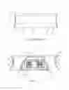
FIG. 1 is a cross-sectional view of a conventional fan 1, which has a fan frame 10. The fan frame 10 includes a housing 103, a base 104 and at least one connecting element 105 connecting the housing 103 and the base 104. The fan frame 10 also has an inlet 101 and an outlet 102. The base 104 is disposed at the outlet 102. The housing 103 has a first guiding angle 108 and a second guiding angle 109 at the inlet 101 and the outlet 102, respectively. The first guiding angle 108 and the second guiding angle 109 are slant surfaces for guiding the airflow in and out.
However, as the airflow is guided into the fan through the inlet 101, the airflow is directly guided out afterwards because the base 104 is a vertical structure. That is, the pressure of the airflow is not increased. Moreover, when the airflow passes by the outlet 102, the slant surface design of the second guiding angle 109 guides it out without any merging effect. After the airflow leaves the outlet 102, a vortex is produced at the outlet 102, which results in noises so that a negative effect on the efficiency of the fan is induced.
SUMMARY OF THE INVENTION
In view of the foregoing, the present invention is to provide a fan and a fan frame thereof. Through changes in the design of the fan frame and the airflow guiding structure on the base, the airflow speed can be increased to promote the air pressure and volume. Moreover, the present invention can prevent vortices from occurring at the outlet, so as to reduce noises during the fan operation.
To achieve the above, the present invention discloses a fan frame including a housing, a base and at least one connecting element. The housing has an inlet and an outlet, and the base is disposed at the outlet. The connecting element is disposed between the housing and the base. The base has a first airflow guiding structure disposed on the circumference of the base. The housing has a second airflow guiding structure disposed on the inner circumference of the housing and adjacent to the outlet. The first airflow guiding structure and the second airflow guiding structure are disposed correspondingly.
To achieve the above, the present invention also discloses a fan including a fan frame, an impeller and a motor. The fan frame includes a housing, a base and at least one connecting element. The housing has an inlet and an outlet, the base is disposed at the outlet, and the connecting element is disposed between the housing and the base. The base has a first airflow guiding structure disposed on the circumference of the base and adjacent to the outlet. The housing has a second airflow guiding structure disposed on the inner circumference of the housing and adjacent to the outlet. The first airflow guiding structure and the second airflow guiding structure are disposed correspondingly. The impeller and the motor are disposed in the fan frame, and the motor is for driving the impeller.
As mentioned above, in the present invention, the outgoing airflow can be converging by using the airflow guiding structures disposed on the base and the fan frame. Compared with the related art, the fan frame of the present invention can increase the speed of the airflow at the outlet, thereby increasing the air pressure and volume. Moreover, the present invention can prevent vortices from occurring at the outlet so as to reduce noises during the operation of the fan.
BRIEF DESCRIPTION OF THE DRAWINGS
The present invention will become more fully understood from the detailed description and accompanying drawings, which are given for illustration only, and thus are not limitative of the present invention, and wherein:
FIG. 1 is a cross-sectional view of a conventional fan;
FIG. 2 is a cross-sectional view of a fan according to an embodiment of the present invention; and
FIG. 3 shows the curves of the air volume and air pressure of the conventional fan and the fan of the present invention.
DETAILED DESCRIPTION OF THE INVENTION
The present invention will be apparent from the following detailed description, which proceeds with reference to the accompanying drawings, wherein the same references relate to the same elements.
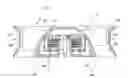
FIG. 2 is a cross-sectional view of a fan 2 according to an embodiment of the present invention. Referring to FIG. 2, the fan 2 of the embodiment is an axial-flow fan. The fan 2 includes a fan frame 20, an impeller 21 and a motor 22. The impeller 21 and the motor 22 are disposed in the fan frame 20. The fan frame 20 has a housing 203 with a through hole so as to form an inlet 201 and an outlet 202. The fan frame 20 has a roughly square, circular, elliptical or rhombus shape. Besides, the fan frame 20 includes a base 204 and at least one connecting element 205. The connecting element 205 is disposed between the housing 203 and the base 204 for supporting the base 204. In this embodiment, the connecting element 205 can be a rib or a stationary blade. The connecting element 205 can be integrally formed with the base 204 and the housing 203 as a single unit. The impeller 21 has a hub 211 and several blades 212 disposed around the hub 211. The outer radius of the hub 211 increases gradually from the inlet to the outlet. The motor 22 is disposed in the fan frame 20. The impeller 21 is disposed on the base 204 of the fan frame 20, and is driven by the motor 22.
With reference to FIG. 2, the base 204 includes a first airflow guiding structure 206. The base 204 is preferably disposed at the outlet 202. The first airflow guiding structure 206 is disposed on the circumference of the base 204 and adjacent to the outlet 202. The hub 211 has a curved or slant surface that corresponds to the profile of the first airflow guiding structure 206. The fan frame 20 has a second airflow guiding structure 207 disposed on the inner circumference of the housing 203 of the fan frame and adjacent to the outlet 202. In particular, the first airflow guiding structure 206 and the second airflow guiding structure 207 are disposed correspondingly and can be integrally formed with the base 204 and the housing 203, respectively
It is noted that in order to increase the airflow speed and reduce the noise of the fan 2, the first airflow guiding structure 206 and second airflow guiding structure 207 have at least one slant surface and/or at least one curved surface. For example, the first airflow guiding structure 206 can include a single slant surface, a single curved surface, several slant surfaces, several curved surfaces, and/or their combinations. In this embodiment, the first airflow guiding structure 206 has a slant surface extending along the outlet 202 toward the housing 203. Therefore, when air flows through the first airflow guiding structure 206, it becomes a narrow stream due to the reduced channel. The second airflow guiding structure 207 has a curved surface with a curvature radius decreasing along the direction toward the outlet 202. A tangential direction of the curvature radius near the outlet 202 is about perpendicular to the outlet 202, so that the airflow does not expand.
In this embodiment, the fan frame 203 has a guiding angle 208 at the inlet 201. When the motor 22 operates to rotate the impeller 21, a pressure difference is produced between the fan 2 and the external environment because of the operation of the blades 212 on the hub 211. The airflow thus enters via the inlet 201 and is guided into the fan frame 20 by the guiding angle 208, flowing toward the outlet 202. When the airflow is guided by the guiding angle 208 into the fan frame 20 and passes by the first airflow guiding structure 206 and the second airflow guiding structure 207, the reduced airflow channel squeezes the airflow and accelerates its speed due to the design. At the same time, the airflow pressure increases. The curved-surface design of the second airflow guiding structure 207 changes the flowing direction of the airflow so that when the airflow leaves the outlet 202, the airflow direction is perpendicular to the outlet 202. This prevents vortices from occurring at the outlet 202 and helps reducing noises during the operation of the fan 2.
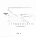
FIG. 3 shows the characteristic curve of the air pressure and air volume of the fan of the present invention compared with those of the conventional fan. Experimental data indicate that the fan of the present invention can effectively increase both the air pressure and volume. For example, at the same air volume, the maximum air pressure of the present invention is greater than that of the conventional fan by about 17%.
In summary, by using the airflow guiding structures disposed on the base and the fan frame, the outgoing airflow can be converging. Compared with the conventional fan, the fan frame of the present invention can increase the speed of the airflow at the outlet, thereby increasing the air pressure and volume. Moreover, the present invention can prevent vortices from occurring at the outlet, so as to reduce noises during the operation of the fan.
Although the present invention has been described with reference to specific embodiments, this description is not meant to be construed in a limiting sense.
Claims
What is claimed is:1. A fan frame, comprising:
a housing having an inlet and an outlet;
a base, disposed in the housing and at the outlet; and
at least one connecting element disposed between the housing and the base;
wherein the base comprises a first airflow guiding structure disposed on a circumference of the base, the housing comprises a second airflow guiding structure disposed on an inner circumference of the housing and adjacent to the outlet, and the first airflow guiding structure and the second airflow guiding structure are disposed correspondingly.
2. The fan frame of claim 1, wherein the first airflow guiding structure and the base are integrally formed as a single unit.
3. The fan frame of claim 1, wherein the first airflow guiding structure comprises at least one slant surface and/or at least one curved surface.
4. The fan frame of claim 3, wherein the first airflow guiding structure extends along the outlet toward the housing.
5. The fan frame of claim 1, wherein the second airflow guiding structure and the housing are integrally formed as a single unit.
6. The fan frame of claim 1, wherein the second airflow guiding structure comprises a curved surface.
7. The fan frame of claim 6, wherein a curvature radius of the curved surface decreases toward the outlet, and a line tangent to the curved surface near the
Various modifications of the disclosed embodiments, as well as alternative embodiments, will be apparent to persons skilled in the art. It is, therefore, contemplated that the appended claims will cover all modifications that fall within the true scope of the present invention. outlet is about perpendicular to the outlet.
8. The fan frame of claim 1, wherein the connecting element, the base and the housing are integrally formed as a single unit, and the connecting element comprises a rib or a stationary blade.
9. A fan, comprising:
a fan frame, comprising:
a housing having an inlet and an outlet,
a base disposed in the housing and at the outlet, and
at least one connecting element disposed between the housing and the base, wherein the base comprises a first airflow guiding structure disposed on a circumference of the base and adjacent to the outlet so that an airflow channel decreases correspondingly;
an impeller disposed in the fan frame; and
a motor disposed in the fan frame for driving the impeller.
10. The fan of claim 9, wherein the housing has a second airflow guiding structure disposed on an inner circumference of the housing and adjacent to the outlet, and the first airflow guiding structure and the second airflow guiding structure are disposed correspondingly.
11. The fan of claim 9, wherein the first airflow guiding structure and the base are integrally formed as a single unit.
12. The fan of claim 9, wherein the first airflow guiding structure comprises at least one slant surface and/or at least one curved surface.
13. The fan of claim 9, wherein the first airflow guiding structure extends along the outlet toward the housing.
14. The fan of claim 9, wherein the second airflow guiding structure and the housing are integrally formed as a single unit.
15. The fan of claim 9, wherein the second airflow guiding structure comprises a curved surface.
16. The fan of claim 15, wherein a curvature radius of the curved surface decreases toward the outlet, and a line tangent to the curved surface near the outlet is about perpendicular to the outlet.
17. The fan of claim 9, wherein the connecting element, the base and the housing are integrally formed as a single unit, and the connecting element comprises a rib or a stationary blade.
18. The fan of claim 9, wherein the housing roughly has a square, circular, elliptical or rhombus shape, and the fan is an axial-flow fan.
19. The fan of claim 9, wherein the impeller comprises a hub and a plurality of blades disposed around the hub, and an outer diameter of the hub gradually increases from the inlet toward the outlet.
20. The fan of claim 9, wherein the impeller comprises a hub and a plurality of blades disposed around the hub, and the hub has a curved or slant surface corresponding to a profile of the first airflow guiding structure.
Images & Drawings included:
Sources:
- United States Patent and Trademark Office - verify current appl. status at the USPTO↗
Similar patent applications:
- » 20080138191
Fan with impellers coupled in series and fan frame thereof - » 20080232961
FAN AND FAN FRAME THEREOF - » 20080101919
Fan and fan frame thereof - » 20050207886
Centrifugal fan and fan frame thereof - » 20060257254
Heat dissipation apparatus and fan frame thereof - » 20070065281
Fan and fan frame thereof - » 20070092373
Centrifugal fan and fan frame thereof - » 20060002790
Fan assembly and fan frame thereof - » 20070160462
Centrifugal fan and fan frame thereof - » 20080247864
Fan and fan frame thereof
Recent applications in this class:
- » 20220381251 2022-12-01
PAP system blower - » 20210010480 2021-01-14
Illumination fan - » 20200248702 2020-08-06
Rotary drive for an impeller and motor assembly with gas and rolling bearings arranged in housing structure - » 20200040900 2020-02-06
Thin cooling fan - » 20190390678 2019-12-26
CENTRIFUGAL FAN - » 20190331122 2019-10-31
Illumination fan - » 20190285075 2019-09-19
Centrifugal fan comprising a sidewall and plurality of air deflectors forming a plurality of airflow entry tunnels to sequentially expand a flow channel outwardly in a radial direction - » 20180112669 2018-04-26
Dual operation centrifugal fan apparatus and methods of using same - » 20180066664 2018-03-08
THIN COOLING FAN - » 20180003183 2018-01-04
Shrouded fan impeller with reduced cover overlap
Recent applications for this Assignee:
- » 20190242389 2019-08-08
Inner-rotor fan - » 20180128108 2018-05-10
Axial fan and control method thereof - » 20180074389 2018-03-15
Projection apparatus comprising phosphor wheel coated with phosphor agents for converting waveband light - » 20180042082 2018-02-08
LED lighting module having tunable correlated color temperature and control method thereof - » 20170151670 2017-06-01
Tool calibration apparatus of robot manipulator - » 20170020025 2017-01-19
Equipment cabinet and slidable-and-rotatable rack assembly thereof - » 20160305508 2016-10-20
Speed reducer - » 20160295733 2016-10-06
Clip and electronic device using same - » 20160236131 2016-08-18
Dust collector and projection apparatus with same - » 20160211768 2016-07-21
Power conversion device and controlling method thereof