Projection lens with high resolution and reduced overall length
US20090052055A1
2009-02-26
11/952,974
2007-12-07
✅ Patent granted
US 7,742,243 B2
2010-06-22
-
-
Darryl J Collins
2028-03-21
Abstract:
An exemplary projection lens includes, in this order from the magnification side to the minification side thereof, a negative lens group of negative fraction power, and a positive lens group of positive fraction power. The projection lens satisfies the formulas of: −2.5<F1/F<−1.5; and 1.3<F2/F<1.5, where F1, F2, and F respectively represent the effective focal lengths of the negative lens group, the positive lens group, and the projection lens.
Assignee:
- HON HAI PRECISION INDUSTRY CO., LTD. 12,833 🇹🇼 Tu-Cheng, Taiwan
- HON HAI PRECISION INDUSTRY CO., LTD. 2,357 🇹🇼 Tu-Cheng, Taipei Hsien, Taiwan
Interested in similar patents?
Get notified when new applications in this technology area are published.
Classification:
G02B13/16 » CPC main
Optical objectives specially designed for the purposes specified below for use in conjunction with image converters or intensifiers, or for use with projectors, e.g. objectives for projection TV
G02B9/64 » CPC further
Optical objectives characterised both by the number of the components and their arrangements according to their sign, i.e. + or - having more than six components
G02B3/02 IPC
Simple or compound lenses with non-spherical faces
G02B9/08 IPC
Optical objectives characterised both by the number of the components and their arrangements according to their sign, i.e. + or - having two components only two + components arranged about a stop
G02B9/60 IPC
Optical objectives characterised both by the number of the components and their arrangements according to their sign, i.e. + or - having five components only
G02B9/04 IPC
Optical objectives characterised both by the number of the components and their arrangements according to their sign, i.e. + or - having two components only
Description
BACKGROUND
1. Technical Field
The invention relates to projection lens and, particularly, relates to a projection lens having a high resolution and a small overall length.
2. Description of Related Art
In order to obtain a sharp projection image and reduce a size of projectors, such as digital light processing (DLP) projectors, liquid crystal display (LCD) projectors, or liquid crystal on silicon (LCOS) projectors, projection lenses with high resolution but short overall length (the distance between the magnification-side surface of such a projection lens and a surface of a spatial light modulator (SLM), e.g., digital micro-mirror device (DMD), LCD panel, or LCOS panel, equipped in a projector facing the projection lens) are needed. Factors affecting both the resolution and the overall length of the projection lens, such as the number and position of lenses employed, the refraction power distributions of the employed lenses, and the shape of each of the employed lenses, complicate any attempt at increasing resolution and shortening overall length of projection lenses. For example, reducing the number of lenses can shorten the overall length of the projection lens, but resolution will suffer, conversely, increasing the number of lenses can increase resolution, but increases overall length of the projection lens.
Therefore, it is desirable to provide a projection lens which can overcome the abovementioned problems.
SUMMARY
In a present embodiment, a projection lens includes, in this order from the magnification side to the minification side thereof, a negative lens group having negative fraction of power, and a positive lens group having positive fraction of power. The projection lens satisfies the formulas of: −2.5<F1/F<−1.5; and 1.3<F2/F<1.5, where F1, F2, and F respectively represent the effective focal lengths of the negative lens group, the positive lens group, and the projection lens.
BRIEF DESCRIPTION OF THE DRAWINGS
Many aspects of the present projection lens should be better understood with reference to the following drawings. The components in the drawings are not necessarily drawn to scale, the emphasis instead being placed upon clearly illustrating the principles of the present projection lens. Moreover, in the drawings, like reference numerals designate corresponding parts throughout the several views.
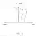
FIG. 1 is a schematic view of a projection lens in accordance with an embodiment.
FIG. 2-4 are graphs respectively showing spherical aberration, field curvature, and distortion occurring in the projection lens in accordance with a first exemplary embodiment.
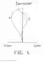
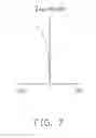
FIG. 5-7 are graphs respectively showing spherical aberration, field curvature, and distortion occurring in the projection lens in accordance with a second exemplary embodiment.
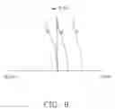
FIG. 8-10 are graphs respectively showing spherical aberration, field curvature, and distortion occurring in the projection lens in accordance with a third exemplary embodiment.
DETAILED DESCRIPTION OF THE EMBODIMENTS
Embodiments of the present projection lens will now be described in detail with reference to the drawings.
Referring to FIG. 1, the projection lens 100, according to an exemplary embodiment, is opportunely used in LCOS projectors. Such an LCOS projector commonly equips with an LCOS panel (not shown) that has a surface 99 facing the projection lens 100. The projection lens 100 includes, in this order from the magnification side to the minification side thereof, a negative lens group 10, and a positive lens group 20. The negative lens group 10 has a negative refraction of power, while the positive lens group 20 has a positive refraction of power. The projection lens 100 satisfies the formulas of: (1)−2.5<F1/F<−1.5; and (2) 1.3<F2/F<1.5. Where F1, F2, and F respectively represent the effective focal lengths of the negative lens group 10, the positive lens group 20, and the projection lens 100.
The formulas (1), (2) are adapted for distributing the fraction power of the lens groups 10, 20, to limit the overall length of the projection lens 100, and control/correct aberrations occurring in the projection lens 100 within an acceptable level. As for formula (1), F1/F>−2.5 is configured to limit the overall length of the projection lens 100, plus widen the field angle of the projection lens 100; F1/F<−1.5 is adapted to control aberrations, especially distortion, caused by the negative lens group 10. Formula (2) is adapted to efficiently correct aberrations caused by the negative lens group 10, and to obtain a telecentric projection lens 100 with short overall length. Specifically, if F2/F>1.3 is not satisfied, aberrations may be insufficiently corrected, and the projection lens 100 may lose the telecentric characteristic, conversely, if F2/F<1.5 is not satisfied, aberrations may be over corrected, and attempt at shortening the overall length of the projection lens 100 may fail.
Also, the projection lens 100 satisfies the formula: (3) Lb/F>1.6, where Lb is the rear focal length of the projection lens 100 (the distance between the minifcation-side surface of the projection lens 100 and the surface 99). This formula is for increasing the rear focal length Lb to provide sufficient space to accommodate an arrangement of a polarizer 98, a half-wave plate 97, and a polarization beam splitter (PBS) prism 96 of the LCOS projector.
Opportunely, the projection lens 100 also satisfies the formula: (4) 0.24<D12/F<0.5, where D12 is the distance between the lens groups 10, 20 on the optical axis of the projection lens 100. In detail, D12/F<0.5 is for controlling the overall length of the projection lens 100, and D12/F>0.24 is to provide sufficient space to allow focus adjustment of the projection lens 100.
Specifically, the negative lens group 10 includes, in this order from the magnification side to the minification side of the projection lens 100, a first lens 11 of negative refraction power, a second lens 12 of positive refraction power, a third lens 13 of negative refraction power, and a fourth lens 14 of positive refraction power. In order to efficiently control aberrations caused by the negative lens group 10, at least one of the four lenses 11˜14 has at least one aspherical surface (i.e., aspherical lens), whereas, in order to reduce cost of the projection lens 100, spherical lenses are preferably used in the projection lens 100. Therefore, the negative lens group 10 of this embodiment includes only one aspherical lens, e.g., aspherical first lens 11 or second lens 12, to balance the controlling of aberrations and contribute to the reduction of cost.
The positive lens group 20 includes, in this order from the magnification side to the minification side of the projection lens 100, a fifth lens 21 of positive refraction power, a sixth lens 22 of negative refraction power, a seventh lens 23 of positive refraction power, and a eighth lens 24 of positive refraction power. For similar reasons as above, the positive lens group 20 includes only one aspherical lens, e.g., aspherical seventh lens 23.
More specifically, the projection lens 100 further includes an aperture stop 95. The aperture stop 95 is interposed between the fifth lens 21 and the sixth lens 22 so as to block off-axis light rays from the sixth lens 22 entering the fifth lens 21, and thereby prevents too much distortion occurring in the projection lens 100 (the off-axis light rays are the main cause of distortion).
In order to control chromatic aberration occurring in the projection lens 100, at least one of the lenses 11˜14 of the negative lens group 10 satisfies the formula: (5) V1>55, and n1>1.5, where V1, n1 respectively represent the Abbe number and the refractive index of the at least one of the lenses 11˜14. In addition, at least one of the lenses 21˜24 of the positive lens group 20 satisfies the formula: (6) V2>60, where V2 is the Abbe number of the at least one of the lenses 21˜24.
Opportunely and specifically, except the aspherical lenses, e.g., aspherical lens 11, 12, or 23, the lenses of the projection lens 100 is advantageously a spherical glass lens to reduce cost of the projection lens 100 and control chromatic aberration occurring in the projection lens 100. As for the aspherical lenses, each of their surfaces is shaped according to the formula:
x - ch 2 1 + 1 - ( k + 1 ) c 2 h 2 + ∑ Aih i ,
where h is a height from the optical axis of the projection lens 100 to the aspherical surface, c is a vertex curvature, k is a conic constant, and Ai are i-th order correction coefficients of the aspheric surfaces.
Detailed examples of the projection lens 100 are given below in company with FIGS. 2-10, but it should be noted that the projection lens is not limited to these examples. Listed below are the symbols used in these detailed examples:
FNo: F number;
2ω: field angle;
R: radius of curvature;
d: distance between surfaces on the optical axis of the projection lens 100;
Nd: refractive index of lens; and
V: Abbe constant.
When projecting an image, the image is modulated by the LCoS panel, and projects from the surface 99, transmits through the polarizer 98, the half-wave plate 97, the PBS prism 96, the projection lens 100, and finally projects onto a screen (not shown).
Example 1
Tables 1, 2 show the lens data of Example 1, wherein F=21.58 mm, F1=−38.85 mm, F2=30.425 mm, FNo=2.45; 2ω=57.4°, and the second lens 12 and the seventh lens 23 is aspherical lens.
| TABLE 1 | ||||
| d | ||||
| Surface | R (mm) | (mm) | Nd | V |
| Magnification-side surface of the | 56.088 | 1.5 | 1.589 | 61.135 |
| first lens 11 | ||||
| Minification-side surface | 23.041 | 2.111 | — | — |
| of the first lens 11 | ||||
| Magnification-side surface of the | 66.179 | 4.045 | 1.6073 | 26.65 |
| second lens 12 | ||||
| Minification-side surface of the | −39.229 | 2.771 | — | — |
| second lens 12 | ||||
| Magnification-side surface of the | −79.672 | 1.5 | 1.571 | 50.8 |
| third lens 13 | ||||
| Minification-side surface | 13.178 | 3.771 | — | — |
| of the third lens 13 | ||||
| Magnification-side surface of the | −35.77 | 3.156 | 1.744 | 44.786 |
| fourth lens 14 | ||||
| Minification-side surface of the | −24.669 | 5.28 | — | — |
| fourth lens 14 | ||||
| Magnification-side surface of the | 43.254 | 3.481 | 1.589 | 61.135 |
| fifth lens 21 | ||||
| Minification-side surface of | −19.618 | 0.15 | — | — |
| the fifth lens 21 | ||||
| Surface of aperture stop 95 | infinite | 9.834 | — | — |
| Magnification-side surface of the | −25.202 | 1.5 | 1.8467 | 23.78 |
| sixth lens 22 | ||||
| Minification-side surface | 32.223 | 3.46 | — | — |
| of the sixth lens 22 | ||||
| Magnification-side surface of the | −49.8 | 7.1 | 1.5247 | 56.26 |
| seventh lens 23 | ||||
| Minification-side surface of the | −16.129 | 0.246 | — | — |
| seventh lens 23 | ||||
| Magnification-side surface of the | 72.513 | 7.946 | 1.6968 | 55.53 |
| eighth lens 24 | ||||
| Minification-side surface of the | −29.765 | 2.15 | — | — |
| eighth lens 24 | ||||
| Magnification-side surface | infinite | 22 | 1.6477 | 33.848 |
| of the PBS prism 96 | ||||
| Minification-side surface | infinite | 2 | — | — |
| of the PBS prism 96 | ||||
| Magnification-side surface of the | infinite | 0.7 | 1.5184 | 61.7 |
| half-wave plate 97 | ||||
| Minification-side surface of | infinite | 1 | — | — |
| the half-wave plate 97 | ||||
| Magnification-side surface of the | infinite | 0.7 | 1.523 | 58.57 |
| polarizer 98 | ||||
| Minification-side surface of the | infinite | 8 | — | — |
| polarizer 98 | ||||
| The surface 99 | infinite | — | — | — |
| TABLE 2 | |
| Surface | Aspherical coefficient |
| Magnification-side | k = −10.97392; A4 = 1.82963E−5; |
| surface of the | A6 = −9.26848E−8; A8 = 5.59189E−10; |
| second lens 12 | A10 = −1.98742E−12 |
| Minification-side | k = −22.43766; A4 = 3.49E−6; A6 = 2.72E−8; |
| surface of the | A8 = 7.02E−11; A10 = −7.80E−13 |
| second lens 12 | |
| Magnification-side | k = −79.16789; A4 = −1.08162E−4; |
| surface of the | A6 = 9.00E−07; A8 = −9.89E−9; |
| seventh lens 23 | A10 = 3.47E−11 |
| Minification-side | k = 0.4065924; A4 = 1.07E−5; A6 = 8.96E−9; |
| surface of the | A8 = 2.79E−10; A10 = −2.67E−12 |
| seventh lens 23 | |
As illustrated in FIG. 2, the curves f, d, and c are respective spherical aberration characteristic curves of f light (wavelength: 486.1 nm), d light (587.6 nm), and c light (656.3 nm) occurring in the projection lens 100 of Example 1. Obviously, spherical aberration occurring in projection lens 100 of Example 1 is in a range of: −0.1 mm˜0.1 mm. In FIG. 3, the curves t and s are the tangential field curvature curve and the sagittal field curvature curve respectively. Clearly, field curvature occurring in the projection lens 100 of Example 1 is limited to a range of: −0.1 mm˜0.1 mm. In FIG. 4, distortion occurring in the projection lens 100 of Example 1 is limited to be within the range of: −2%˜2%.
Example 2
Tables 3, 4 show the lens data of EXAMPLE 2, wherein F=20.57 mm, F1=−43.378 mm, F2=29.585 mm, FNo=2.44; 2ω=56.98°, and the second lens 12 and the seventh lens 23 is aspherical lens.
| TABLE 3 | ||||
| Surface | R (mm) | d (mm) | Nd | V |
| Magnification-side surface of the | 56.37951 | 1.5 | 1.5163 | 64.142 |
| first lens 11 | ||||
| Minification-side surface of the first | 19.45174 | 2.784273 | — | — |
| lens 11 | ||||
| Magnification-side surface of the | 67.52031 | 4.063589 | 1.6073 | 26.65 |
| second lens 12 | ||||
| Minification-side surface of the | −35.39937 | 1.838138 | — | — |
| second lens 12 | ||||
| Magnification-side surface of the | −115.634 | 1.5 | 1.5225 | 59.8354 |
| third lens 13 | ||||
| Minification-side surface of the third | 12.79318 | 4.061006 | — | — |
| lens 13 | ||||
| Magnification-side surface of the | −33.31014 | 3.632139 | 1.6204 | 60.2896 |
| fourth lens 14 | ||||
| Minification-side surface of the | −22.97251 | 5.274921 | — | — |
| fourth lens 14 | ||||
| Magnification-side surface of the | 47.65653 | 3.315928 | 1.589 | 61.135 |
| fifth lens 21 | ||||
| Minification-side surface of the fifth | −19.51972 | 0.15 | — | — |
| lens 21 | ||||
| Surface of aperture stop 95 | infinite | 8.758488 | — | — |
| Magnification-side surface of the | −24.89886 | 1.5 | 1.8467 | 23.78 |
| sixth lens 22 | ||||
| Minification-side surface of the sixth | 30.70857 | 3.418172 | — | — |
| lens 22 | ||||
| Magnification-side surface of the | −50.35514 | 7.1 | 1.5247 | 56.26 |
| seventh lens 23 | ||||
| Minification-side surface of the | −15.63497 | 1.041066 | — | — |
| seventh lens 23 | ||||
| Magnification-side surface of the | 84.05907 | 7.926621 | 1.6968 | 55.53 |
| eighth lens 24 | ||||
| Minification-side surface of the | −28.60263 | 2.135659 | — | — |
| eighth lens 24 | ||||
| Magnification-side surface of the PBS | infinite | 22 | 1.6477 | 33.848 |
| prism 96 | ||||
| Minification-side surface of the PBS | infinite | 2 | — | — |
| prism 96 | ||||
| Magnification-side surface of the | infinite | 0.7 | 1.5184 | 61.7 |
| half-wave plate 97 | ||||
| Minification-side surface of the half- | infinite | 1 | — | — |
| wave plate 97 | ||||
| Magnification-side surface of the | infinite | 0.7 | 1.523 | 58.57 |
| polarizer 98 | ||||
| Minification-side surface of the | infinite | 8 | — | — |
| polarizer 98 | ||||
| The surface 99 | infinite | — | — | — |
| TABLE 4 | |
| Surface | Aspherical coefficient |
| Magnification-side | k = −10.17326; A4 = 1.74E−5; A6 = −1.02E−7; |
| surface of the | A8 = 6.22E−10; A10 = −2.15E−12 |
| second lens 12 | |
| Minification-side | k = −19.16988; A4 = 1.81E−6; A6 = 3.9E−8; |
| surface of the | A8 = 3.7E−11; A10 = −6.46E−13 |
| second lens 12 | |
| Magnification-side | k = −91.33926; A4 = −1.21802E−4; |
| surface of the | A6 = 1.14E−6; A8 = −1.34E−8; A10 = 5.7E−11 |
| seventh lens 23 | |
| Minification-side | k = 0.3093345; A4 = 8.74E−6; A6 = −4.76E−9; |
| surface of the | A8 = 3.04E−10; A10 = −3.85E−12 |
| seventh lens 23 | |
As illustrated in FIG. 5, spherical aberration occurring in projection lens 100 of Example 2 is limited to a range of: −0.1 mm˜0.1 mm. As shown in FIG. 6, field curvature occurring in the projection lens 100 of Example 2 is limited to a range of: −0.1 mm˜0.1 mm. In FIG. 7, distortion occurring in the projection lens 100 of Example 2 is limited to be within the range of: −2%˜2%.
Example 3
Tables 5, 6 show the lens data of EXAMPLE 3, wherein F=21.2 mm; F1=−47 mm; F2=31.02 mm; FNo=2.46; 2ω=55.57°, and the first lens 11 and the seventh lens 23 are aspherical lenses.
| TABLE 5 | ||||
| Surface | R (mm) | d (mm) | Nd | V |
| Magnification-side surface of the | 58.051 | 2.41 | 1.5247 | 56.26 |
| first lens 11 | ||||
| Minification-side surface of the first | 11.667 | 2.202 | — | — |
| lens 11 | ||||
| Magnification-side surface of the | 21.439 | 3.004 | 1.806 | 33.2694 |
| second lens 12 | ||||
| Minification-side surface of the | 103.82 | 2.701 | — | — |
| second lens 12 | ||||
| Magnification-side surface of the | −21.595 | 1.501 | 1.6175 | 48.0786 |
| third lens 13 | ||||
| Minification-side surface of the third | 20.408 | 2.524 | — | — |
| lens 13 | ||||
| Magnification-side surface of the | 30.179 | 3.302 | 1.6742 | 51.7521 |
| fourth lens 14 | ||||
| Minification-side surface of the | −51.502 | 6.5 | — | — |
| fourth lens 14 | ||||
| Magnification-side surface of the | 41.495 | 2.383 | 1.6987 | 48.9334 |
| fifth lens 21 | ||||
| Minification-side surface of the fifth | −40.266 | 0.918 | — | — |
| lens 21 | ||||
| Surface of aperture stop 95 | infinite | 11.36 | — | — |
| Magnification-side surface of the | −19.698 | 1.5 | 1.8467 | 23.78 |
| sixth lens 22 | ||||
| Minification-side surface of the sixth | 73.743 | 1.214 | — | — |
| lens 22 | ||||
| Magnification-side surface of the | 153.785 | 10 | 1.5247 | 56.26 |
| seventh lens 23 | ||||
| Minification-side surface of the | −20.171 | 0.2 | — | — |
| seventh lens 23 | ||||
| Magnification-side surface of the | 47.879 | 7.871 | 1.6178 | 60.4578 |
| eighth lens 24 | ||||
| Minification-side surface of the | −34.109 | 2 | — | — |
| eighth lens 24 | ||||
| Magnification-side surface of the PBS | infinite | 22 | 1.6477 | 33.8482 |
| prism 96 | ||||
| Minification-side surface of the PBS | infinite | 1 | — | — |
| prism 96 | ||||
| Magnification-side surface of the | infinite | 0.7 | 1.5184 | 61.7 |
| half-wave plate 97 | ||||
| Minification-side surface of the half-wave | infinite | 1 | — | — |
| plate 97 | ||||
| Magnification-side surface of the | infinite | 0.7 | 1.523 | 58.57 |
| polarizer 98 | ||||
| Minification-side surface of the | infinite | 8.012 | — | — |
| polarizer 98 | ||||
| The surface 99 | infinite | — | — | — |
| TABLE 6 | |
| Surface | Aspherical coefficient |
| Magnification-side | k = 2.9896; A4 = 1.42E−5; A6 = −8.47E−8; |
| surface of the first | A8 = 3.87E−10; A10 = 7.12E−13 |
| lens 11 | |
| Minification-side | k = −0.8105889; A4 = 2.33E−5; A6 = −5.69E−9; |
| surface of the first | A8 = −1.99E−9; A10 = 2.06E−11 |
| lens 11 | |
| Magnification-side | k = −748.1059; A4 = 2.68E−5; A6 = −1.04E−7; |
| surface of the | A8 = 1.76E−09; A10 = −4.39E−12 |
| seventh lens 23 | |
| Minification-side | k = −0.4196788; A4 = 1.26E−5; |
| surface of the | A6 = 9.62E−8; A8 = −1.61E−10; |
| seventh lens 23 | A10 = 3.23E−12 |
As illustrated in FIG. 8, spherical aberration occurring in projection lens 100 of Example 3 is limited to a range of: −0.1 mm˜0.1 mm. As shown in FIG. 9, field curvature occurring in the projection lens 100 of Example 3 is limited to a range of: −0.1 mm˜0.1 mm. In FIG. 10, distortion occurring in the projection lens 100 of Example 3 is limited to be within the range of: −2%˜2%.
In all, in Examples 1˜3, though the overall length of the projection lens 100 is reduced, the resolution of the projection lens 200 is maintained, even improved, since aberrations occurring in the projection lens 100 are controlled to be in an acceptable range.
It will be understood that the above particular embodiments and methods are shown and described by way of illustration only. The principles and the features of the present invention may be employed in various and numerous embodiment thereof without departing from the scope of the invention as claimed. The above-described embodiments illustrate the scope of the invention but do not restrict the scope of the invention.
Claims
What is claimed is:1. An projection lens comprising, in this order from the magnification side to the minification side thereof, a negative lens group having negative fraction power, and a positive lens group having positive fraction power, wherein the projection lens satisfies the formulas of: −2.5<F1/F<−10.5; and 1.3<F2/F<1.5, where F1, F2, and F respectively represent the effective focal lengths of the negative lens group, the positive lens group, and the projection lens.
2. The projection lens as claimed in claim 1, wherein the projection lens satisfies the formula: Lb/F>1.6, where Lb is the rear focal length of the projection lens.
3. The projection lens as claimed in claim 1, wherein the projection lens satisfies the formula: 0.24<D12/F<0.5, where D12 is the distance between the negative lens group and the positive lens group on the optical axis of the projection lens.
4. The projection lens as claimed in claim 1, wherein the negative lens group comprises, in this order from the magnification side to the minification side of the projection lens, a first lens of negative refraction power, a positive lens of positive refraction power, a third lens of negative refraction power, and a fourth lens of positive refraction power.
5. The projection lens as claimed in claim 1, wherein the negative lens group comprises at least one aspherical lens.
6. The projection lens as claimed in claim 1 wherein the negative lens group comprises at least one lens satisfying the formula: V>55, and n>1.5, where V is the Abbe number of the at least one lens, and n is the refractive index of the at least one lens.
7. The projection lens as claimed in claim 1, wherein the positive lens group comprises, in this order from the magnification side to the minification side of the projection lens, a first lens of positive refraction power, a second lens of negative refraction power, a third lens of positive refraction power, and a fourth lens of positive refraction power.
8. The projection lens as claimed in claim 7, further comprising an aperture stop, the aperture stop being interposed between the first lens and the second lens.
9. The projection lens as claimed in claim 1, wherein the positive lens group comprises at least one aspherical lens.
10. The projection lens as claimed in claim 1, wherein the positive lens group comprises at least one lens satisfying the formula: V>60, where V is the Abbe number of the at least one lens.
Images & Drawings included:


Sources:
- United States Patent and Trademark Office - verify current appl. status at the USPTO↗
Similar patent applications:
Recent applications in this class:
- » 20250291161 2025-09-18
FIXED-FOCUS LENS AND PROJECTOR - » 20250264700 2025-08-21
PROJECTION OPTICAL SYSTEM AND PROJECTION TYPE DISPLAY DEVICE - » 20250251581 2025-08-07
MICROLENS ARRAY FOR AN IMAGE PROJECTOR - » 20250199276 2025-06-19
PROJECTION SYSTEM AND ILLUMINATION DEVICE - » 20250138290 2025-05-01
OPTICAL SYSTEM, IMAGE PROJECTION APPARATUS, AND IMAGING APPARATUS - » 20250102781 2025-03-27
CONVERTER LENS, INTERCHANGEABLE LENS, AND IMAGE CAPTURING APPARATUS - » 20250093629 2025-03-20
Lightweight Night Vision Systems Using Broadband Diffractive Optics - » 20250044559 2025-02-06
Multi-Zone Display with Transparency Gradient - » 20250013021 2025-01-09
PROJECTION LENS - » 20240329369 2024-10-03
PROJECTION OPTICAL SYSTEM AND PROJECTOR
Recent applications for this Assignee:
- » 20140233961 2014-08-21
Optical communication module including optical-electrical signal converters and optical signal generators - » 20140083669 2014-03-27
HEAT SINK - » 20140063746 2014-03-06
Electronic device with heat dissipation assembly - » 20140061224 2014-03-06
AUTOMATIC VENDING MACHINE - » 20140060914 2014-03-06
Enclosure with shield apparatus - » 20140058727 2014-02-27
MULTIMEDIA RECORDING SYSTEM AND METHOD - » 20140055955 2014-02-27
Fastener - » 20140055322 2014-02-27
DISPLAY SYSTEM AND HEAD-MOUNTED DISPLAY APPARATUS - » 20140054439 2014-02-27
CONTAINER DATA CENTER WITH SUPPORTING APPARATUS - » 20140054311 2014-02-27
AUTOMATIC VENDING MACHINE WITH MOVING MEMBER FOR PRODUCTS