Method for reducing the rollover risk in vehicles
US20090082923A1
2009-03-26
12/236,906
2008-09-24
✅ Patent granted
US 8,315,765 B2
2012-11-20
-
-
James Trammell | Majdi Alsomiri
2031-09-18
Abstract:
In a method for reducing the rollover risk in vehicles, at least one state variable which characterizes the transverse dynamics of the vehicle is ascertained and is used as the basis for an intervention into the steering system and the braking system which stabilizes the vehicle. A multivariable control is carried out in which two control loops are superimposed, the first control loop being based on control of the yaw rate and the second control loop being based on control of the transverse acceleration. The steering system as well as the braking system may be adjusted via the first and second control loops.
Inventors:
- Peter Ziegler 9 🇩🇪 Grossbottwar, Germany
- Manfred Gerdes 21 🇩🇪 Vaihingen/Enz, Germany
- Frank Niewels 3 🇩🇪 Ludwigsburg, Germany
- Sylvia Futterer 4 🇩🇪 Ludwigsburg, Germany
Assignee:
- Robert Bosch GMBH 19,123 🇩🇪 Stuttgart, Germany
Interested in similar patents?
Get notified when new applications in this technology area are published.
Classification:
B60G17/005 IPC
Resilient suspensions having means for adjusting the spring or vibration-damper characteristics, for regulating the distance between a supporting surface and a sprung part of vehicle or for locking suspension during use to meet varying vehicular or surface conditions, e.g. due to speed or load Suspension locking arrangements
B60Q1/00 IPC
Arrangement of optical signalling or lighting devices, the mounting or supporting thereof or circuits therefor
B60W30/04 » CPC main
Purposes of road vehicle drive control systems not related to the control of a particular sub-unit, e.g. of systems using conjoint control of vehicle sub-units, or advanced driver assistance systems for ensuring comfort, stability and safety or drive control systems for propelling or retarding the vehicle; Control of vehicle driving stability related to roll-over prevention
B60W10/184 » CPC further
Conjoint control of vehicle sub-units of different type or different function including control of braking systems with wheel brakes
B60W10/22 » CPC further
Conjoint control of vehicle sub-units of different type or different function including control of suspension systems
B60W40/109 » CPC further
Estimation or calculation of driving parameters for road vehicle drive control systems not related to the control of a particular sub unit, related to vehicle motion Lateral acceleration
B60W40/114 » CPC further
Estimation or calculation of driving parameters for road vehicle drive control systems not related to the control of a particular sub unit, related to vehicle motion Yaw movement
B60W2050/0008 » CPC further
Details of control systems for road vehicle drive control not related to the control of a particular sub-unit, e.g. process diagnostic or vehicle driver interfaces; Details of the control system; Automatic control, details of type of controller or control system architecture Feedback, closed loop systems or details of feedback error signal
B60W2520/125 » CPC further
Input parameters relating to overall vehicle dynamics; Lateral speed Lateral acceleration
B60W2520/14 » CPC further
Input parameters relating to overall vehicle dynamics Yaw
B60W2520/20 » CPC further
Input parameters relating to overall vehicle dynamics Sideslip angle
B60W2710/207 » CPC further
Output or target parameters relating to a particular sub-units; Steering systems Steering angle of wheels
B60W2720/125 » CPC further
Output or target parameters relating to overall vehicle dynamics; Lateral speed Lateral acceleration
B60W2720/14 » CPC further
Output or target parameters relating to overall vehicle dynamics Yaw
B60W10/20 » CPC further
Conjoint control of vehicle sub-units of different type or different function including control of steering systems
B60W10/18 » CPC further
Conjoint control of vehicle sub-units of different type or different function including control of braking systems
A01B69/00 IPC
Steering of agricultural machines or implements; Guiding agricultural machines or implements on a desired track
G05D1/00 IPC
Control of position, course or altitude of land, water, air, or space vehicles, e.g. automatic pilot
B60G17/016 IPC
Resilient suspensions having means for adjusting the spring or vibration-damper characteristics, for regulating the distance between a supporting surface and a sprung part of vehicle or for locking suspension during use to meet varying vehicular or surface conditions, e.g. due to speed or load the regulating means comprising electric or electronic elements characterised by their responsiveness, when the vehicle is travelling, to specific motion, a specific condition, or driver input
B60G17/015 IPC
Resilient suspensions having means for adjusting the spring or vibration-damper characteristics, for regulating the distance between a supporting surface and a sprung part of vehicle or for locking suspension during use to meet varying vehicular or surface conditions, e.g. due to speed or load the regulating means comprising electric or electronic elements
G06F7/70 IPC
Methods or arrangements for processing data by operating upon the order or content of the data handled; Methods or arrangements for performing computations using a digital non-denominational number representation, i.e. number representation without radix; Computing devices using combinations of denominational and non-denominational quantity representations, e.g. using difunction pulse trains, STEELE computers, phase computers using stochastic pulse trains, i.e. randomly occurring pulses the average pulse rates of which represent numbers
B60T7/16 IPC
Brake-action initiating means for automatic initiation; for initiation not subject to will of driver or passenger operated by remote control, i.e. initiating means not mounted on vehicle
B60K28/16 IPC
Safety devices for propulsion-unit control, specially adapted for, or arranged in, vehicles, e.g. preventing fuel supply or ignition in the event of potentially dangerous conditions responsive to conditions relating to the vehicle responsive to, or preventing, skidding of wheels
B60R21/00 IPC
Arrangements or fittings on vehicles for protecting or preventing injuries to occupants or pedestrians in case of accidents or other traffic risks
Description
CROSS-REFERENCE TO RELATED APPLICATIONS
The present application claims priority to Application No. 10 2007 045 572.2, filed in the Federal Republic of Germany on Sep. 24, 2007, which is expressly incorporated herein in its entirety by reference thereto.
FIELD OF THE INVENTION
The present invention relates to a method for reducing the rollover risk in vehicles.
BACKGROUND INFORMATION
A method of this type is described in DE 199 18 597, in which a rollover coefficient which represents the rollover risk is continuously computed, the rollover coefficient being based on the ratio of the height of the center of gravity to the track width of the vehicle. The transverse acceleration and the roll angle are used in the computation of the rollover coefficient. A steering intervention is automatically carried out to stabilize the vehicle if the instantaneous rollover coefficient exceeds a threshold value. In addition, brake pressure control may be activated if a critical value is exceeded, so that active intervention into the longitudinal dynamics of the motor vehicle is also carried out as a result of activating the brakes. However, DE 199 18 597 contains no information concerning the manner in which the braking operation is carried out simultaneously with a steering intervention.
SUMMARY
Example embodiments of the present invention provide a method for reducing the rollover risk in vehicles which may be carried out using simple measures, and via which improved vehicle stabilization may be achieved. An aim is to achieve higher transverse acceleration values without jeopardizing the stability of the vehicle.
In the method for reducing the rollover risk in vehicles, at least one state variable which characterizes the transverse dynamics of the vehicle is ascertained, and is used as the basis for an intervention into the steering system and the braking system, which stabilizes the vehicle. The intervention for stabilizing the vehicle is carried out using multivariable control, in which two control loops are superimposed. The first control loop is based on control of the yaw rate or of a state variable which corresponds to the yaw rate, and the second control loop is based on control of the transverse acceleration or of a state variable which corresponds to the transverse acceleration. Example embodiments of the present invention further provide that in principle, the steering system as well as the braking system may be adjusted via the first and second control loops.
The interventions carried out using this method result in the best possible driving safety with optimized driving comfort and minimum impairment of the driving response. Since the yaw rate as well as the transverse acceleration are used as the basis in the two superimposed control loops, oscillation of the control loops, which tends toward instability, is avoided. The transverse acceleration control response is stabilized in any driving state by use of the multivariable control, using the variables of yaw rate and transverse acceleration on an equal basis. Since as a result of the provided control the vehicle avoids extreme slip angles, for which the lateral forces on the tires are greatly reduced, higher transverse acceleration values may be achieved without jeopardizing the stability of the vehicle.
In particular, excessive steering angles due to inadvertent oversteering by the driver may be neutralized or at least reduced by the interventions into the steering system and the braking system, it being possible to implement as an intended function both optimum driving safety and optimum driving comfort, accompanied by minimal interventions in the vehicle response. If an active steering system is present with the possibility of specifying a superimposed steering angle, steering interventions into the active steering system may be carried out using multivariable control, optionally supported by additional stabilizing braking interventions. The active steering system may be designed as a front axle steering system and/or as a rear axle steering system.
Since the braking interventions have a greater influence on driving comfort, it may be advantageous to improve vehicle stability primarily via steering interventions, and to carry out the braking interventions in only an auxiliary manner in the event that sufficient stabilization cannot be achieved via the steering alone. In this manner a hierarchy in the action on the steering and braking systems is established in such a way that while the method is being carried out the steering system is acted on continuously and the braking system is acted on only as needed, the decision to act on the braking system being made in particular based on a criterion which characterizes the stability of the vehicle, for example the slip angle. The braking system is acted on if necessary for stability reasons, but otherwise remains uninfluenced.
The division of the control system into a first control loop relating to the yaw rate and a second control loop relating to the transverse acceleration has the further advantage that an additional significant increase in stability may be achieved using the yaw rate control loop due to the more rapid intervention. Furthermore, there are additional degrees of freedom, so that not only may the driving stability be improved, but also the responsiveness of the vehicle may be increased when the controllers are correspondingly parameterized. The driving response may be adapted to various requirements for driving safety, driving comfort, and driving responsiveness.
In principle, the method may be applied to vehicles having any type of steering system. An actively adjustable steering system with the possibility of specifying a superimposed steering angle allows steering interventions which have a particularly strong influence on the stability of the vehicle. In principle, however, for the method it is also possible to use, for example, a steering system designed as an electric power steering (BPS) which does not provide a superimposed steering angle. In this case, the degree of the torque assistance is influenced, thereby increasing or reducing the steering torque provided by the driver.
Because the intervention for preventing a rollover of the vehicle is assigned highest priority, during the action on the steering system and optionally also the braking system, other interventions by additional control systems which are implemented in the vehicle and which likewise act on the steering system, the braking system, and/or other active control units in the vehicle are suppressed to avoid an adverse influence on the stabilization process. In the case of an active steering system, the parameterization of the variable steering ratio is “frozen” during the stabilization intervention. For active steering systems, at the start of the stabilization method the superimposed steering angles, which are currently specified by other steering systems, are reset to neutral values, and only superimposed steering angles are permitted which result from carrying out the method.
After the method has been terminated, the interventions by other control systems may once again be permitted.
In an example embodiment, the two control loops for the multivariable control are based on a common setpoint reference quantity. This is a transverse acceleration threshold value which is specified as a setpoint value for the control loop relating to the transverse acceleration and from which a corresponding yaw rate setpoint value is ascertained using a kinematic relationship. The yaw rate setpoint value is obtained, for example, by dividing the yaw acceleration threshold value by the vehicle velocity. The transverse acceleration threshold value is assumed to be that for stable, steady-state driving on a circular track, for example. This procedure avoids surges in each control loop and therefore improves the stability.
According to a further exemplary embodiment, the sensor-determined state variables of an electronic stability program (ESP) implemented in the vehicle are used. The actual yaw rate and the actual transverse acceleration in particular are taken into consideration. The data available in the ESP may be used as the basis for the initial condition in which a query is made as to whether there is a risk of the vehicle rolling over, which is a prerequisite for initiating the method. The need for additional hardware components is thus avoided, it being sufficient to use existing hardware components installed in the vehicle.
If an active chassis system having an adjustable actuator is present in the vehicle, this system may also be used for carrying out the method.
Further features and aspects of example embodiments of the present invention are described in more detail below with reference to the appended Figures.
BRIEF DESCRIPTION OF THE DRAWINGS
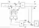
FIG. 1 shows a block diagram for carrying out the method, illustrating the controller architecture;
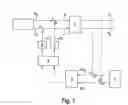
FIG. 2 shows a block diagram illustrating the control algorithm; and
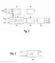
FIG. 3 shows a further block diagram illustrating the condition for carrying out and terminating the method for reducing the rollover risk.
DETAILED DESCRIPTION
FIG. 1 illustrates the controller architecture for carrying out the method for multicircuit control, having a first control loop which influences the yaw rate and a second control loop which influences the transverse acceleration. Block 1 represents the driver, who specifies a steering angle δF and a brake pressure pF. The specifications by the driver are in each case superimposed by superimposition values Δδ for the steering angle and Δp for the brake pressure, resulting in an overall steering angle δ and an overall brake pressure p which are in effect in the vehicle represented by block 2. A prerequisite is an actively adjustable steering system which permits generation of a superimposed steering angle. If such a system is not provided in the vehicle, instead of a superimposed steering angle the steering torque may also be influenced by the control system.
After the actuators in the steering system and in the braking system, and optionally an actuator to be associated with an active chassis system, have been activated, the instantaneous values of yaw rate {dot over (ψ)} and transverse acceleration ay are available to other control loops. In the present multivariable control for reducing the rollover risk of the vehicle, these actual values are also returned in a closed circuit. To this end, setpoint values which are ascertained in a block 3, which is a component of the regulation and control unit in which the method runs, are subtracted from the instantaneous values of yaw rate {dot over (ψ)} and transverse acceleration ay which are available at the output of block 2. Obtained as results are control deviations Δ{dot over (ψ)} for the yaw rate and Δay for the transverse acceleration, which are sent to a controller 4 which likewise is a component of the regulation and control unit. Actuating signals are generated via controller 4 and a block 5 downstream from the controller which is used as a coordination unit, and the actuating signals are sent to actuators 6 and 7 for the steering system and the braking system, respectively, and optionally to an actuator for the active chassis system. Superimposition values Δδ and Δp are generated in these actuators and, as described above, are superimposed on values δF and δp specified by the driver.
FIG. 2 illustrates the control algorithm for carrying out the multivariable control. In a block 8 a coefficient computation is carried out as a function of supplied actual values for vehicle velocity vx, transverse acceleration ay, yaw rate {dot over (ψ)}, and optionally other vehicle state variables. These coefficients are then transmitted to the control algorithms for the transverse acceleration control (block 10) and the yaw rate control (block 11), in which the adjustment variables are ascertained, taking into consideration control deviations Δay and Δ{dot over (ψ)}, and the adjustment variables are sent to subsequent coordination block 12 for distributing the control interventions to the steering system and the braking system. Via block 9, this coordination block 12 is also supplied with the instantaneous specifications by the driver.
On the output side, the signals from coordination block 12 are first converted in a downstream block 13, and then in the form of superimposition values Δδ and Δp are sent to the steering system or the braking system. As an example, an additional superimposition value Δx, which, for example, is to be sent to an active chassis system, is present at the output of block 13.
FIG. 3 illustrates a simple block diagram having a block 14 which represents the condition for carrying out and terminating the method. As a function of slip angle αf at the wheels on the front axle and αr at the wheels on the rear axle, a decision is made as to whether the vehicle is in a stable state, an unstable state, or a state approximating the unstable state. Depending on the magnitude of slip angle αf, αr, the method for the stabilizing multivariable control is either resumed or terminated. The conditions may also be formulated in such a way that various systems in the vehicle may be activated or remain uninfluenced in a hierarchical manner; for example, when there is increased rollover risk, initially only the steering system is acted on, and the braking system is additionally acted on only if the rollover risk further increases.
Claims
What is claimed is:1. A method for reducing a rollover risk in vehicles, comprising:
ascertaining at least one state variable which characterizes transverse dynamics of the vehicle;
performing an intervention, based on the at least one state variable, into a steering system and a braking system which stabilizes the vehicle;
performing a multivariable control, for stabilizing the vehicle, in which two control loops are superimposed, a first control loop being based on control of at least one of (a) a yaw rate and (b) a corresponding state variable, and second control loop being based on control of at least one of (a) a transverse acceleration and (b) a corresponding state variable; and
adjusting the steering system and the braking system via the first and second control loops.
2. The method according to claim 1, wherein the two control loops are based on a common setpoint reference value.
3. The method according to claim 2, wherein a transverse acceleration threshold value is specified as a setpoint value for the transverse acceleration control loop, and the transverse acceleration setpoint value is used to ascertain a yaw rate setpoint value for the yaw rate control loop.
4. The method according to claim 1, wherein sensor-determined state variables of an electronic stability program implemented in the vehicle are used.
5. The method according to claim 4, wherein the sensor-determined state variables include the yaw rate and the transverse acceleration.
6. The method according to claim 1, wherein data available in an electronic stability program is used to make a query as to whether there is a risk of the vehicle rolling over.
7. The method according to claim 1, wherein while the method is being carried out, the steering system is acted on permanently and the braking system is acted on as needed.
8. The method according to claim 7, wherein on the basis of a criterion which characterizes the stability of the vehicle, a decision is made as to whether the braking system is acted on or remains uninfluenced.
9. The method according to claim 8, wherein the criterion includes a slip angle.
10. The method according to claim 1, wherein a chassis actuator is acted on as needed.
11. The method according to claim 1, wherein an actively adjustable steering system is acted on, via which an additional steering angle, which is superimposed on the steering angle specified by a driver, is settable.
12. The method according to claim 11, wherein during the action on the steering system, additional interventions by other control systems into the steering system are suppressed.
13. The method according to claim 1, wherein an electrically actuatable steering system is acted on, via which an assisting steering torque is generatable.
14. A regulation and control unit, comprising:
an arrangement configured to perform a method for reducing a rollover risk in a vehicle, the arrangement including:
(a) an arrangement configured to ascertain at least one state variable which characterizes transverse dynamics of the vehicle;
(b) an arrangement configured to perform an intervention, based on the at least one state variable, into a steering system and a braking system which stabilizes the vehicle;
(c) an arrangement configured to perform a multivariable control, for stabilizing the vehicle, in which two control loops are superimposed, a first control loop being based on control of at least one of (a) a yaw rate and (b) a corresponding state variable, and second control loop being based on control of at least one of (a) a transverse acceleration and (b) a corresponding state variable; and
(d) an arrangement configured to adjust the steering system and the braking system via the first and second control loops.
15. A vehicle, comprising:
a regulation and control unit;
a steering system; and
a braking system;
wherein the regulation and control unit includes an arrangement configured to perform a method for reducing a rollover risk in the vehicle, the arrangement including:
(a) an arrangement configured to ascertain at least one state variable which characterizes transverse dynamics of the vehicle;
(b) an arrangement configured to perform an intervention, based on the at least one state variable, into the steering system and the braking system which stabilizes the vehicle;
(c) an arrangement configured to perform a multivariable control, for stabilizing the vehicle, in which two control loops are superimposed, a first control loop being based on control of at least one of (a) a yaw rate and (b) a corresponding state variable, and second control loop being based on control of at least one of (a) a transverse acceleration and (b) a corresponding state variable; and
(d) an arrangement configured to adjust the steering system and the braking system via the first and second control loops.
16. The vehicle according to claim 15, further comprising an actively adjustable chassis system.
Images & Drawings included:
Sources:
- United States Patent and Trademark Office - verify current appl. status at the USPTO↗
Similar patent applications:
Recent applications in this class:
- » 20250276682 2025-09-04
VEHICLE HAVING ADJUSTABLE SUSPENSION - » 20250222920 2025-07-10
INDEPENDENT CONTROL OF VEHICLE WHEELS - » 20250187588 2025-06-12
MOBILITY DEVICE - » 20250187587 2025-06-12
ARTIFICIALLY INTELLIGENT VEHICLE ROLLING RESISTENCE SYSTEM - » 20250178591 2025-06-05
COMPUTER SYSTEM AND COMPUTER-IMPLEMENTED METHOD - » 20250171012 2025-05-29
CONTROLLING VEHICLES BASED ON CURRENT MOTION CHARACTERISTICS - » 20250145149 2025-05-08
CONTROL SYSTEM FOR A VEHICLE - » 20250136088 2025-05-01
CONTROL SYSTEM FOR DETERMINING A REFERENCE SIDE AREA FOR A VEHICLE ENTITY - » 20250100543 2025-03-27
METHOD FOR DETERMINING A STEERING ROLL RADIUS, STEERING/BRAKING METHOD, CONTROLLER AND UTILITY VEHICLE - » 20250018927 2025-01-16
Vehicle Control Apparatus, Vehicle Control Method, and Vehicle Control System
Recent applications for this Assignee:
- » 20250154889 2025-05-15
PRESSURE CONTROL IN AN EXHAUST AFTERTREATMENT SYSTEM - » 20250154580 2025-05-15
ENZYME TRANSLOCATORS IN NANOGAP WITH 3' -ESTERS - » 20250147582 2025-05-08
METHOD FOR DETERMINING AN EYE DISTANCE IN A PAIR OF DATA GLASSES, AND DATA GLASSES - » 20250146568 2025-05-08
DRIVE ASSEMBLY AND VEHICLE HAVING SUCH A DRIVE ASSEMBLY - » 20250146495 2025-05-08
Flexible Pump Assembly for Use in a Fan Drive - » 20250140882 2025-05-01
FUEL CELL SYSTEM HAVING ENERGY RECUPERATION - » 20250137810 2025-05-01
METHOD FOR MATCHING A DIGITAL ROAD MAP - » 20250137033 2025-05-01
DNA UNFOLDING USING A FREE-END TAG FLOW MODIFIER - » 20250119751 2025-04-10
A BLUETOOTH COMMUNICATION METHOD AND SYSTEM - » 20250118116 2025-04-10
Diagnostic Protocol Search With Improved Efficiency