METHOD AND APPARATUS FOR OPERATING AT LEAST ONE CAMERA FROM A POSITION ESTIMATE OF A CONTAINER TO ESTIMATE ITS CONTAINER CODE
US20090109295A1
2009-04-30
12/262,114
2008-10-30
Abstract:
Methods and apparatus are disclosed that operate at least one camera configured to mount on a container handler by creating a position estimate of a container being handled by the container handler and controlling the camera with a directive in response to the position estimate, to generate a container image to estimate a container code of a container that is used to move cargo typically through container terminals.
Interested in similar patents?
Get notified when new applications in this technology area are published.
Classification:
G06Q10/087 » CPC main
Administration; Management; Logistics, e.g. warehousing, loading, distribution or shipping; Inventory or stock management, e.g. order filling, procurement or balancing against orders Inventory or stock management, e.g. order filling, procurement, balancing against orders
B65G1/137 » CPC further
Storing articles, individually or in orderly arrangement, in warehouses or magazines; Storage devices mechanical with arrangements or automatic control means for selecting which articles are to be removed
B66F9/0755 » CPC further
Devices for lifting or lowering bulky or heavy goods for loading or unloading purposes movable, with their loads, on wheels or the like, e.g. fork-lift trucks; Constructional features or details Position control; Position detectors
B66F9/186 » CPC further
Devices for lifting or lowering bulky or heavy goods for loading or unloading purposes movable, with their loads, on wheels or the like, e.g. fork-lift trucks; Constructional features or details; Platforms; Forks; Other load supporting or gripping members; Load gripping or retaining means Container lifting frames
G06Q10/08 » CPC further
Administration; Management Logistics, e.g. warehousing, loading, distribution or shipping; Inventory or stock management, e.g. order filling, procurement or balancing against orders
B65G63/004 » CPC further
Transferring or trans-shipping at storage areas, railway yards or harbours or in opening mining cuts ; Marshalling yard installations for articles for containers
B65G2203/041 » CPC further
Indexing code relating to control or detection of the articles or the load carriers during conveying; Detection means Camera
H04N5/232 IPC
Details of television systems; Studio circuitry; Studio devices; Studio equipment ; Cameras comprising an electronic image sensor, e.g. digital cameras, video cameras, TV cameras, video cameras, camcorders, webcams, camera modules for embedding in other devices, e.g. mobile phones, computers or vehicles; Television cameras ; Cameras comprising an electronic image sensor, e.g. digital cameras, video cameras, camcorders, webcams, camera modules specially adapted for being embedded in other devices, e.g. mobile phones, computers or vehicles Devices for controlling television cameras, e.g. remote control ; Control of cameras comprising an electronic image sensor
Description
CROSS REFERENCE TO RELATED APPLICATIONS
This patent application claims the benefit of Provisional Patent Application No. 60/983,888 filed Oct. 30, 2007, which is incorporated herein by reference.
TECHNICAL FIELD
This invention relates to operating at least one camera to create an image of a container by an apparatus on a container handler for use in estimating the container's code.
BACKGROUND OF THE INVENTION
Optical characteristic systems have been in use for several years in container shipping and storage yards, but have had some problems. The cameras have tended to be rigidly mounted to the container handlers and unresponsive to the actual position of the containers with respect to the cameras, which leads to the cameras being operated far more often than if the container's position was known and used. Methods and apparatus are needed to address this issue and take advantage of the opportunity that solving these problems provides.
SUMMARY OF THE INVENTION
At least one camera is configured to mount on a container handler, the camera is operated so that the camera is active only when a container being handled is in range to create the container images. Further, the camera may be operated so that the container can actively be found for image capture. A position estimate of the container is created and the camera controlled with at least one directive in response to the position estimate to create at least one container image used to create an estimate of the container code of the container.
The apparatus embodying the invention may include a first module generating the position estimate received by a second module to create directives for controlling the cameras. The first module may at least partly provide the means for creating the position estimate and the second module may at least partly provide the means for controlling at least one camera with at least one directive in response to the position estimate. The first module may further receive an estimate of the container size of the container further affecting the directives.
The first module may communicate with a handler interface to receive at least one of the following from sensors on or in the container handler: a sensed container presence, a sensed stack height, a container size estimate, a twistlock sensed state, a spreader sensed state, a sensed landing state, and/or a sensed hoist height.
The camera may be stationary or capable of directed movement. The camera may be operated by any combination of: initiating image capture, adjusting the focal length, altering the shutter speed, pivoting in one or two angular degrees of freedom, and/or positioning on a track. At least two cameras may preferably be operated with separate directives.
The second module may use at least one camera and lighting module containing the camera and a light source, possibly with light enabling and/or flash controls.
The optical characteristic system may or may not include the first module and/or the second module. The optical characteristic system may be configured to mount on the container handler, or be at a distance with a wireless transceiver employed to deliver the container images from the container handler to the optical characteristic system.
BRIEF DESCRIPTION OF THE DRAWINGS
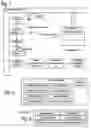
FIG. 1 shows an example of the apparatus and method operating at least one camera by creating a position estimate of a container being handled by a container handler and controlling the camera with a directive in response to the position estimate to create a container image used by an optical characteristic system to create an estimate of the container's code for further use by a container management system.
FIG. 2 shows some possible details of the position estimate of FIG. 1.
FIG. 3 shows some possible details of the directive for the camera of FIG. 1.
FIG. 4 shows a refinement of some aspects of FIG. 1 showing a second camera and a wireless transceiver for sending at least the container image to the optical characteristic system.
FIG. 5 shows a handler interface communicating with sensors on or in the container handler to aid in creating the position estimate by the first module of FIGS. 1 and 4.
FIGS. 6A and 6B show examples of the container of FIG. 1 and its container code.
FIG. 6C shows an example of a container code estimate of FIG. 6B's container code.
FIG. 7 shows an example of a stack of containers and a sensed stack height.
FIGS. 8A to 8D show examples of the use of the directives for the camera.
FIG. 9 shows an example of a camera and lighting module for use in or with the second module of FIGS. 1 and 4.
FIGS. 10A and 10B show the directive of the camera to position it on a track.
FIG. 11 shows various combinations of the first module and second module, possibly included in the optical characteristic system of FIGS. 1 and 4, possibly including at least one instance of at least one of a neural network, an inferential engine, a finite state machine and/or a computer instructed by a program system in a computer readable memory.
FIG. 12 shows a flowchart of the program system of FIG. 11 including two program steps, that may themselves be distinct program systems residing in separate computer readable memories in some embodiments of the invention.
FIG. 13 shows various combinations of the first module, second module and/or the optical characteristic system including the handler interface of FIG. 5 and/or including an interface to two instances of the camera and lighting module of FIG. 9 and/or including an enhanced container image.
FIG. 14 to 16 show flowcharts of some details of the first program system or program step of FIG. 12, creating the position estimate.
FIG. 17 shows a flowchart of some details of the second program system or program step of FIG. 12, controlling the camera with a directive in response to the position estimate.
And FIG. 18 shows a refinement of the program system of FIG. 12 to include using the enhanced container image of FIG. 13 to create the container code estimate.
DETAILED DESCRIPTION
This invention relates to operating at least one camera to create an image of a container by an apparatus on a container handler for use in estimating the container's code. Rather than over using at least one camera configured to mount on a container handler, the camera is operated so that the camera is active only when a container being handled is in focal range of the camera lens to create the container images. Further, the camera may be operated so that the container can actively be found by the camera for image capture. A position estimate of the container is created and the camera controlled with at least one directive in response to the position estimate to create at least one container image used to create an estimate of the container code of the container.
Referring to the drawings more particularly by reference numbers, FIG. 1 shows the operation of at least one camera 40 configured to mount on a container handler 2 by creating a position estimate 20 of the position 14 of a container 10 being handled by the container handler and controlling the camera with at least one directive 50 in response to the position estimate to create at least one container image 42. The container image is used to create a container code estimate 70 of the container code 12 of the container. The container code estimate may be generated by an optical characteristic system 60 and sent to a container management system 6 for a container facility, such as a terminal shipyard, a railway terminal, a container storage facility and/or a factory. The container position indicated by position estimate 20 may be based upon a position reference 18 that may or may not coincide with the location the camera.
The apparatus embodying the invention may include a first module 100 generating the position estimate 20 used by a second module 200 to create the directive 50 used by the camera 40. The first module may at least partly provide the means for creating the position estimate and the second module may at least partly provide the means for controlling at least one camera with at least one directive in response to the position estimate. The apparatus may further include at least one light source 4.
Note that in certain embodiments of the invention, the container images 42 may sometimes be unreadable by the optical characteristic system 60, whether or not mounted on the container handler 2. These container images may be sent to a second optical characteristic system that may use a human operator to determine the container code estimate 70 for the Container Management System 6.
FIG. 2 shows the position estimate 20 of FIG. 1 may include at least one of the following: a first angular estimate 22, a second angular estimate 24, a distance estimate 26, a height estimate 28, an X-axis estimate 30, a Y-axis estimate 32, a Z-axis estimate 34, and/or at least one fixed location estimates 36.
FIG. 3 shows some details of the directive 50 used to control one or more of the cameras 40 of FIG. 1, and may include at least one of the following: an image capture directive 51, a focal length 52, a shutter seed 53, a track position 54, a first angular directive 56, and/or a second angular directive 58.
The first module 100 may further receive an estimate of the container size 16 of the container 10, as shown in FIG. 1. By way of example, the container size may be a member of (but is not limited to) the container size group consisting of ten feet, twenty feet, twenty four feet, thirty three feet, forty five feet and fifty three feet.
The container handler 2 may include one or more of the following: a drayman truck, a UTR type truck, a bomb cart, a wheeled over the road chassis, a chassis rotator, a quay crane, a side picker, a top loader, a straddle carrier, a reach stacker and a Rubber Tire Gantry (RTG) crane. The invention includes specific embodiments suited for individual container handler collection, which will be discussed later. As used herein a drayman truck may be used to haul containers on chassis over open roads whereas a UTR type truck is restricted to operate in a container terminal such as a shipyard or rail yard.
Some embodiments of the invention send the container image 42 to the optical characteristic system 60 to create the container code estimate 70 as shown in FIGS. 1 and 4. The optical characteristic system may be configured to mount on the container handler 2, or be at a distance with a wireless transceiver 90 employed to deliver 92 the container images from the container handler to the optical characteristic system. The optical characteristic system may include the first module 100 and/or the second module 200 as shown in FIGS. 11 and 13.
FIG. 5 shows the first module 100 may communicate with a handler interface 140 to receive at least one of the following from the container handler 2:
-
- a presence sensor 102 may create a sensed container present 104, the sensed container present may be a form of “Yes” or “No”, or may further at least partly delineate the container size 16, and/or the landed sensed state 124 or twistlock sensed state 116 to determine container presence. Note that the sensed container present may further delineate presence of one or both of dual twenty foot containers in certain embodiments;
- a stack height sensor 106 may create a sensed stack height 108, the sensed stack height is shown in FIG. 7;
- a size sensor 110 may create a container size estimate 112 and/or a spreader sensor 118 may create a spreader sensed state 120, the container sensed size and/or the spreader sensed state may indicate the container size 16 of FIGS. 1 and 4;
- a twistlock sensor 114 may create a twistlock sensed state 116, the twistlock sensed state may be a form of “Yes” or “No” indicating whether the twistlock is engaged with the container 10 or not;
- a landing sensor 122 may create a sensed landing state 124, the landing state may be a form of “Yes” or “No”;
- a hoist sensor 126 may create a sensed hoist height 128, the sensed hoist height is shown in FIG. 4; and/or
- a weight sensor 130 may create a sensed container weight 132. Note that in some embodiments of the invention, the weight sensor may include a strain gauge and the sensed container weight may be measured in terms of a strain reading from the strain gauge.
FIGS. 6A and 6B show two examples of containers 10 and their container codes 12, the first written vertically and the second written horizontally. FIG. 6C shows a container code estimate 70 of a container code. Note that the container code estimate of FIG. 6C does not completely agree with the container code of FIG. 6B. Enhancing the container image 42 to create an enhanced container image 76 shown in FIG. 13 can reduce these discrepancies. This will be discussed with regards FIGS. 13, 17 and 18 hereafter.
FIG. 7 shows an example of a stack of containers 10 and the sensed stack height 108. In some environments, containers may be stacked higher than four containers, and as shown in this Figure, may typically be stacked up to seven containers high. Typically, containers range between eight and ten feet in height and usually between eight and a half feet and nine and a half feet in height.
FIGS. 8A to 8D show some examples of the directives 50 used to operate the camera 40. The camera may be operated by any combination of the following: a fixed camera for forty foot containers and a fixed camera for twenty foot containers, pivoting the camera in a first angular degree of freedom 202 by a first angular directive 56, pivoting the camera in a second angular degree of freedom 204 by a second angular directive 58, adjusting the focal length 206 to 208 of the camera.
FIG. 9 shows a camera and lighting module 230 that may be included in the second module 200. The camera and lighting module includes a camera 40 and a light source 4. The camera may be operating based upon one or more of the following:
-
- a first angular directive 52 stimulating a first pivot control 212 to pivot the camera in the first angular degree of freedom 202 as shown in FIGS. 8A to 8C;
- a second angular directive 54 stimulating a second pivot control 214 to pivot the camera in the second angular degree of freedom 204;
- a focal length 56 stimulating the focal length control 216 to alter the camera's focal length as shown in FIGS. 8A and 8D;
- a shutter speed 59 stimulating a shutter speed control 218; and
- an image capture directive 57 stimulating an image capture control 210.
The directives 50 may also enable a lighting directive 55 for stimulating a lighting control 220 trigger the light source either to strobe or to be steadily turned on. The light source may include flood lights, infra-red sources, arrays of Light Emitting Diodes (LEDs) and/or Xenon light sources.
The camera 40 may be positioned on a track 230 in response to the track position 54 at a first track position 234 as shown in FIG. 10A. FIG. 10B shows the camera on the track at a second track position 236. The track may include one rail as shown in FIG. 10B or more than one rail as shown in FIG. 10A.
FIG. 11 shows an optical characteristic system 60 for mounting on a container handler as previously shown and including the first module 100 and/or the second module 200. The optical characteristic system and/or the first module and/or the second module may include at least one instance of a neural network 70 and/or an inferential engine 72 and/or a finite state machine 74 and/or a computer 80 accessibly coupled 84 to a computer readable memory 82 and instructed by a program system 300 including program steps residing in the memory.
While there are numerous implementations of the optical characteristic system 60, the first module 100, and the second module 200, the Figures and discussion will focus on discussion the implementation of the invention's embodiments and methods in terms of discussing just one computer 80, and unless otherwise useful will refrain from going beyond summarizing salient details in the interests of clarifying this disclosure. However this effort to clarify the invention is not meant to limit the scope of the claims.
As used herein, a neural network 70 maintains a collection of neurons and a collection of synaptic connections between the neurons. Neural networks are stimulated at their neurons leading through their synaptic connections to the firing of other neurons. Examples of neural networks include but are not limited to aromatic chemical compound detectors used to detect the presence of bombs and drugs.
As used herein, an inferential engine 72 maintains a collection of inference rules and a fact database and responds to queries and assertions by invoking rules and accessing the fact database. Examples of inferential engines include fuzzy logic controllers and constraint based decision engines used to determine paths through networks based upon the network constraints, such as the current location of parked and moving vehicles and available storage locations for containers.
As used herein, a finite state machine 74 receives at least one input, maintains and updates at least one state and generates at least one output based upon the value of at least one of the inputs and/or the value of at least one of the states.
As used herein, a computer 80 includes at least one data processor and at least one instruction processor instructed by the program system 300, where each of the data processors is instructed by at least one of the instruction processors.
Some of the following figures show flowcharts of at least one embodiment of at least one of the methods of the invention, which may include arrows signifying a flow of control, and sometimes data, supporting various implementations.
The boxes denote steps or program steps of at least one of the invention's methods and may further denote at least one dominant response in a neural network 70, and/or at least one state transition of the finite state machine 74, and/or at least one inferential link in the inferential engine 72, and/or a program step, or operation, or program thread, executing upon the computer 80.
Each of these steps may at least partly support the operation to be performed as part of a means for an operation or use. Other circuitry such as network interfaces, radio transmitters, radio receivers, specialized encoders and/or decoders, sensors, memory management and so on may also be involved in performing the operation further providing the means for the operation.
The operation of starting in a flowchart is denoted by a rounded box with the word “Start” in it and may refer to at least one of the following: entering a subroutine or a macro instruction sequence in the computer 80, and/or of directing a state transition of the finite state machine 74, possibly pushing of a return state, and/or entering a deeper node of the inferential engine 72 and/or stimulating a list of neurons in the neural network 70.
The operation of termination in a flowchart is denoted by a rounded box with the word “Exit” in it and may refer to completion of those operations, which may result in at least one of the following: a return to dormancy of the firing of the neurons in the neural network 70, and/or traversal to a higher node in the inferential graph 72 of the fact database and/or the rules collection, and/or possibly return to a previously pushed state in the finite state machine 74, and/or in a subroutine return in the computer 80.
FIG. 12 shows a flowchart of the program system 300 of FIG. 11, including at least one of the following:
-
- program step 150 creates the position estimate 20 of the container 10, which may implement a first program system instructing a first computer in the first module 100; and
- program step 250 controls at least one camera 40 with the directive 50 in response to the position estimate, which may implement a second program system instructing a second computer in the second module 200.
FIG. 13 shows a refinement of various embodiments shown in FIG. 12, where the computer 80 is first communicatively coupled 142 to the handler interface 140, which may be preferred for the first module 100 whether or not included in the optical characteristic system 60. Also, the computer is second communicatively coupled 234, possibly through a camera interface 232 to a first and second camera and lighting modules, which may be preferred for the second module 200 whether or not included in the optical characteristic system. The computer is third communicatively coupled 94 to the wireless transceiver 90, which may be preferred for the second module, again whether or not included in the optical characteristic system.
At least one of the first 142, second 234 and third 94 communicative couplings may include a wireline communications protocol, which may further includes at least one of the following: a Synchronous Serial Interface protocol, an Ethernet protocol, a Serial Peripheral Interface protocol, an RS-232 protocol, and Inter-IC protocol (sometimes abbreviated as I2C), a Universal Serial Bus (USB) protocol, a Controller Area Network (CAN) protocol, a firewire protocol, which may include implementations of a version of the IEEE 1394 protocol, an RS-485 protocol and/or an RS-422 protocol.
The wireless transceiver 90 may include a radio frequency tag terminal and/or a radio frequency transmitter and receiver compliant with at least one wireless signaling convention that may implement at least one of a Time Division Multiple Access (TDMA) scheme, a Frequency Division Multiple Access (FDMA) scheme, and/or a spread spectrum scheme, such as:
-
- examples of the TDMA scheme may include the GSM access scheme;
- examples of the FDMA scheme may include the AMPs scheme;
- the spread spectrum scheme may use at least one of a Code Division Multiple Access (CDMA) scheme, a Frequency Hopping Multiple Access (FHMA) scheme, a Time Hopping Multiple Access (THMA) scheme and an Orthogonal Frequency Division Multiple Access (OFDM) scheme;
- examples of the CDMA scheme may include, but are not limited to, an IS-95 access scheme and/or a Wideband CDMA (W-CDMA) access scheme;
- examples of the OFDM scheme may include, but are not limited to, a version of the IEEE 802.11 access scheme; and
- another example of a spread spectrum scheme is the ANSI 371.1 scheme for radio frequency identification and/or location tags.
In certain embodiments, the first module 100 may use two position references 18 as shown in FIG. 1, one near the first camera and lighting module 230 and the second near the second camera and lighting module, calculating two position estimates to readily generate components to their directives 50, such as the first angular estimate 52 to be used as the first angular directive 56, and so on.
In various embodiments of the invention, the computer readable memory 82 may further include various combinations of some or all of the following: the position estimate 20, the container image 42, the second container image 46, a directive 50 preferably for the first camera and lighting module 230, a second directive preferably for the second camera and lighting module, an enhanced container image 76, and/or the container code estimate 72. The first and second container images may be created by the first camera and light module, and may be used to create the enhanced container image.
FIG. 14 shows some details of the first program system as the program step 150 of FIG. 12, and may include at least one of the following program steps:
-
- program step 152 senses the presence of the container 10 to create the sensed container presence 104, possibly through the handler interface 140 communicating with a presence sensor 102 on or in the container handler 2 as shown in FIG. 5;
- program step 154 senses the stack height of the container to create the sensed stack height 108, possibly through the handler interface communicating with the stack height sensor 106 or the sensed hoist height 128;
- program step 156 senses the size of the container to create the container size estimate 112, possibly through the handler interface communicating with the size sensor 110;
- program step 158 senses the twistlock state of the twistlock controlled by the container handler to create the twistlock sensed state 116, possibly through the handler interface communicating with the twistlock sensor 114. The twistlock state and its sensed state may preferably take values indicating “twistlock on” and “twistlock off”;
- program step 160 senses the spreader state of the spreader controlled by the container handler to create the spreader sensed state 120, possibly through the handler interface communicating with the spreader sensor 118. The spreader state and the spreader sensed state may indicate the container size 16 of FIGS. 1 and 4;
- program step 162 senses the landing state of the spreader on a container to create the sensed landing state 124, possibly through the handler interface communicating with the landing sensor 122. The landing state and sensed landing state may indicate “landed” and “not landed” in some form possibly further indicating if a spreader is “landed” on top of a container such that the twistlocks may be activated;
- program step 164 senses the height of the hoist controlled by the container handler to create the sensed hoist height 128, possibly through the handler interface communicating with the hoist sensor 126; and/or
- program step 165 senses the weight of the container to create the sensed container weight 132. Note that in some embodiments of the invention, a strain gauge may be used and the sensed container weight may be measured in terms of a strain reading from the strain gauge. Note that in some embodiments the hoist height and the stack height may be considered essentially the same. As used herein, the stack height refers to the number of containers (typically an assortment of 8.5 feet and 9.5 feet boxes) in a stack, whereas the hoist height refers to the actual distance from the hoist to the ground. In many situations, the stack height may be determined from hoist height 128.
FIG. 15 further shows some details of the first program system as the program step 150, and may further include program step 166 to create the position estimate 20 based upon at least one of the following: the sensed container presence 104, the sensed stack height 108, the container size estimate 112, the twistlock sensed state 116, the spreader sensed state 120, the sensed landing state 124, the sensed hoist height 128, and/or sensed container weight 132. Various individual and combinations of these sensed states may be used for instance to determine a fixed location, such as landing on the bed of the bomb cart 84.
FIG. 16 shows a further refinement of the first program step as the program step 150, and may include at least one of the following program steps:
-
- program step 168 calculates the first angular estimate 22 based upon the X-axis estimate 30, the Y-axis estimate 32, and/or the Z-axis estimate 34;
- program step 170 calculates the second angular estimate 24 based upon the X-axis estimate, the Y-axis estimate, and/or the Z-axis estimate;
- program step 172 calculates the distance estimate 26 based upon the X-axis estimate, the Y-axis estimate, and/or the Z-axis estimate;
- program step 174 calculates the focal length 52 based upon the distance estimate;
- program step 176 uses the fixed location estimate 36 to determine at least one of the X-axis estimate, the Y-axis estimate, the Z-axis estimate, the first angular estimate, the second angular estimate, the distance estimate, and/or the focal length;
FIG. 17 shows some details of the second program system as the program step 250, and may include at least one of the following program steps:
-
- program step 252 initiates the image capture 57 of the container image 40, possibly by using the image capture control 210; this program step may be used with fixed position cameras as well as cameras that may be positioned on a track or pivoted;
- program step 254 adjusts the camera based upon the focal length 52 as shown in FIGS. 8A and 8D and possibly using the focal length control 216;
- program step 256 fixes the shutter seed 53, possibly by using a shutter speed control 218;
- program step 258 powers at least one light source 4 based upon a lighting enable 55, possibly by using a lighting control 220;
- program step 260 pivots the camera 40 in a first angular degree of freedom 202 by a first angular directive 56 as shown in FIGS. 8A to 8C. The step may be implemented using the first pivot control 212 as shown in FIG. 9;
- program step 262 pivots the camera in a second angular degree of freedom 204 by a second angular directive 58, possibly using the second pivot control 214;
- program step 264 moves the camera on the track 230 of FIGS. 11A and 11B to a track position 54, possibly by using a track position control 232;
- program step 266 uses at least two container images, for example 40 and 46 as shown in FIGS. 4 and 13, to create an enhanced container image 76. By way of example, the two images may be used to remove motion induced blurring or noise in the enhanced image, or to increase contrast about the characters of the container code 12 as shown in FIGS. 6A and 6B, or to refine and/or infer the edges of the characters.
- Note that in some embodiments of the invention, the container images 42 may be compressed, possibly by the container handler 2, the first module 100, the second module 200, the optical characteristic system 60 and/or the container management system 6. Any or all of these apparatus components may store the container images as is or in a compressed format.
FIG. 18 shows some further details of the program system 300 of FIG. 12, including the program step 302 that uses the enhanced container image 76 to create the container code estimate 70.
The handler interface 140 may vary for different container handlers 2. For example when the container handler is a quay crane or an RTG crane, the container handler may include a Programmable Logic Controller (PLC) Interface coupled via a wireline protocol to position estimate 20 to get crane spreader interface status and position, and may further, possibly separately couple sensors to a crane hoist and trolley drum for estimates of the spreader vertical and horizontal position relative to dock and/or a sensor for determining the hoist and trolley position, for instance by using a tachometer signal from the trolley and hoist motors, proximity switches, optical encoders, or a laser beam. Also, the handler interface may include a wireline network interface to at least one of the sensors of the container handler. Any of these interface approaches may provide sensor reading of a hoist or trolley position. As used herein, a wireline network interface may implement an interface to at least one of the wireline communications protocols mentioned previously. Additional sensors of the RTG and Quay Crane may require the sensing of the hoist position (the vertical height) by coupling to the hoist drum with a tachometer sensor, proximity, or optical sensors, and/or digital encoders.
Another example, when the container handler 2 is a side picker, a top loader (also referred to as a top handler), a straddle carrier or a reach stacker, the handler interface 140 may include a wireline network interface to at least one of the sensors of the container handler. Other sensors may be accessible to the handler interface through separate wireline network interfaces and/or wireline network couplings.
A third example, when the container handler 2 is a UTR type truck or a bomb cart, the handler interface 140 may include a wireline network interface to at least one, and possibly all the accessed sensors of the container handler. Alternatively, more than one wireline network interfaces and/or wireline network couplings may be used.
The handler interface 140 may further receive any or all of the following information that may be forwarded to the container management system 6: the location of the container 10, a sensed operator identity of the operator operating the container handler 2, a container radio frequency tag, a container weight, a container damage estimate, an indication of the container handler moving in a reverse motion, a frequent stops count, a fuel level estimate, a compass reading, a collision state, a wind speed estimate, a vehicle speed, and an estimate of the state of a vehicle braking system. The location of the container may be in terms of a three dimensional location and/or a stack or tier location.
The handler interface 140 may include a second radio transceiver providing a radio frequency tag interface capable of locating the container handler 2 and/or identifying the container 10 and/or its container code 12.
The handler interface 140 may include a third radio transceiver using a Global Positioning System and/or a Differential Global Position System to determine the location of the container 2. In certain preferred embodiments, two transceivers may be employed, one for transmitting the optical characteristics and container images, and the other for monitoring and controlling system's powering up and powering down processes.
The handler interface 140 may include an interface to a short range and/or low power sonar, radar, or laser that may provide a position estimate 20 of the container 10. The radar may preferably be non-toxic for humans and possibly livestock and other animals in or near the containers.
The preceding embodiments provide examples of the invention, and are not meant to constrain the scope of the following claims.
Claims
What is claimed is:1. An apparatus configured to operate at least one camera configured to mount on a container handler, comprising:
said first module configured to create a position estimate of a container handled by said container handler; and
a second module configured to control said camera with at least one directive in response to said position estimate to create a container image of said container, whereby
said container image is used to estimate a container code of said container.
2. The apparatus of claim 1, wherein said position estimate includes at least one member of the collection comprising:
a first angular estimate,
a second angular estimate,
a distance estimate,
a height estimate,
an X-axis estimate,
a Y-axis estimate,
a Z-axis estimate, and
a fixed location estimate.
3. The apparatus of claim 1, wherein said first module comprises a handler interface to at least one of:
a presence sensor configured to respond to said container to create a sensed container present;
a stack height sensor configured to respond to a stack height of said container to create a sensed stack height;
a size sensor configured to respond to a size of said container to create a container size estimate;
a twistlock sensor configured to respond to a twistlock state of a twistlock controlled by said container handler to create a twistlock sensed state;
a spreader sensor configured to respond to a spreader state of a spreader controlled by said container handler to create a spreader sensed state;
a landing sensor configured to respond to a landing state of said container to create a sensed landing state;
a hoist sensor configured to respond to a height of a hoist controlled by said container handler to create a sensed hoist height; and
wherein said first module generates said position estimate based upon at least one member of a position-related-estimate group consisting of: said sensed container present, said sensed stack height, said container size estimate, said twistlock sensed state, said spreader sensed state, said sensed landing state, and said sensed hoist height.
4. The apparatus of claim 1, wherein said second module comprises at least one of:
an image capture control configured to initiate image capture by said camera in response to an image capture directive;
a focal length control configured to adjust said camera in response to a focal length;
a shutter speed control configured to alter said camera in response to a shutter speed;
a first pivot control configured to pivot said camera in a first angular degree of freedom in response to a first angular directive;
a second pivot control configured to pivot said camera in a second angular degree of freedom in response to a second angular directive; and
a track control configured to adjust a position of said camera on a track in response to a track position.
5. The apparatus of claim 1,
wherein at least one member of a module collection includes at least one instance of at least one member of the group consisting of:
a neural network,
an inferential engine,
a finite state machine, and
a computer accessibly coupled to a computer readable memory, said computer instructed by a program system including at least one program step residing in said computer readable memory;
wherein said module collection includes as members said first module and said second module.
6. The apparatus of claim 5, wherein said program system includes at least one the program steps of:
creating said position estimate of said container handled by said container handler; and
directing said at least one camera to create said container image of said container in response to said position estimate.
7. The apparatus of claim 5, wherein the program step creating said position estimate comprises at least one of the program steps of:
calculating a first angular estimate based upon an X-axis estimate, a Y-axis estimate, and a Z-axis estimate;
calculating a second angular estimate based upon said X-axis estimate, said Y-axis estimate, and said Z-axis estimate;
calculating a distance estimate based upon said X-axis estimate, said Y-axis estimate, and said Z-axis estimate;
calculating a focal length based upon said distance estimate; and
using a fixed location estimate to determine at least one of said first angular estimate, said second angular estimate, said distance estimate, and said focal length.
8. The apparatus of claim 5, wherein at least one member of a module collection is separate from said optical characteristic apparatus, wherein said module collection includes as members said first module and said second module.
9. The apparatus of claim 5, wherein at least one member of a module collection is included in said optical characteristic apparatus, wherein said module collection includes as members said first module and said second module.
10. The apparatus of claim 1, wherein said container handler includes at least one member of the group consisting of: a UTR type truck, a drayman truck, a bomb cart, an over the road chassis, a chassis rotator, a quay crane, a side picker, a top loader, a straddle carrier, a reach stacker, and a rubber tire gantry crane.
11. The apparatus of claim 1, wherein said container is a member of the group consisting of a ten foot container, a twenty foot container, a twenty four foot container, a thirty three foot container, a forty foot container, a forty five foot container, a fifty three foot container, and dual twenty foot containers.
12. An apparatus configured to operate at least one camera configured to mount on a container handler, comprising
means for creating a position estimate of a container handled by said container handler; and
means for controlling at least one camera with at least one directive in response to said position estimate to create a container image of said container, whereby said container image is used to create to estimate a container code of said container.
13. The apparatus of claim 12, wherein the means for creating said position estimate comprises at least one of:
means for sensing a presence of said container to create a sensed container present;
means for sensing a stack height of said container to create a sensed stack height;
means for sensing a size of said container to create a container size estimate;
means for sensing a twistlock state of a twistlock controlled by said container handler to create a twistlock sensed state;
means for sensing a spreader state of a spreader controlled by said container handler to create a spreader sensed state;
means for sensing a landing state of said container to create a sensed landing state;
means for sensing a height of a hoist controlled by said container handler to create a sensed hoist height; and
wherein the means for creating said position estimate further comprises:
means for estimating said position estimate based upon at least one member of a position-related-estimate group consisting of: said sensed container present, said sensed stack height, said container size estimate, said twistlock sensed state, said spreader sensed state, said sensed landing state, and said sensed hoist height.
14. The apparatus of claim 12, wherein the means for directing said at least one camera comprises at least one of:
means for adjusting a focal length of said camera based upon a distance estimate;
means for fixing a shutter speed of said camera;
means for moving said camera on a track to a track position;
means for pivoting said camera in a first angular degree of freedom by a first angular estimate; and
means for pivoting said camera in a second angular degree of freedom by a second angular estimate.
15. The apparatus of claim 12,
wherein at least one member of a means collection includes at least one instance of at least one member of the group consisting of:
a neural network,
an inferential engine,
a finite state machine, and
a computer accessibly coupled to a computer readable memory, said computer instructed by a program system including at least one program step residing in said computer readable memory;
wherein said means collection includes as members said means for creating and said means for directing.
16. A method, comprising the step of:
operating at least one camera configured to mount on a container handler, comprising the steps of:
creating a position estimate of a container being handled by said container handler; and
controlling said camera with at least one directive in response to said position estimate to create a container image of said container, whereby said container image is used to estimate a container code of said container.
17. The method of claim 16, wherein the step of creating said position estimate comprises at least one of the steps of:
sensing a presence of said container to create a sensed container present;
sensing a stack height of said container to create a sensed stack height;
sensing a size of said container to create a container size estimate;
sensing a twistlock state of a twistlock controlled by said container handler to create a twistlock sensed state;
sensing a spreader state of a spreader controlled by said container handler to create a spreader sensed state;
sensing a landing state of said container to create a sensed landing state; and
sensing a height of a hoist controlled by said container handler to create a sensed hoist height; and
wherein the step of creating said position estimate further comprises the step of:
estimating said position estimate based upon at least one member of a group consisting of: said sensed container present, said sensed stack height, said container size estimate, said twistlock sensed state, said spreader sensed state, said sensed landing state, and said sensed hoist height.
18. The method of claim 16, wherein the step controlling said at least one camera, comprises at least one of the steps of:
adjusting a focal length of said camera;
fixing a shutter speed of said camera;
moving said camera on a track to a track position;
pivoting said camera in a first angular degree of freedom by a first angular directive; and
pivoting said camera in a second angular degree of freedom by a second angular directive.
19. The method of claim 16, further comprising the step of: using an enhanced image to create said container code estimate, said enhanced image created by using at least two of said container images.
20. The method of claim 16, wherein said container handler includes at least one member of the group consisting of: a Draymen truck, UTR type truck, a bomb cart, a chassis rotator, an over the road chassis, a quay crane, a side picker, a top loader, a straddle carrier, a reach stacker, and a rubber tire gantry crane.
21. A first program system of program steps residing in a computer readable memory, said first program system comprising the program step of:
creating a position estimate of a container handled by a container handler for use in directing at least one camera mounted on said container handler to create a container image used to estimate a container code of said container.
22. A second program system of program steps residing in a computer readable memory, said second program system comprising the program step of:
controlling at least one camera with at least one directive in response to a position estimate of a container being handled by a container handler to create a container image, whereby
said camera is configured to mount on said container handler,
said container image is used to estimate a container code of said container.
Images & Drawings included:


Sources:
- United States Patent and Trademark Office - verify current appl. status at the USPTO↗
Recent applications in this class:
- » 20250173675 2025-05-29
SUGGESTING A RECIPE TO A CUSTOMER OF AN ONLINE CONCIERGE SYSTEM BASED ON ITEMS LIKELY TO BE AVAILABLE - » 20250173674 2025-05-29
DELIVERY SYSTEM - » 20250173673 2025-05-29
SUPPLY AND INVENTORY PREDICTIONS IN SUPPLY CHAIN NETWORKS - » 20250173672 2025-05-29
SIMULATION SERVICE MODEL FOR INVENTORY OPTIMIZATION - » 20250173671 2025-05-29
ARTIFICIAL INTELLIGENCE WAREHOUSE MANAGEMENT TRANSSHIPMENT SYSTEM - » 20250173670 2025-05-29
TECHNIQUES FOR PASSIVE DETECTION OF A STOCK ITEM USING A LOW ENERGY WIRELESS TAG AND REAL-TIME FEEDBACK - » 20250173669 2025-05-29
LOGICAL COMPOSITE DEVICES IN COMMUNICATION NETWORK INVENTORIES - » 20250165921 2025-05-22
MEDICAL CABINET COMMUNICATION SYSTEM AND METHODS - » 20250165920 2025-05-22
SYSTEMS AND METHODS FOR ADDRESSING CROSS-PEGGING IN A MULTI-LEVEL SEARCH - » 20250165919 2025-05-22
DYNAMIC INVENTORY TRACKING AND DISPENSING SYSTEM