SHOE
US20090288315A1
2009-11-26
12/467,294
2009-05-17
Abstract:
An exemplary shoe includes a upper, a sole, an LED (light-emitting diode) and a power supply device. The upper is disposed on the sole. The sole includes a receiving space. The LED is installed on an outside surface of the sole. The power supply module is for providing electric power to the light emitting diode. The power supply module further includes a piezoelectric member coupled to the sole and a electric power storing device. The piezoelectric member is disposed between the upper and the sole. The electric power storing device is received in the receiving space of the sole and electrically coupled between the piezoelectric member and the light emitting diode.
Assignee:
- HON HAI PRECISION INDUSTRY CO., LTD. 12,828 🇹🇼 Tu-Cheng, Taiwan
Interested in similar patents?
Get notified when new applications in this technology area are published.
Classification:
A43B1/0036 » CPC further
Footwear characterised by the material made at least partially from a material having special colours with fluorescent or phosphorescent parts
A43B13/00 IPC
Parts of footwear
A43B13/00 IPC
Soles; Sole-and-heel integral units
A43B23/00 IPC
Uppers; Boot legs; Stiffeners; Other single parts of footwear
Description
BACKGROUND
1. Technical Field
The present disclosure generally relates to shoes, particularly, to a shoe with light emitting diodes.
2. Discussion of Related Art
Nowadays, various type of shoes may include light emitting diodes embedded for aesthetic or safety reasons. The light emitting diodes are usually powered by battery. However, the electric power of the battery will easily run out overtime and the old battery must be replaced by new ones. Therefore, such shoes are not environmentally friendly.
Therefore, what is needed is a shoe that overcomes the described limitations.
BRIEF DESCRIPTION OF THE DRAWINGS
Many aspects of the disclosed shoe can be better understood with reference to the following drawings. The components in the drawings are not necessarily drawn to scale, the emphasis instead being placed upon clearly illustrating the principles of the present shoe, wherein:
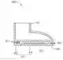
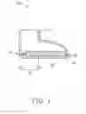
FIG. 1 is a cross-sectional view of a shoe, according to an exemplary embodiment; and
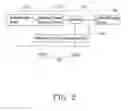
FIG. 2 is a block diagram showing a power supply module of the shoe in FIG. 1.
DETAILED DESCRIPTION
Reference will now be made to the drawings to describe the embodiments of the shoe, in detail.
Referring to FIG. 1, a shoe 100, according to a first embodiment, includes a upper 10, a sole 20, a light emitting diode (LED) 40 and a power supply module 60.
The upper 10 is disposed on the sole 20.
The sole 20 includes an internal receiving space 22. In an exemplary embodiment, the receiving space 22 is defined between the upper 10 and the sole 20 and communicates with a surface of the upper 10. The receiving space 22 can also be defined in an interior of the sole 20 without communicating with any surface of the upper 10.
The LED 40 is installed on an outside surface of the sole 20. In an exemplary embodiment, the LED 40 is installed on a front outside surface of the sole 20, thereby illuminating the area in front of the shoe.
The power supply module 60 is configured for providing electric power to the LED 40. The power supply module 60 includes a piezoelectric member 62 coupled to the sole 20 and an electric power storing device 64. In an exemplary embodiment, the sole 20 has a heel portion 21 and the piezoelectric member 62 is embedded in the heel portion 21.
The piezoelectric member 62 is disposed between the upper 10 and the sole 20. The piezoelectric member 62 can be made of barium titanate (BaTiO3), lithium germanium oxide (LiGeO3) or polyvinylidene fluoride (PVDF). When the shoe 100 is in motion (i.e. walking, running, etc), pressures generated by motion will be applied to the piezoelectric member 62. Then, the piezoelectric member 62 will transform the mechanical energy into electric energy and thereby electric power is generated by the piezoelectric member 62. The piezoelectric member 62 will transmit the electric power to the power storing device 64.
The electric power storing device 64 is received in the receiving space 22 and electrically coupled between the piezoelectric member 62 and the light emitting diode 40. The electric power storing device 64 can be a capacitor, or a rechargeable battery, or other electrical components capable of storing electric power. The electric power storing device 64 is capable of receiving the electric energy transmitted from the piezoelectric member 62 and thereby providing electric power to the LED 40.
In an exemplary embodiment, a switch 66 is coupled between the electric power storing device 64 and the LED 40. The switch 66 has two status of close and open. Thereby, the switch 66 is capable of being used to control the electric power stored in the electric power storing device 64 whether to be supplied to the LED 40.
In an exemplary embodiment, the power supply module 60 further comprises a detecting device 68. The detecting device 68 has a predetermined standard brightness value stored therein. The detecting device 68 is configured for detecting a brightness of the exterior environment, comparing the detected brightness with the predetermined standard brightness, and controlling the switch 66 to open or close according to the comparison result.
On the condition that the brightness value of the exterior environment is lower than the predetermined brightness value, the detecting device 68 controls the switch 66 to open to provide electric power to the LED 40. On the condition that the brightness value of the exterior environment is higher than the predetermined brightness value, the detecting device 68 controls the switch 66 to close to cut off the electric power transmitted to the LED 40.
In a further exemplary embodiment, the detecting device 68 includes a sensing cell 68a and a comparing cell 68b. The sensing cell 68a is configured for sensing the brightness of the exterior environment. The sensing cell 68a can be a photodiode, or a photometer, or other components capable of sensing light brightness. The comparing cell 68b has the predetermined standard brightness value stored therein. The comparing cell 68b is configured for comparing the detected brightness with the predetermined standard brightness thereby controlling the switch to open or close on the condition that the exterior environment is lower or higher than the predetermined brightness value.
It is to be said that, the switch 66 can be disposed on an outer surface of the sole 20. Thereby, the switch 66 can be artificially closed or open without depending on the comparison result of the detecting device 68.
Due to that the shoe 100 are equipped with the piezoelectric member 62 and the electric power storing device 64, mechanical energy generated motions of the shoe 100 can be transformed into electric energy by the piezoelectric member 62, and the transformed electric energy can be stored and transmitted to the LED 40 for use by the electric power storing device 64. Thereby, the shoe 100 is energy-saving and environmentally friendly.
Finally, it is to be understood that the above-described embodiments are intended to illustrate rather than limit the disclosure. Variations may be made to the embodiments without departing from the spirit of the disclosure as claimed. The above-described embodiment illustrates the scope of the disclosure but do not restrict the scope of the disclosure.
Claims
What is claimed is:1. A shoe, comprising:
a sole;
an upper disposed on the sole;
a light emitting diode installed on an outside surface of the sole;
a power supply module for providing electric power to the light emitting diode, the power supply module comprising a piezoelectric member coupled to the sole and an electric power storing device, the piezoelectric member being configured for generating electric power, the electric power storing device being electrically coupled between the piezoelectric member and the light emitting diode.
2. The shoe according to claim 1, wherein the light emitting diode is installed on a front outside surface of the sole.
3. The shoe according to claim 1, wherein the electric power storing device comprises a capacitor or a rechargeable battery.
4. The shoe according to claim 1, wherein the power supply module further comprises a switch electrically coupled between the electric power storing device and the light emitting diode.
5. The shoe according to claim 4, wherein the power supply module further comprises a detecting device, the detecting device having a predetermined standard brightness value stored therein, the detecting device being configured for sensing a brightness of the exterior environment and comparing the detected brightness with the predetermined standard brightness, and controlling the switch to open or close according to the comparison result.
6. The shoe according to claim 5, wherein the detecting device further comprises a sensing cell and a comparing cell, the sensing cell being configured for sensing the brightness of the exterior environment, the comparing cell being configured for comparing the detected brightness with the predetermined standard brightness thereby controlling the switch to open or close according to the comparison result.
7. The shoe according to claim 1, wherein the piezoelectric member is made of a material selected from a group consisting of barium titanate, lithium germanium oxide and polyvinylidene fluoride.
8. A shoe comprising:
a sole having a heel portion;
an upper attached on the sole;
a light emitting member;
a piezoelectric member embedded in the heel portion for generating electric power, and
an electric power storing device configured for storing the electric power and being electrically coupled between the piezoelectric member and the light emitting member.
Images & Drawings included:
Sources:
- United States Patent and Trademark Office - verify current appl. status at the USPTO↗
Similar patent applications:
- » 20190070529
Filling shoe, a filling shoe arrangement having such a filling shoe, a filter medium assembly having such filling shoe arrangements, and a method for providing a filter medium with such a filling shoe - » 20190328085
Method for fastening a shoe, in particular, a sports shoe, and shoe, in particular sports shoe - » 20140230278
Ankle Flexi System for Soccer shoes, Football shoes, Baseball Shoes, Speed skates skateboard, Ice skates and Hockey shoes. - » 20060201011
Foot tilt angle measuring method, method of selecting shoe or insole for shoe method of manufacturing shoe or insole for shoe, and foot unit tilt angle measuring device - » 20070056189
Ankle protection system for soccer shoes, football shoes, baseball shoes, speed skates skateboard and ice skates shoes - » 20190327950
ANIMAL SHOE, IN PARTICULAR AN ORTHOPEDIC SHOE FOR ANIMAL FEET FOR THE RELIEF OF LAME CLOVEN-HOOFED ANIMALS, AND SHOE BASE AND KIT FOR SUCH AN ANIMAL SHOE - » 20170006962
Shoe sole, insole of shoe, main sole of shoe, and shoe - » 20150013194
Shoe sole, shoe with such a shoe sole and method for the production of such a shoe sole - » 20190082787
Shoe sole, insole of shoe, main sole of shoe, and shoe - » 20220333305
METHOD FOR OPERATING A SHOE PRESS, SHOE PRESS, MACHINE COMPRISING A SHOE PRESS, AND USE OF AN INK IN A LUBRICANT FOR A SHOE PRESS
Recent applications in this class:
- » 20230148701 2023-05-18
Wireless charging assemblies for sensorized insoles, methods for charging sensorized insoles, and footwear systems including sensorized insoles - » 20230000200 2023-01-05
Dubui-shoe (assistance free footwear for disabled) - » 20220408872 2022-12-29
Insole with embedded sensing system - » 20220142290 2022-05-12
Gait correction treadmill and footwear system - » 20220053874 2022-02-24
Article of footwear and charging system - » 20220053873 2022-02-24
Automated tensioning system for an article of footwear - » 20220053872 2022-02-24
Insole-type electronic device and control method for insole-type electronic device - » 20220031007 2022-02-03
Article of footwear with color change portion and method of changing color - » 20220022590 2022-01-27
Customizable Footwear - » 20220015496 2022-01-20
Motorized shoe with gesture control
Recent applications for this Assignee:
- » 20140233961 2014-08-21
Optical communication module including optical-electrical signal converters and optical signal generators - » 20140083669 2014-03-27
HEAT SINK - » 20140063746 2014-03-06
Electronic device with heat dissipation assembly - » 20140061224 2014-03-06
AUTOMATIC VENDING MACHINE - » 20140060914 2014-03-06
Enclosure with shield apparatus - » 20140058727 2014-02-27
MULTIMEDIA RECORDING SYSTEM AND METHOD - » 20140055955 2014-02-27
Fastener - » 20140055322 2014-02-27
DISPLAY SYSTEM AND HEAD-MOUNTED DISPLAY APPARATUS - » 20140054439 2014-02-27
CONTAINER DATA CENTER WITH SUPPORTING APPARATUS - » 20140054311 2014-02-27
AUTOMATIC VENDING MACHINE WITH MOVING MEMBER FOR PRODUCTS