COMPUTER PARTS ORGANIZER AND ASSEMBLY TRAY FOR ASSEMBLING A COMPUTER
US20090288979A1
2009-11-26
12/346,872
2008-12-31
Abstract:
A computer parts organizer organizes various computer parts according to size and quantities of the computer parts. The computer parts organizer is divided into various compartments by one or more removable isolation boards. The computer parts organizer can be attached to an assembly tray via a clip.
Assignee:
- HON HAI PRECISION INDUSTRY CO., LTD. 12,828 🇹🇼 Tu-Cheng, Taiwan
- HONG FU JIN PRECISION INDUSTRY (SHENZHEN) CO., LTD. 4,225 🇨🇳 Shenzhen City, China
Interested in similar patents?
Get notified when new applications in this technology area are published.
Classification:
G06F1/18 » CPC main
Details not covered by groups - and; Constructional details or arrangements Packaging or power distribution
B65D1/34 IPC
Containers having bodies formed in one piece, e.g. by casting metallic material, by moulding plastics, by blowing vitreous material, by throwing ceramic material, by moulding pulped fibrous material, by deep-drawing operations performed on sheet material Trays or like shallow containers
Description
BACKGROUND
1. Technical Field
Embodiments of the present disclosure relate to computer production, and particularly to a computer parts organizer, and assembly tray for assembling a computer.
2. Description of Related Art
At present, a computer is assembled step by step at several workstations of an assembly line, and parts to be assembly at each workstation are stored at a feed preparation area near each workstation (refer to FIG. 1).
However, large numbers of parts occupy much space on the assembly line. Thus, it is inconvenient for workers to feed and assemble the parts. Additionally, the user may make mistakes due to the crowded conditions. For example, in FIG. 1, workstations 6, 7 are each data bus stations, but one data bus station is for an optical drive of the computer and the other data bus station is for a hard drive of the computer. Although there is a difference in the data buses used at the stations, it is easy for an assembler to grab the wrong one.
What is needed, therefore, is a system and method for assembling a computer with high efficiency.
BRIEF DESCRIPTION OF THE DRAWINGS
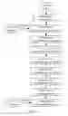
FIG. 1 is a flowchart of a prior art of a method for assembling a computer;
FIG. 2 is a schematic diagram of one embodiment of a computer parts organizer for use with assembly of a computer of an exemplary embodiment;
FIG. 3 is a schematic diagram of one embodiment of an assembly tray for use with the computer parts organizer shown in FIG. 2; and
FIG. 4 is a flowchart of one embodiment of a method for assembling a computer using the computer parts organizer shown in FIG. 2.
DETAILED DESCRIPTION OF CERTAIN INVENTIVE EMBODIMENTS
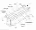
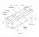
FIG. 2 is a schematic diagram of one embodiment of a computer parts organizer 2 (hereinafter, “the parts organizer 2”) used for assembling a computer. In one embodiment, the parts organizer 2 includes one or more separated compartments 21. In one embodiment, a clip 22 may be installed on a lower part of a sidewall of the parts organizer 2. The sidewall has the longest edge of the parts organizer 2. The clip 22 may be installed with a bumper 23 on. The top corners of the parts organizer 2 are installed with a riveted framework 24 thereon. In other embodiments, additional or different kinds of clips may be used.
The compartments 21 may be configured for storing different size parts. In this embodiment, the parts may include a motherboard, a CPU heat sink, a graphics card, an optical drive, a hard disk, and data buses for the optical drive and the hard disk. The compartments 21 of the parts organizer 2 may be separated by one or more removable isolation boards. It may be understood that quantities or sizes of the compartments 21 are variable by adjusting the removable isolation boards based on varieties or sizes of parts to be stored, in order that each compartment stores one kind of part.
The clip 22 connects the parts organizer 2 with an assembly tray 1 (refer to FIG. 3). The bumper 23 is used for absorbing shock if there is a collision between the parts organizer 2 and other objects (e.g. a chassis to be assembled). In one embodiment, the bumper 23 may be made from an elastic material, such as a foam. The riveted framework 24 is used for fixing/supporting the stacking of more than one parts organizer 2.
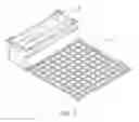
FIG. 3 is a schematic diagram of one embodiment of the assembly tray 1 used cooperatively with the parts organizer 2 shown in FIG. 2. In one embodiment, the surface of the assembly tray 1 may be divided into square grids, so as to improve a mechanical strength of the assembly tray 1. To prevent static electricity, the surface of the assembly tray 1 may be covered with an anti-static material. The assembly tray 1 is connected with the parts organizer 2 by the clip 22.
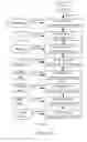
FIG. 4 is a flowchart of one embodiment of a method for assembling a computer using the parts organizer 2 shown in FIG. 2. At workstation 1: The user places a chassis to be assembled on the assembly tray 1, puts each of the parts with large sizes into a corresponding compartment 21 of the parts organizer 2, in order that each compartment 21 stores one kind of part, and fixes the parts organizer 2 on the assembly tray 1, then the procedure goes to the next workstation. In one embodiment, the parts with large sizes include: a motherboard, a CPU heat sink, a graphics card, an optical drive, a hard disk, and data buses for the optical drive and the hard disk. The data bus for the optical device and the data bus for the hard disk are marked with different colors. For example, a color of the data bus for the optical device is green, and a color of the data bus for the hard disk is red. In one embodiment, the workstation 1 is near to a part issuing warehouse storing the parts with large sizes so as to prepare all the parts with large sizes to be assembled.
At workstation 2: The user fetches a CPU and a memory from a feed preparation area near the workstation 2, and installs the CPU and the memory on the motherboard placed in the compartment 21 of the parts organizer 2. Because the CPU and memory are expensive and easy to be damaged, these kind of parts (i.e., expensive and easy to be damaged) would better stored at a special feed preparation area near the workstation.
At workstation 3: The user installs the motherboard on the chassis if the CPU and the memory have been installed on the motherboard.
At workstation 4: The user fetches the CPU heat sink from the compartment 21 of the parts organizer 2, and installs the CPU heat sink on the chassis.
At workstation 5: The user fetches the graphics card from the compartment 21 of the parts organizer 2, and installs the graphics card on the chassis.
At workstation 6: The user fetches the optical drive from the compartment 21 of the parts organizer 2, and installs the optical drive on the chassis.
At workstation 7: The user fetches the hard disk from the compartment 21 of the parts organizer 2, and installs the hard disk on the chassis.
At workstation 8: The user fetches the data buses for the optical drive and the hard disk from the compartment 21 of the parts organizer 2, and installs the data bus on the chassis.
At workstation 9: The user fetches side covers from a feed preparation area near the workstation 9 if there is no part in the compartment 21 of the parts organizer 2, and installs the side covers on the chassis thereby obtaining an assembled computer.
The kinds of the large parts stored in the compartments 21 of the parts organizer 2 are variable according to a type of the computer to be assembly, the quantities and the sizes of the compartments 21 of the parts organizer 2 are variable according to the kind of the large parts.
In other embodiments, the assembly sequences from workstation 4 to workstation 7 are variable according to the type of the computer to be assembled.
It should be emphasized that the above-described embodiments of the present disclosure, particularly, any embodiments, are merely possible examples of implementations, merely set forth for a clear understanding of the principles of the disclosure. Many variations and modifications may be made to the above-described embodiment(s) of the disclosure without departing substantially from the spirit and principles of the disclosure. All such modifications and variations are intended to be included herein within the scope of this disclosure and the present disclosure and protected by the following claims.
Claims
What is claimed is:1. A computer parts organizer for storing computer parts, the computer parts organizer comprising one or more separated compartments, a clip being installed on a lower part of a sidewall of the parts organizer, the sidewall having the longest edge of the parts organizer;
wherein the compartments of the computer parts organizer are separated by one or more removable isolation boards, wherein quantities or sizes of the compartments are variable by adjusting the removable isolation boards based on varieties or sizes of the computer parts to be stored.
2. The computer parts organizer according to claim 1, wherein the clip is installed with a bumper thereon.
3. The computer parts organizer according to claim 2, wherein the bumper is made of elastic.
4. The computer parts organizer according to claim 1, wherein the top corners of the computer parts organizer are installed with riveted framework thereon so as to fix other computer parts organizers vertically placed on the parts organizer.
5. An assembly tray used cooperatively with the computer parts organizer according to claim 1, the assembly tray being connected with the parts organizer through the clip, and the surface of the assembly tray being divided into square grids to improve a mechanical strength of the assembly tray.
6. The assembly tray according to claim 5, wherein the surface of the assembly tray is covered with an anti-static material.
7. A computer parts organizer comprising:
a rectangular body defining sidewalls contoured so as to receive computer parts therein into different compartments, wherein one of the sidewalls comprises a clip installed on a lower part of the one of the sidewalls so as to connect the computer parts organizer with an assembly tray;
wherein the different compartments of the computer parts organizer are separated by one or more removable isolation boards, wherein quantities or sizes of the different compartments are variable by adjusting the removable isolation boards based on varieties or sizes of the computer parts to be stored; and
wherein top corners of the computer parts organizer are installed with riveted framework thereon so as to fix other computer parts organizers vertically placed on the computer parts organizer.
8. The computer parts organizer according to claim 7, wherein the clip is installed with a bumper thereon.
9. The computer parts organizer according to claim 8, wherein the bumper is made of elastic.
Images & Drawings included:
Sources:
- United States Patent and Trademark Office - verify current appl. status at the USPTO↗
Recent applications in this class:
- » 20250155942 2025-05-15
BAFFLE STRUCTURE - » 20240094786 2024-03-21
Charting Cabinet - » 20210303037 2021-09-30
Input signal coordination and method for use with an expansion module - » 20200393875 2020-12-17
System and method of determining chassis identifications for information handling systems - » 20190317564 2019-10-17
Modular tablet case with environmental monitoring components - » 20190179379 2019-06-13
Terminal device - » 20180292868 2018-10-11
Plug-side connector, receptacle-side connector, and electronic apparatus - » 20180024598 2018-01-25
Server rack for improved data center management - » 20180017997 2018-01-18
Server rack for improved data center management - » 20170364126 2017-12-21
276-pin buffered memory card with enhanced memory system interconnect
Recent applications for this Assignee:
- » 20140233961 2014-08-21
Optical communication module including optical-electrical signal converters and optical signal generators - » 20140083669 2014-03-27
HEAT SINK - » 20140083669 2014-03-27
HEAT SINK - » 20140063746 2014-03-06
Electronic device with heat dissipation assembly - » 20140061224 2014-03-06
AUTOMATIC VENDING MACHINE - » 20140060914 2014-03-06
Enclosure with shield apparatus - » 20140058727 2014-02-27
MULTIMEDIA RECORDING SYSTEM AND METHOD - » 20140055955 2014-02-27
Fastener - » 20140055322 2014-02-27
DISPLAY SYSTEM AND HEAD-MOUNTED DISPLAY APPARATUS - » 20140054439 2014-02-27
CONTAINER DATA CENTER WITH SUPPORTING APPARATUS