Skew light illumination lens device
US20100033944A1
2010-02-11
12/230,636
2008-09-03
✅ Patent granted
US 7,866,837 B2
2011-01-11
-
-
John A Ward
2029-02-18
Abstract:
A skew light illumination lens body mainly directs the light from a illuminant device to diffuse to a predetermined direction. The lens body includes a base with a receiving slot having a downwards opening for receiving the illuminant device. A top side of the receving slot is covered by a cancaved arc as a light incident side. An convex curved surface is formed deviated from the center axis on the top of the base with a predetermined angle. The dense light of the illuminant device will be refracted and gathered by the concaved arc to the highest point of the convex curved surface and being projected.
Interested in similar patents?
Get notified when new applications in this technology area are published.
Classification:
G02B19/0014 » CPC further
Condensers, e.g. light collectors or similar non-imaging optics characterised by the optical means employed having refractive surfaces only at least one surface having optical power
G02B19/0061 » CPC further
Condensers, e.g. light collectors or similar non-imaging optics characterised by the use for use with a light source the light source comprising a LED
F21V5/04 » CPC main
Refractors for light sources of lens shape
F21W2131/103 » CPC further
Use or application of lighting devices or systems not provided for in codes -; Outdoor lighting of streets or roads
F21Y2115/10 » CPC further
Light-generating elements of semiconductor light sources Light-emitting diodes [LED]
F21V9/14 IPC
Elements for modifying spectral properties, polarisation or intensity of the light emitted, e.g. filters for producing polarised light
F21V5/00 IPC
Refractors for light sources
Description
FIELD OF THE PRESENT INVENTION
The present invention relates to optic lens, and particular to a lens for a illuminant system which is capable of gathering and refracting the light from a illuminant device and projecting to a specific direction with a predetermined angle from the original light axis.
DESCRIPTION OF THE PRIOR ART
A prior lens is usually made as a column shape with a spherical top for gathering the light and with a Light Emitting Diode (LED) capsulated inside. However, the light is gathered around the light axis of the source so the light energy is too concentrated and the illuminating area is too small. To enlarge the illuminating area, many inventions about distribution of plurality of LEDs with light guiding plate are provided to improve the illuminating area and uniformity. Furthermore, the LEDs are positioned on a substrate with particular angle or stepped to interlace the lights from different LEDs on a specific area. These kinds of structure are widely used in street light. For example, the Taiwan patent No. M333028 related to LED module with large area and high uniformity and No. 326105 related to illumination module with highly optic and heat dissipation effect are effective to increase the illuminating area.
However, above patents are all using the same LED of lens shape on center or edge area so that the LEDs on the edge side will be comparative lower luminous because there are no LEDs on the outer side to interlace the light.
SUMMARY OF THE PRESENT INVENTION
Accordingly, the primary object of the present invention is to provide a skew light illumination lens device for gathering and refracting the light of the illuminant device from the light axis of the lens with a predetermined angle.
To achieve above object, the present invention enclose a skew light illumination lens device having a base with a receiving slot having a downwards opening for receiving an illuminant device. A top side of the receving slot is covered by a cancaved arc for receviving the light emitting portion of the illuminant device. An convex curved surface is formed deviated from the light axis of the base with a predetermined angle. The convex curved surface has a highest point as a center, the thickness of the front and rear part of the convex curved surface are gradually reduced asymmetric. The ratio of width of the front to the rear part of the convex curved surface is 4 to 1. The thickness of the left and right part of the convex curved surface is gradually reduced symmetric. Therefore, the dense part of the light will be gathered from the concaved arc and refracted to the highest point of the convex curved surface and projected.
BRIEF DESCRIPTION OF THE DRAWINGS
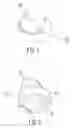
FIG. 1 is a perspective view of the skew light illumination lens device of the present invention.
FIG. 2 is a perspective view of the skew light illumination lens device of the present invention viewing from another angle.
FIG. 3 is a schematic view of the skew light illumination lens device of the present invention viewing from a front side.
FIG. 4 is a schematic view of the skew light illumination lens device of the present invention viewing from a lateral side.
FIG. 5 is a schematic view of the skew light illumination lens device of the present invention viewing from a top side.
FIG. 6 is a cross section view from a lateral side of the skew light illumination lens device of the present invention.
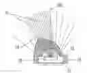
FIG. 7 is a cross section view and a schematic view showing the light refraction of the skew light illumination lens device of the present invention.
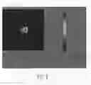
FIG. 8 is a simulated illumination distribution of the skew light illumination lens device of the present invention.
DETAILED DESCRIPTION OF THE INVENTION
In order that those skilled in the art can further understand the present invention, a description will be provided in the following in details. However, these descriptions and the appended drawings are only used to cause those skilled in the art to understand the objects, features, and characteristics of the present invention, but not to be used to confine the scope and spirit of the present invention defined in the appended claims.
Firstly, an preferable embodiment of a skew light illumination lens device according to the present invention is illustrated in FIGS. 1 to 7. The lens body includes a highly transparent base 10 with a receiving slot 11 which has a downwards opening serves to receive a illuminant device 20. A top side of the receving slot 11 is covered by a cancaved arc 12 for receviving the light emitting portion of the illuminant device as a light incident side. On the top of the base 10, a convex curved surface 13 is formed deviated from the light axis 100 with a predetermined angle as a light projecting side. The convex curved surface 13 has a highest point as a center, the thickness of the front and rear part of the convex curved surface 13 are gradually reduced asymmetric. The ratio of the width of the front to the rear part of the convex curved surface 13 is 4 to 1. The thickness of the left and right part of the convex curved surface 13 is gradually reduced symmetric.
Accordingly, the light 21 emitted from the illuminant device 20 will go through the cancaved arc 12 which is the incident side. The light 21 will be further refracted by the cancaved arc 12, the most part of the light will be gathered around the highest point of the convex curved surface 13 and a skew light illumination is so generated.
Furthermore, the angle between the line cross the highest point of the convex curved surface to the center of the concaved arc and the light axis 100 of the cancaved arc 12 and the base 10 is around 20 degrees to 40 degrees.
In FIG. 8, an illumination distribution showing a deviation diffusing of the light of the skew light illumination lens device according to the present invention is shown. By the design of the convex curved surface deviated from the light axis, the light will be gathered and projected with a predetermined angle from the light axis.
The present invention is thus described, it will be obvious that the same may be varied in many ways. Such variations are not to be regarded as a departure from the spirit and scope of the present invention, and all such modifications as would be obvious to one skilled in the art are intended to be included within the scope of the following claims.
Claims
What is claimed is:1. A skew light illumination lens device comprising a base with a receiving slot having a downwards opening for receiving a illuminant device; a top side of the receiving slot having a concaved arc; on a top side of the base, a convex curved surface being formed deviated from a light axis of the base; the light emitted from the illuminant device being refrated by the concaved arc and being gathered to a highest point of the convex curved surface so that a skew light illumination being generated.
2. The skew light illumination lens device as claimed in claim 1, wherein the thickness of the convex curved surface is decreased gradually outwards from the highest point thereof.
3. The skew light illumination lens device as claimed in claim 1, wherein the convex curved surface has a highest point as a center, the thickness of the front and the rear part of the convex curved surface are asymmetric, while the thickness of the left and the right part thereof are symmetric.
4. The skew light illumination lens device as claimed in claim 1, wherein the angle between the line cross the highest point of the convex curved surface to the center of the concaved arc and the light axis of the concaved arc and the base is around 20 degrees to 40 degrees.
5. The skew light illumination lens device as claimed in claim 1, wherein the base is a symmetric column body.
6. The skew light illumination lens device as claimed in claim 1, wherein the illuminant device is a Light Emitting Diode.
Images & Drawings included:


Sources:
- United States Patent and Trademark Office - verify current appl. status at the USPTO↗
Recent applications in this class:
- » 20250189099 2025-06-12
DISPLAY DEVICE, BACKLIGHT UNIT, LIGHT EMITTING MODULE AND LENS - » 20250155104 2025-05-15
Lens for Improved Color Mixing and Beam Control of an LED Light Source - » 20250116388 2025-04-10
LIGHTING ARRANGEMENT COMPRISING A LENS BODY - » 20250093014 2025-03-20
IPL LIGHT GUIDING DEVICE THAT REALIZES FRACTIONAL BY UTILIZING POLARIZATION FUNCTION - » 20250012424 2025-01-09
LINEAR LUMINAIRE ASSEMBLY WITH DETATCHABLE LENS ASSEMBLY - » 20240255118 2024-08-01
3D PRINTED INTERNAL CAVITY LENS FOR LIGHTING APPLICATIONS - » 20240247780 2024-07-25
APPARATUS AND METHOD FOR HIGH-EFFICIENTLY TUNING THE WAVELENGTH OF LIGHT USING COLLIMATING MODULE INCLUDING AN AXICON LENS - » 20240230061 2024-07-11
Lens for improved color mixing and beam control of an LED light source - » 20240167665 2024-05-23
STEERING DEVICE - » 20240167664 2024-05-23
OPTICAL ARRANGEMENT FOR COLLIMATED LIGHT BEAM