Electrode
US20100040901A1
2010-02-18
11/989,880
2006-07-28
✅ Patent granted
US 8,431,237 B2
2013-04-30
WO; PCT/IB2006/002065; 20060728
WO; WO2007/015131; 20070208
Michael La Villa
Nelson Mullins Riley & Scarborough LLP | Anthony A. Laurentano
2028-03-16
Abstract:
A method of forming an electrode includes casting a molten metal in a mould to form an electrode with a header portion and a blade portion. The blade portion of the electrode is then rolled after it has been cast. The blade portion may be rolled into at least two different thicknesses. In one embodiment the metal is lead or lead alloy and the method relates to the forming of a lead or lead alloy anode.
Assignee:
- John Thomas Turner 2 🇿🇦 Krugersdorp, South Africa
- Thomas John Meyer 2 🇿🇦 Krugersdorp, South Africa
Applicant:
Interested in similar patents?
Get notified when new applications in this technology area are published.
Classification:
B23P15/00 » CPC main
Making specific metal objects by operations not covered by a single other subclass or a group in this subclass
B22D19/00 » CPC further
Casting in, on, or around objects which form part of the product
B22D25/04 » CPC further
Special casting characterised by the nature of the product by its peculiarity of shape; of works of art Casting metal electric battery plates or the like
H01M4/685 » CPC further
Electrodes; Electrodes composed of, or comprising, active material; Carriers or collectors; Selection of materials for use in lead-acid accumulators Lead alloys
H01M4/84 » CPC further
Electrodes; Electrodes composed of, or comprising, active material; Carriers or collectors; Multi-step processes for manufacturing carriers for lead-acid accumulators involving casting
Y02E60/10 » CPC further
Enabling technologies; Technologies with a potential or indirect contribution to GHG emissions mitigation Energy storage using batteries
Y02E60/10 » CPC further
Enabling technologies; Technologies with a potential or indirect contribution to GHG emissions mitigation Energy storage using batteries
Y10T29/49991 » CPC further
Metal working; Method of mechanical manufacture; Combined manufacture including applying or shaping of fluent material; Metal casting Combined with rolling
Y10T428/12 » CPC further
Stock material or miscellaneous articles All metal or with adjacent metals
Y10T428/12389 » CPC further
Stock material or miscellaneous articles; All metal or with adjacent metals having variation in thickness
Y10T428/12403 » CPC further
Stock material or miscellaneous articles; All metal or with adjacent metals having variation in thickness Longitudinally smooth and symmetrical
Y10T428/12493 » CPC further
Stock material or miscellaneous articles; All metal or with adjacent metals Composite; i.e., plural, adjacent, spatially distinct metal components [e.g., layers, joint, etc.]
Y10T428/12694 » CPC further
Stock material or miscellaneous articles; All metal or with adjacent metals; Composite; i.e., plural, adjacent, spatially distinct metal components [e.g., layers, joint, etc.]; Pb- and Sn-base components: alternative to or next to each other and next to Cu- or Fe-base component
Y10T428/12701 » CPC further
Stock material or miscellaneous articles; All metal or with adjacent metals; Composite; i.e., plural, adjacent, spatially distinct metal components [e.g., layers, joint, etc.] Pb-base component
Y10T428/12903 » CPC further
Stock material or miscellaneous articles; All metal or with adjacent metals; Composite; i.e., plural, adjacent, spatially distinct metal components [e.g., layers, joint, etc.]; Transition metal-base component; Group VIII or IB metal-base component Cu-base component
Y10T428/2495 » CPC further
Stock material or miscellaneous articles; Structurally defined web or sheet [e.g., overall dimension, etc.] including components having same physical characteristic in differing degree Thickness [relative or absolute]
B32B3/00 IPC
Layered products comprising a layer with external or internal discontinuities or unevennesses, or a layer of non-planar form ; Layered products having particular features of form
B22D25/00 IPC
Special casting characterised by the nature of the product
B32B15/01 IPC
Layered products comprising a layer of metal all layers being exclusively metallic
B32B15/00 IPC
Layered products comprising a layer of metal
B32B15/04 IPC
Layered products comprising a layer of metal comprising metal as the main or only constituent of a layer, next to another layer of a
B32B15/20 IPC
Layered products comprising a layer of metal comprising aluminium or copper
Description
BACKGROUND OF THE INVENTION
This invention relates to an electrode and to a method for forming an electrode, typically a lead alloy anode.
Previously, electrodes were cast from a metal and had to be formed with a thicker blade for rigidity and corrosion resistance as cast metal, such as cast lead, typically corrodes faster than rolled metal.
Later developments have seen the manufacturing of the electrode by casting the header of the electrode and rolling the blade with the blade then being welded to the head.
However, this is relatively more difficult to manufacture.
The invention seeks to address this.
SUMMARY
According to one example embodiment a method of forming an electrode includes:
-
- casting a molten metal in a mould to form an electrode with a header portion and a blade portion; and
- rolling the blade portion of the electrode after it has been cast.
The method may include the rolling of the blade portion into at least two different thicknesses.
The method may also include inserting a second metal into the mould before the molten metal is cast into the mould.
The second metal may be copper.
In one aspect the metal is lead or lead alloy and the method relates to the forming of a lead or lead alloy anode.
The invention also extends to an electrode including:
-
- a cast header portion; and
- a rolled blade portion integrally formed with the header portion.
The blade portion has at least two different thicknesses.
The electrode may include a second metal moulded with the electrode.
The second metal may be copper.
In one example, the electrode is formed from lead or lead alloy and is a lead or lead alloy anode.
BRIEF DESCRIPTION OF THE DRAWINGS
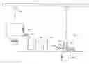
FIG. 1 shows an example plant for manufacturing electrodes according to one aspect;
FIG. 2 shows a schematic representation of an electrode formed using the plant of FIG. 1; and
FIG. 3 shows a schematic representation of an electrode after it has been cast but before it has been rolled.
DESCRIPTION OF PREFERRED EMBODIMENTS
An embodiment will be described with reference to the forming of lead alloy anodes but it will be appreciated that the methodology could be used with other metal or metal alloy electrodes such as the forming of aluminium cathodes to name but one example.
Referring to the accompanying Figures, a metal or metal alloy is passed into a melting pot 10.
The melting, pot is heated to a temperature range for example between 300° C. and 600° C., depending on the alloy, and the alloy is melted.
A second metal such as a copper bar, for example, is placed into a mould 12. Copper is used worldwide and is the preferred metal. The length shape and thickness of the copper hanger bar is determined by the weight and size of the anode to be formed.
Under the force of gravity melted lead alloy passes from the melting pot through connecting pipe 14 into the bottom of the mould 12, rising up and covering the copper bar.
Because the melted lead alloy is gravity fed from the bottom of the mould, this helps eliminate air pockets and impurities floating on the matter metal.
Once the metal has cooled sufficiently, it is placed in a cooling tank 16, if necessary.
Certain alloys do not require cooling in which case the cooling tank 16 will not be used.
The metal is moved from the mould 12 to the cooling tank 16 using an overhead crawl beam and hook contraption 18.
Thus the first step of casting the metal or the metal alloy in the mould is complete and the metal is now moved to a mould 20 in the form of a horizontal mould.
After the anode has been cast but before it is rolled its shape is as depicted in FIG. 3 with the thickness of the blade 32 being a thickness “A”.
The mould typically includes guide rollers 22 and compression rollers 24 which have a flywheel compression drive 26. As the cast metal passes through the horizontal rollers the cast metal is rolled and the shape of the cast metal changes.
If required, the electrode can be rolled and cross-rolled to spread in the molecules evenly.
After rolling the width of the blade 32 is as shown in FIG. 2 with thickness “B” and “C” being less than the thickness “A” in FIG. 3.
The thickness of the casting before rolling will be ascertained by the required finished thickness and will typically need to be compressed by between about 30% and 70% depending on the alloy in use. In the illustrated embodiment this amounted to about 3 mm.
In any event, the compression rollers 24 typically start in a more open position to allow the part of the electrode with the copper insert to pass through towards the pit 28.
Once the copper portion has passed through to a predetermined position, the compression rollers begin closing to compress the portion of the metal or metal alloy behind the copper portion.
In this manner, the copper header bar 30 and blade 32 are integrally formed without requiring the welding of the header to the blade.
The header is typically not rolled at all since it is not immersed in the solution and is not subject to corrosion.
The electrode is then trimmed and fettled ready for dispatch.
It will be appreciated that where the electrode corrodes quicker at solution level, the electrode can be rolled thicker from the header to approximately 30 mm below the solution level while the remainder of the blade can be rolled as required. An example of this can be seen in FIG. 2.
Thus the electrode will have three different thicknesses. One example of these different thicknesses is illustrated in the accompanying drawing.
In any event, the method is suitable for any metal or metal alloy electrode and will give required electrical conductivity and mechanical strength of rolled metal or metal alloy but with a simpler and less costly manufacturing process than previous designs.
In addition, the methodology allows existing lead anodes to be recast and rolled to provide the improved structure.
Claims
1. A method of forming an electrode, the method including:
casting a molten metal in a mold to form an electrode with a header portion and a blade portion; and
rolling the blade portion of the electrode after it has been cast.
2. A method according to claim 1 further comprising rolling the blade portion into at least two different thicknesses.
3. A method according to claim 1 further comprising inserting a second metal into the mold before the molten metal is cast into the mold.
4. A method according to claim 3 wherein the second metal is copper.
5. A method according to claim 1 wherein the metal is lead or lead alloy.
6. A method according to claim 5 further comprising forming an anode.
7. An electrode, comprising:
a cast header portion; and
a rolled blade portion integrally formed with the header portion.
8. An electrode according to claim 7 wherein the blade portion has at least two different thicknesses.
9. An electrode according to claim 7 wherein the electrode is formed from first and second metals.
10. An electrode according to claim 9 wherein the second metal is copper.
11. An electrode according to claim 7 wherein the electrode is formed from lead or lead alloy.
12. An electrode according to claim 11 wherein the electrode is a lead or lead alloy anode.
13. An electrode according to claim 7, wherein the first metal is lead or lead alloy.
Images & Drawings included:

Sources:
- United States Patent and Trademark Office - verify current appl. status at the USPTO↗
Similar patent applications:
- » 20250132344
SURFACE TREATMENT AGENT FOR ELECTRODE MATERIAL, POSITIVE ELECTRODE ACTIVE MATERIAL, CURRENT COLLECTOR FOIL, NEGATIVE ELECTRODE ACTIVE MATERIAL, CONDUCTIVE AID, ELECTRODE, BATTERY, METHOD FOR MANUFACTURING POSITIVE ELECTRODE ACTIVE MATERIAL, METHOD FOR MANUFACTURING CURRENT COLLECTOR FOIL, METHOD FOR MANUFACTURING NEGATIVE ELECTRODE ACTIVE MATERIAL, METHOD FOR MANUFACTURING CONDUCTIVE AID, AND METHOD FOR MANUFACTURING ELECTRODE - » 20060092367
Thin film transistor array panel having a pixel electrode including a first subpixel electrode and a second subpixel electrode connected to the drain electrode of the thin film transistor and a third subpixel electrode capacitively coupled to a coupling electrode extended from the drain electrode - » 20240079582
POSITIVE ELECTRODE ACTIVE MATERIAL FOR LITHIUM ION BATTERIES, POSITIVE ELECTRODE FOR LITHIUM ION BATTERIES, LITHIUM ION BATTERY, POSITIVE ELECTRODE ACTIVE MATERIAL FOR ALL-SOLID LITHIUM ION BATTERIES, POSITIVE ELECTRODE FOR ALL-SOLID LITHIUM ION BATTERIES, ALL-SOLID LITHIUM ION BATTERY, METHOD FOR PRODUCING POSITIVE ELECTRODE ACTIVE MATERIAL FOR LITHIUM ION BATTERIES, AND METHOD FOR PRODUCING POSITIVE ELECTRODE ACTIVE MATERIAL FOR ALL-SOLID LITHIUM ION BATTERIES - » 20210234067
Electrode assembly having lower electrode directly on the surface of a base substrate, a first electrode on the lower electrode, and the second electrode formed on and spaced apart from the first electrode - » 20140308592
METHOD OF MANUFACTURING DISPERSION LIQUID FOR ELECTRODE CATALYST, DISPERSION LIQUID FOR ELECTRODE CATALYST, METHOD OF MANUFACTURING ELECTRODE CATALYST, ELECTRODE CATALYST, ELECTRODE STRUCTURE, MEMBRANE ELECTRODE ASSEMBLY, FUEL CELL AND AIR CELL - » 20240222632
NEGATIVE ELECTRODE PRE-DISPERSION SOLUTION, NEGATIVE ELECTRODE COMPOSITION INCLUDING SAME, NEGATIVE ELECTRODE FOR LITHIUM SECONDARY BATTERY INCLUDING NEGATIVE ELECTRODE COMPOSITION, LITHIUM SECONDARY BATTERY INCLUDING NEGATIVE ELECTRODE, AND METHOD FOR PRODUCING NEGATIVE ELECTRODE COMPOSITION - » 20210210740
Dispersant for electrode coating liquid, electrode coating liquid composition including the dispersant for electrode coating liquid, electrode for power storage device manufactured using the electrode coating liquid composition, and power storage device having the electrode - » 20150280266
BIOFUEL CELL, METHOD FOR PRODUCTION OF BIOFUEL CELL, ELECTRONIC DEVICE, ENZYME IMMOBILIZATION ELECTRODE, METHOD FOR PRODUCTION OF ENZYME IMMOBILIZATION ELECTRODE, ELECTRODE FOR PRODUCTION OF ENZYME IMMOBILIZATION ELECTRODE, METHOD FOR 5 PRODUCTION OF ELECTRODE FOR PRODUCTION OF ENZYME IMMOBILIZATION ELECTRODE AND ENZYME REACTION USING DEVICE - » 20220149079
Pixel in a display area having a plurality of repair patterns/circuit overlapping between a pair of plurality of electrodes including a first electrode and a second electrode that are spaced apart from each other and an intermediate electrode arranged between the first electrode and the second electrode, and display device comprising the pixel - » 20090325069
Binder for electrode formation, slurry for electrode formation using the binder, electrode using the slurry, rechargeable battery using the electrode, and capacitor using the electrode
Recent applications in this class:
- » 20250196274 2025-06-19
METHOD OF MANUFACTURING A TURBINE SHROUD SEGMENT - » 20250153286 2025-05-15
METHOD OF MANUFACTURING INTEGRALLY FORGED BIKE SUSPENSION FORK - » 20240308005 2024-09-19
METHOD OF MANUFACTURING TUBULAR HOLLOW PROFILE VEHICLE FRAME PARTS - » 20230405743 2023-12-21
Piping spool auto manufacturing system - » 20230049566 2023-02-16
Methods for forming cooling apertures in a turbine engine component - » 20220410326 2022-12-29
MACHINING METHOD FOR ULTRA-HIGH STRENGTH STEEL HIGH-ASPECT-RATIO WIND TUNNEL TEST MODEL PART - » 20220288728 2022-09-15
Method of surface texturing for a writing instrument tip - » 20220234150 2022-07-28
Method of Using Improved Crossbar Connection for Implements - » 20220184754 2022-06-16
Holding table manufacturing method - » 20220152752 2022-05-19
Manufacturing method of staple-less binding unit
Recent applications for this Assignee:
- » 20130212866 2013-08-22
Method for forming an electrode - » 20130212866 2013-08-22
Method for forming an electrode