Structure to protect occupants from storm debris
US20100058693A1
2010-03-11
12/283,258
2008-09-11
Abstract:
A structure to protect occupants from storm debris comprising components that are pre-fabricated and assembled on site. Upon assembly, the void cavities in the floor, walls and ceilings are pumped with concrete to increase the unit strength and stability.
Interested in similar patents?
Get notified when new applications in this technology area are published.
Classification:
E04B1/161 » CPC main
Constructions in general; Structures which are not restricted either to walls, e.g. partitions, or floors or ceilings or roofs; Structures made from masses, e.g. of concrete, cast or similarly formed with or without making use of additional elements, such as permanent forms, substructures to be coated with load-bearing material with vertical and horizontal slabs, both being partially cast
E04H9/14 » CPC further
Buildings, or groups of buildings, or shelters adapted to withstand or provide protection against abnormal external influences, e.g. war-like action, earthquake, extreme climate against other dangerous influences, e.g. tornadoes, floods
E04B2/8647 » CPC further
Walls, e.g. partitions, for buildings; Wall construction with regard to insulation; Connections specially adapted to walls; Walls made by casting, pouring, or tamping made in permanent forms with ties going through the forms
Y02A50/00 » CPC further
in human health protection, e.g. against extreme weather
E04B1/00 IPC
Constructions in general; Structures which are not restricted either to walls, e.g. partitions, or floors or ceilings or roofs
Description
BACKGROUND
This invention relates to in-residence storm shelters. The need is addressed by the Federal Emergency Management Agency (FEMA) as well as various universities and groups. The common recommended method of using conventional building materials to achieve the desired protection level is by far exceeded with the present invention. The present invention will be packaged as a kit in which the components can be easily handled by 2 people and assembled prior to pumping concrete into the formed voids, (floor, wall and ceiling cavities) rather than the use of common building materials.
SUMMARY OF INVENTION
It is an object of the present invention to provide a structure to protect the occupants of the structure from debris generated by storms (I.E. tornadoes, hurricanes, etc.) The intent is to provide a structure that can be assembled in a desired location according to a prescribed method, and then reinforced with concrete fill which upon curing will substantially add to the strength of the structure and also increase the structure's weight, vastly increasing its stability. The structure size can be increased by increasing the quantity of identical floor plates, top plates, wall plates, ceiling plates, etc. . . . described in the drawings. The fasteners discussed here-in are the preferred choice although alternate bolt and nut combinations and/or drilling and tapping of holes will accomplish the same result.
BRIEF DESCRIPTION OF DRAWINGS
FIG. 1 Orthographic door end view of structure
FIG. 2 Orthographic side view of structure
FIG. 3 Orthographic rear view of structure
FIG. 4 Orthographic top view of structure
FIG. 5 Section view taken at plane 5-5 (see FIG. 4)
FIG. 6 Section view taken at plane 6-6 (see FIG. 5)
FIG. 7 Isometric view—partially assembled
FIG. 8 Isometric view—partially assembled
FIG. 9 Isometric view—partially assembled
FIG. 10 Isometric view—partially assembled
FIG. 11 Isometric view—partially assembled
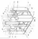
FIG. 12 Isometric view—completely assembled
DETAILED DESCRIPTION OF DRAWINGS
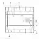
FIG. 1 Orthographic Door End View of Structure:
Door (19) is hinge mounted from corner structure (5). Door (19) is provided with ventilation slots and baffle plates (21 & 22) to prevent direct entry of debris into occupant chamber.
FIG. 2 Orthographic Side View of Structure:
Corner structure (5) is mounted on base plate weldments (1 & 3) utilizing self threading cap screws (25). Spacer pads (4) are provided to elevate outside corner of plates to prevent interference with radius formed in bent plates. Braces (6 & 7) are provided to align and hold parts in desired location and secured with self threading cap screws (25). Top plates (17 & 18) are mounted on structure utilizing self threading cap screws (25). Top plate (17) and top plate (18) are joined to one another utilizing self threading cap screws (25) on lower surface before ceiling panels (23) are installed.
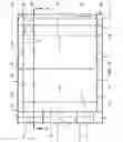
FIG. 3 Orthographic Rear View of Structure:
Corners (5) are held in proper alignment utilizing braces (6 & 7) and secured to base plates (1 & 3) utilizing self threading cap screws (25). End plate (14) is fastened to corners (5), base plate (3) and top plate (17) utilizing self threading cap screws (25). End plate (14) is provided with ventilation slots and baffle plates (21 & 22) to prevent direct entry of debris into occupant chamber.
FIG. 4 Orthographic Top View of Structure:
Top plates (17 & 18) fasten to each other utilizing self threading cap screws (25) and fasten to structure utilizing self threading cap screws (25). Spacer pads (4) are utilized to prevent interference of corners of plates with radius formed in bent plates.
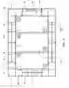
FIG. 5 Section View Taken at Cutting Plane 5-5 (See FIG. 4):
Ceiling plates (23) are fastened to corners (5), wall interior panels (11) and top plates (17 & 18) utilizing self threading cap screws (25). Clearance holes are provided in outside wall plates (12 & 14) and inside plates (11 & 15) to accept tension bolt/nut assembly (13) to minimize plate swellage during concrete filling.
FIG. 6 Section View Taken at Cutting Plane 6-6 (See FIG. 5):
Floor plates (6) are secured on base plates (1, 2 & 3), interior wall plates (11 & 15) and corner weldments (5) utilizing self threading cap screws (25). % turn plugs (20) are provided for filling empty cavities with concrete upon completion of assembly per FIG. 12.
FIG. 7 Isometric View—Partially Assembled (Step 1):
Floor plate sub-weldments (1, 2 & 3) join to one another utilizing self threading cap screws (25). Spacer pads (4) are provided to elevate corners of mating plates to prevent interference with radius formed in bent plates.
FIG. 8 Isometric View—Partially Assembled (Step 2):
Added components—corner sub-weldments (5), columns (8), braces (6 & 7), doorway ceiling plate (10), and doorway end plates (24) are fastened utilizing self threading cap screws (25).
FIG. 9 Isometric View—Partially Assembled (Step 3):
Added components—interior wall plates (11, 12 & 15), exterior wall plates (12 & 14) and floor plates (9 & 10) are fastened utilizing self threading cap screws (25). Door stop bars (16) are attached to corners (5) preferably by welding, Clearance holes are provided in outside wall plates (12 & 14) and inside plates (11 & 15) to accept tension bolt/nut assembly (13) to minimize plate swellage during concrete filling.
FIG. 10 Isometric View—Partially Assembled (Step 4):
Door (19) is hinge mounted on corner (5). Top plate sub-weldments (17 & 18) are fastened to each other and into structure utilizing self threading cap screws (25).
FIG. 11 Isometric View—Partially Assembled (Illustration Only):
Top plates (17 & 18) are omitted in this view for clarity. Ceiling plates (23) are fastened into structure utilizing self threading cap screws (25)
FIG. 12 Isometric View—Completely Assembled:
Structure at this stage is ready for concrete filling (preferably utilizing a concrete pumping machine and a concrete vibrator). Cavities to be filled would be filled in sequence as marked (E.I.—Both plugs marked “A” would be removed until concrete appears fully at both openings, then stop filling and replace plugs. Proceed to both plugs marked “B” and repeat sequence for all plugs until all cavities are filled.
Claims
What is claimed:1. A structure for protection of occupants comprising:
Prefabricated components to be assembled using common hand tools and a minimum number of personnel.
2. A structure as defined in claim 1 further comprising:
Cavities in floor, walls, corners, and ceiling to be filled with concrete.
3. A structure as defined in claim 2 further comprising:
Baffled ventilation method in the door and walls utilizing ventilation slots in door and back plate as well as baffle plates behind slots.
4. A structure as defined in claim 2 further comprising:
Provision for assembly and alignment of components utilizing prefabricated braces and attachments
5. A structure as defined in claim 2 further comprising:
Provision to prevent swelling of panels when filling with concrete utilizing tension bolts and nuts.
6. A structure as defined in claim 2 further comprising:
Provision to assure total filling of all individual cavities when installing concrete fill utilizing ¼ turn plugs for filling and inspection.
7. A structure as defined in claim 2 further comprising:
Ability to expand in size by increasing quantity of identical components.
(Varying the quantity of floor plates, inside wall plates, outside wall plates and top plates, etc.)
Images & Drawings included:


Sources:
- United States Patent and Trademark Office - verify current appl. status at the USPTO↗
Similar patent applications:
- » 20110138701
Structure to protect occupants from storm debris
Recent applications in this class:
- » 20230340772 2023-10-26
Automated Self-Installing Concrete Formwork - » 20220154444 2022-05-19
Method of constructing a modular building, a tray-like modular building component, and related method, and a modular building column assembly - » 20220018112 2022-01-20
Modular building systems - » 20210071409 2021-03-11
HIGH-RISE SELF-SUPPORTING FORMWORK BUILDING SYSTEM - » 20190211542 2019-07-11
Method of constructing a modular building, a tray-like modular building component, and related method, and a modular building column assembly - » 20180051456 2018-02-22
Disaster-resistant structure and method for securing disaster-resistant structures to a body of cast material - » 20150113885 2015-04-30
METHOD OF ERECTING POLYGONAL REINFORCED ENCLOSURE IN SITU - » 20140259979 2014-09-18
Component building system - » 20130047539 2013-02-28
Building Structure - » 20130019549 2013-01-24
Prefabricated insulation wall panels for construction of walls