Printhead nozzle arrangement having ink ejecting actuators annularly arranged around ink ejection port
US20100149255A1
2010-06-17
12/710,278
2010-02-22
✅ Patent granted
US 7,971,969 B2
2011-07-05
-
-
An H Do
2030-02-22
Abstract:
A printhead for an inkjet printer includes a wafer defining a plurality of nozzle chambers and a plurality of ink supply channel in fluid communication with the plurality of nozzle chambers for supplying the plurality of nozzle chambers with ink; an ink ejection port associated with each nozzle chamber; and a plurality of actuators associated with each nozzle chamber, the plurality of actuators each including a petal formation. A plurality of petal formations are arranged around an ink ejection port of each nozzle chamber to annularly surround the ink ejection port. Each actuator is operable to displace a respective petal formation into the nozzle chamber.
Inventors:
- Kia Silverbrook 4,816 🇦🇺 Balmain, Australia
- Gregory John McAvoy 178 🇦🇺 Balmain, Australia
Assignee:
- Silverbrook Research Pty Ltd 3,043 🇦🇺 Balmain, New South Wales, Australia
Interested in similar patents?
Get notified when new applications in this technology area are published.
Classification:
B41J2/14427 » CPC main
Typewriters or selective printing mechanisms characterised by the printing or marking process for which they are designed characterised by bringing liquid or particles selectively into contact with a printing material; Ink jet; Nozzles; Structure thereof only for on-demand ink jet heads Structure of ink jet print heads with thermal bend detached actuators
B41J2/1433 » CPC further
Typewriters or selective printing mechanisms characterised by the printing or marking process for which they are designed characterised by bringing liquid or particles selectively into contact with a printing material; Ink jet; Nozzles; Structure thereof only for on-demand ink jet heads Structure of nozzle plates
B41J2/1623 » CPC further
Typewriters or selective printing mechanisms characterised by the printing or marking process for which they are designed characterised by bringing liquid or particles selectively into contact with a printing material; Ink jet; Nozzles; Production of nozzles manufacturing processes bonding and adhesion
B41J2/1631 » CPC further
Typewriters or selective printing mechanisms characterised by the printing or marking process for which they are designed characterised by bringing liquid or particles selectively into contact with a printing material; Ink jet; Nozzles; Production of nozzles manufacturing processes photolithography
B41J2/1632 » CPC further
Typewriters or selective printing mechanisms characterised by the printing or marking process for which they are designed characterised by bringing liquid or particles selectively into contact with a printing material; Ink jet; Nozzles; Production of nozzles manufacturing processes machining
B41J2/1635 » CPC further
Typewriters or selective printing mechanisms characterised by the printing or marking process for which they are designed characterised by bringing liquid or particles selectively into contact with a printing material; Ink jet; Nozzles; Production of nozzles manufacturing processes dividing the wafer into individual chips
B41J2/1637 » CPC further
Typewriters or selective printing mechanisms characterised by the printing or marking process for which they are designed characterised by bringing liquid or particles selectively into contact with a printing material; Ink jet; Nozzles; Production of nozzles manufacturing processes molding
B41J2/1648 » CPC further
Typewriters or selective printing mechanisms characterised by the printing or marking process for which they are designed characterised by bringing liquid or particles selectively into contact with a printing material; Ink jet; Nozzles; Production of nozzles Production of print heads with thermal bend detached actuators
B41J2/17596 » CPC further
Typewriters or selective printing mechanisms characterised by the printing or marking process for which they are designed characterised by bringing liquid or particles selectively into contact with a printing material; Ink jet characterised by ink handling; Ink supply systems ; Circuit parts therefor Ink pumps, ink valves
B41J2002/041 » CPC further
Typewriters or selective printing mechanisms characterised by the printing or marking process for which they are designed characterised by bringing liquid or particles selectively into contact with a printing material; Ink jet characterised by the jet generation process generating single droplets or particles on demand Electromagnetic transducer
B41J2002/14346 » CPC further
Typewriters or selective printing mechanisms characterised by the printing or marking process for which they are designed characterised by bringing liquid or particles selectively into contact with a printing material; Ink jet; Nozzles; Structure thereof only for on-demand ink jet heads Ejection by pressure produced by thermal deformation of ink chamber, e.g. buckling
B41J2002/14435 » CPC further
Typewriters or selective printing mechanisms characterised by the printing or marking process for which they are designed characterised by bringing liquid or particles selectively into contact with a printing material; Ink jet; Nozzles; Structure thereof only for on-demand ink jet heads; Structure of ink jet print heads with thermal bend detached actuators Moving nozzle made of thermal bend detached actuator
B41J2002/14475 » CPC further
Typewriters or selective printing mechanisms characterised by the printing or marking process for which they are designed characterised by bringing liquid or particles selectively into contact with a printing material; Ink jet; Nozzles; Structure thereof only for on-demand ink jet heads characterised by nozzle shapes or number of orifices per chamber
B41J2202/15 » CPC further
Embodiments of or processes related to ink-jet or thermal heads; Embodiments of or processes related to ink-jet heads Moving nozzle or nozzle plate
Y10T29/49401 » CPC further
Metal working; Method of mechanical manufacture Fluid pattern dispersing device making, e.g., ink jet
B41J2/145 IPC
Typewriters or selective printing mechanisms characterised by the printing or marking process for which they are designed characterised by bringing liquid or particles selectively into contact with a printing material; Ink jet; Nozzles Arrangement thereof
B41J2/05 IPC
Typewriters or selective printing mechanisms characterised by the printing or marking process for which they are designed characterised by bringing liquid or particles selectively into contact with a printing material; Ink jet characterised by the jet generation process generating single droplets or particles on demand by pressure, e.g. electromechanical transducers produced by the application of heat
B41J2/04 IPC
Typewriters or selective printing mechanisms characterised by the printing or marking process for which they are designed characterised by bringing liquid or particles selectively into contact with a printing material; Ink jet characterised by the jet generation process generating single droplets or particles on demand
Description
CROSS REFERENCES TO RELATED APPLICATIONS
The present application is a Continuation Application of U.S. patent application Ser. No. 12/277,295 filed on Nov. 24, 2008, which is a Continuation Application of U.S. patent application Ser. No. 12/025,605 filed on Feb. 4, 2008, now issued U.S. Pat. No. 7,465,029, which is a Continuation of U.S. application Ser. No. 11/655,987 filed Jan. 22, 2007, now issued U.S. Pat. No. 7,347,536, which is a Continuation of U.S. application Ser. No. 11/084,752 filed Mar. 21, 2005, now issued U.S. Pat. No. 7,192,120, which is a Continuation of U.S. application Ser. No. 10/636,255 filed Aug. 8, 2003, now issued U.S. Pat. No. 6,959,981, which is a continuation of Ser. No. 09/854,703 filed May 14, 2001, now issued U.S. Pat. No. 6,981,757, which is a Continuation of U.S. application Ser. No. 09/112,806 filed Jul. 10, 1998, now issued as U.S. Pat. No. 6,247,790, all of which are herein incorporated by reference.
The following Australian provisional patent applications are hereby incorporated by cross-reference. For the purposes of location and identification, US patent applications identified by their US patent application serial numbers (USSN) are listed alongside the Australian applications from which the US patent applications claim the right of priority.
| CROSS- | US PATENT/PATENT | |
| REFERENCED | APPLICATION | |
| AUSTRALIAN | (CLAIMING RIGHT | |
| PROVISIONAL | OF PRIORITY FROM | |
| PATENT | AUSTRALIAN PROVISIONAL | |
| APPLICATION No. | APPLICATION) | DOCKET No. |
| PO7991 | 6,750,901 | ART01US |
| PO8505 | 6,476,863 | ART02US |
| PO7988 | 6,788,336 | ART03US |
| PO9395 | 6,322,181 | ART04US |
| PO8017 | 6,597,817 | ART06US |
| PO8014 | 6,227,648 | ART07US |
| PO8025 | 6,727,948 | ART08US |
| PO8032 | 6,690,419 | ART09US |
| PO7999 | 6,727,951 | ART10US |
| PO8030 | 6,196,541 | ART13US |
| PO7997 | 6,195,150 | ART15US |
| PO7979 | 6,362,868 | ART16US |
| PO7978 | 6,831,681 | ART18US |
| PO7982 | 6,431,669 | ART19US |
| PO7989 | 6,362,869 | ART20US |
| PO8019 | 6,472,052 | ART21US |
| PO7980 | 6,356,715 | ART22US |
| PO8018 | 6,894,694 | ART24US |
| PO7938 | 6,636,216 | ART25US |
| PO8016 | 6,366,693 | ART26US |
| PO8024 | 6,329,990 | ART27US |
| PO7939 | 6,459,495 | ART29US |
| PO8501 | 6,137,500 | ART30US |
| PO8500 | 6,690,416 | ART31US |
| PO7987 | 7,050,143 | ART32US |
| PO8022 | 6,398,328 | ART33US |
| PO8497 | 7,110,024 | ART34US |
| PO8020 | 6,431,704 | ART38US |
| PO8504 | 6,879,341 | ART42US |
| PO8000 | 6,415,054 | ART43US |
| PO7934 | 6,665,454 | ART45US |
| PO7990 | 6,542,645 | ART46US |
| PO8499 | 6,486,886 | ART47US |
| PO8502 | 6,381,361 | ART48US |
| PO7981 | 6,317,192 | ART50US |
| PO7986 | 6,850,274 | ART51US |
| PO7983 | 09/113,054 | ART52US |
| PO8026 | 6,646,757 | ART53US |
| PO8028 | 6,624,848 | ART56US |
| PO9394 | 6,357,135 | ART57US |
| PO9397 | 6,271,931 | ART59US |
| PO9398 | 6,353,772 | ART60US |
| PO9399 | 6,106,147 | ART61US |
| PO9400 | 6,665,008 | ART62US |
| PO9401 | 6,304,291 | ART63US |
| PO9403 | 6,305,770 | ART65US |
| PO9405 | 6,289,262 | ART66US |
| PP0959 | 6,315,200 | ART68US |
| PP1397 | 6,217,165 | ART69US |
| PP2370 | 6,786,420 | DOT01US |
| PO8003 | 6,350,023 | Fluid01US |
| PO8005 | 6,318,849 | Fluid02US |
| PO8066 | 6,227,652 | IJ01US |
| PO8072 | 6,213,588 | IJ02US |
| PO8040 | 6,213,589 | IJ03US |
| PO8071 | 6,231,163 | IJ04US |
| PO8047 | 6,247,795 | IJ05US |
| PO8035 | 6,394,581 | IJ06US |
| PO8044 | 6,244,691 | IJ07US |
| PO8063 | 6,257,704 | IJ08US |
| PO8057 | 6,416,168 | IJ09US |
| PO8056 | 6,220,694 | IJ10US |
| PO8069 | 6,257,705 | IJ11US |
| PO8049 | 6,247,794 | IJ12US |
| PO8036 | 6,234,610 | IJ13US |
| PO8048 | 6,247,793 | IJ14US |
| PO8070 | 6,264,306 | IJ15US |
| PO8067 | 6,241,342 | IJ16US |
| PO8001 | 6,247,792 | IJ17US |
| PO8038 | 6,264,307 | IJ18US |
| PO8033 | 6,254,220 | IJ19US |
| PO8002 | 6,234,611 | IJ20US |
| PO8068 | 6,302,528 | IJ21US |
| PO8062 | 6,283,582 | IJ22US |
| PO8034 | 6,239,821 | IJ23US |
| PO8039 | 6,338,547 | IJ24US |
| PO8041 | 6,247,796 | IJ25US |
| PO8004 | 6,557,977 | IJ26US |
| PO8037 | 6,390,603 | IJ27US |
| PO8043 | 6,362,843 | IJ28US |
| PO8042 | 6,293,653 | IJ29US |
| PO8064 | 6,312,107 | IJ30US |
| PO9389 | 6,227,653 | IJ31US |
| PO9391 | 6,234,609 | IJ32US |
| PP0888 | 6,238,040 | IJ33US |
| PP0891 | 6,188,415 | IJ34US |
| PP0890 | 6,227,654 | IJ35US |
| PP0873 | 6,209,989 | IJ36US |
| PP0993 | 6,247,791 | IJ37US |
| PP0890 | 6,336,710 | IJ38US |
| PP1398 | 6,217,153 | IJ39US |
| PP2592 | 6,416,167 | IJ40US |
| PP2593 | 6,243,113 | IJ41US |
| PP3991 | 6,283,581 | IJ42US |
| PP3987 | 6,247,790 | IJ43US |
| PP3985 | 6,260,953 | IJ44US |
| PP3983 | 6,267,469 | IJ45US |
| PO7935 | 6,224,780 | IJM01US |
| PO7936 | 6,235,212 | IJM02US |
| PO7937 | 6,280,643 | IJM03US |
| PO8061 | 6,284,147 | IJM04US |
| PO8054 | 6,214,244 | IJM05US |
| PO8065 | 6,071,750 | IJM06US |
| PO8055 | 6,267,905 | IJM07US |
| PO8053 | 6,251,298 | IJM08US |
| PO8078 | 6,258,285 | IJM09US |
| PO7933 | 6,225,138 | IJM10US |
| PO7950 | 6,241,904 | IJM11US |
| PO7949 | 6,299,786 | IJM12US |
| PO8060 | 6,866,789 | IJM13US |
| PO8059 | 6,231,773 | IJM14US |
| PO8073 | 6,190,931 | IJM15US |
| PO8076 | 6,248,249 | IJM16US |
| PO8075 | 6,290,862 | IJM17US |
| PO8079 | 6,241,906 | IJM18US |
| PO8050 | 6,565,762 | IJM19US |
| PO8052 | 6,241,905 | IJM20US |
| PO7948 | 6,451,216 | IJM21US |
| PO7951 | 6,231,772 | IJM22US |
| PO8074 | 6,274,056 | IJM23US |
| PO7941 | 6,290,861 | IJM24US |
| PO8077 | 6,248,248 | IJM25US |
| PO8058 | 6,306,671 | IJM26US |
| PO8051 | 6,331,258 | IJM27US |
| PO8045 | 6,110,754 | IJM28US |
| PO7952 | 6,294,101 | IJM29US |
| PO8046 | 6,416,679 | IJM30US |
| PO9390 | 6,264,849 | IJM31US |
| PO9392 | 6,254,793 | IJM32US |
| PP0889 | 6,235,211 | IJM35US |
| PP0887 | 6,491,833 | IJM36US |
| PP0882 | 6,264,850 | IJM37US |
| PP0874 | 6,258,284 | IJM38US |
| PP1396 | 6,312,615 | IJM39US |
| PP3989 | 6,228,668 | IJM40US |
| PP2591 | 6,180,427 | IJM41US |
| PP3990 | 6,171,875 | IJM42US |
| PP3986 | 6,267,904 | IJM43US |
| PP3984 | 6,245,247 | IJM44US |
| PP3982 | 6,315,914 | IJM45US |
| PP0895 | 6,231,148 | IR01US |
| PP0869 | 6,293,658 | IR04US |
| PP0887 | 6,614,560 | IR05US |
| PP0885 | 6,238,033 | IR06US |
| PP0884 | 6,312,070 | IR10US |
| PP0886 | 6,238,111 | IR12US |
| PP0877 | 6,378,970 | IR16US |
| PP0878 | 6,196,739 | IR17US |
| PP0883 | 6,270,182 | IR19US |
| PP0880 | 6,152,619 | IR20US |
| PO8006 | 6,087,638 | MEMS02US |
| PO8007 | 6,340,222 | MEMS03US |
| PO8010 | 6,041,600 | MEMS05US |
| PO8011 | 6,299,300 | MEMS06US |
| PO7947 | 6,067,797 | MEMS07US |
| PO7944 | 6,286,935 | MEMS09US |
| PO7946 | 6,044,646 | MEMS10US |
| PP0894 | 6,382,769 | MEMS13US |
FIELD OF THE INVENTION
The present invention relates to the field of inkjet printing and, in particular, discloses an inverted radial back-curling thermoelastic ink jet printing mechanism.
BACKGROUND OF THE INVENTION
Many different types of printing mechanisms have been invented, a large number of which are presently in use. The known forms of printers have a variety of methods for marking the print media with a relevant marking media. Commonly used forms of printing include offset printing, laser printing and copying devices, dot matrix type impact printers, thermal paper printers, film recorders, thermal wax printers, dye sublimation printers and ink jet printers both of the drop on demand and continuous flow type. Each type of printer has its own advantages and problems when considering cost, speed, quality, reliability, simplicity of construction and operation etc.
In recent years the field of ink jet printing, wherein each individual pixel of ink is derived from one or more ink nozzles, has become increasingly popular primarily due to its inexpensive and versatile nature.
Many different techniques of ink jet printing have been invented. For a survey of the field, reference is made to an article by J Moore, “Non-Impact Printing: Introduction and Historical Perspective”, Output Hard Copy Devices, Editors R Dubeck and S Sherr, pages 207-220 (1988).
Ink Jet printers themselves come in many different forms. The utilization of a continuous stream of ink in ink jet printing appears to date back to at least 1929 wherein U.S. Pat. No. 1,941,001 by Hansell discloses a simple form of continuous stream electro-static ink jet printing.
U.S. Pat. No. 3,596,275 by Sweet also discloses a process of a continuous ink jet printing including a step wherein the ink jet stream is modulated by a high frequency electro-static field so as to cause drop separation. This technique is still utilized by several manufacturers including Elmjet and Scitex (see also U.S. Pat. No. 3,373,437 by Sweet et al).
Piezoelectric ink jet printers are also one form of commonly utilized ink jet printing device. Piezoelectric systems are disclosed by Kyser et. al. in U.S. Pat. No. 3,946,398 (1970) which utilizes a diaphragm mode of operation, by Zolten in U.S. Pat. No. 3,683,212 (1970) which discloses a squeeze mode form of operation of a piezoelectric crystal, Stemme in US Patent No. 3,747,120 (1972) which discloses a bend mode of piezoelectric operation, Howkins in US Patent No. 4,459,601 which discloses a piezoelectric push mode actuation of the ink jet stream and Fischbeck in U.S. Pat. No. 4,584,590 which discloses a shear mode type of piezoelectric transducer element.
Recently, thermal ink jet printing has become an extremely popular form of ink jet printing. The ink jet printing techniques include those disclosed by Endo et al in GB 2007162 (1979) and Vaught et al in U.S. Pat. No. 4,490,728. Both the aforementioned references disclose ink jet printing techniques which rely on the activation of an electrothermal actuator which results in the creation of a bubble in a constricted space, such as a nozzle, which thereby causes the ejection of ink from an aperture connected to the confined space onto a relevant print media. Printing devices utilizing the electro-thermal actuator are manufactured by manufacturers such as Canon and Hewlett Packard.
As can be seen from the foregoing, many different types of printing technologies are available. Ideally, a printing technology should have a number of desirable attributes. These include inexpensive construction and operation, high speed operation, safe and continuous long term operation etc. Each technology may have its own advantages and disadvantages in the areas of cost, speed, quality, reliability, power usage, simplicity of construction and operation, durability and consumables.
SUMMARY OF THE INVENTION
According to an aspect of the present disclosure, aA printhead for an inkjet printer includes a wafer defining a plurality of nozzle chambers and a plurality of ink supply channel in fluid communication with the plurality of nozzle chambers for supplying the plurality of nozzle chambers with ink; an ink ejection port associated with each nozzle chamber; and a plurality of actuators associated with each nozzle chamber, the plurality of actuators each including a petal formation. A plurality of petal formations are arranged around an ink ejection port of each nozzle chamber to annularly surround the ink ejection port. Each actuator is operable to displace a respective petal formation into the nozzle chamber.
BRIEF DESCRIPTION OF THE DRAWINGS
Notwithstanding any other forms which may fall within the scope of the present invention, preferred forms of the invention will now be described, by way of example only, with reference to the accompanying drawings in which:
FIGS. 1-3 are schematic sectional views illustrating the operational principles of the preferred embodiment;
FIG. 4(a) and FIG. 4(b) are again schematic sections illustrating the operational principles of the thermal actuator device;
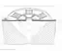
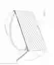
FIG. 5 is a side perspective view, partly in section, of a single nozzle arrangement constructed in accordance with the preferred embodiments;
FIGS. 6-13 are side perspective views, partly in section, illustrating the manufacturing steps of the preferred embodiments;
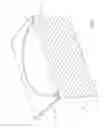
FIG. 14 illustrates an array of ink jet nozzles formed in accordance with the manufacturing procedures of the preferred embodiment;
FIG. 15 provides a legend of the materials indicated in FIGS. 16 to 23; and
FIG. 16 to FIG. 23 illustrate sectional views of the manufacturing steps in one form of construction of a nozzle arrangement in accordance with the invention.
DESCRIPTION OF PREFERRED AND OTHER EMBODIMENTS
In the preferred embodiment, ink is ejected out of a nozzle chamber via an ink ejection port using a series of radially positioned thermal actuator devices that are arranged about the ink ejection port and are activated to pressurize the ink within the nozzle chamber thereby causing the ejection of ink through the ejection port.
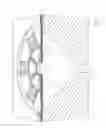
Turning now to FIGS. 1, 2 and 3, there is illustrated the basic operational principles of the preferred embodiment. FIG. 1 illustrates a single nozzle arrangement 1 in its quiescent state. The arrangement 1 includes a nozzle chamber 2 which is normally filled with ink so as to form a meniscus 3 in an ink ejection port 4. The nozzle chamber 2 is formed within a wafer 5. The nozzle chamber 2 is supplied with ink via an ink supply channel 6 which is etched through the wafer 5 with a highly isotropic plasma etching system. A suitable etcher can be the Advance Silicon Etch (ASE) system available from Surface Technology Systems of the United Kingdom.
A top of the nozzle arrangement 1 includes a series of radially positioned actuators 8, 9. These actuators comprise a polytetrafluoroethylene (PTFE) layer and an internal serpentine copper core 17. Upon heating of the copper core 17, the surrounding PTFE expands rapidly resulting in a generally downward movement of the actuators 8, 9. Hence, when it is desired to eject ink from the ink ejection port 4, a current is passed through the actuators 8, 9 which results in them bending generally downwards as illustrated in FIG. 2. The downward bending movement of the actuators 8, 9 results in a substantial increase in pressure within the nozzle chamber 2. The increase in pressure in the nozzle chamber 2 results in an expansion of the meniscus 3 as illustrated in FIG. 2.
The actuators 8, 9 are activated only briefly and subsequently deactivated. Consequently, the situation is as illustrated in FIG. 3 with the actuators 8, 9 returning to their original positions. This results in a general inflow of ink back into the nozzle chamber 2 and a necking and breaking of the meniscus 3 resulting in the ejection of a drop 12. The necking and breaking of the meniscus 3 is a consequence of the forward momentum of the ink associated with drop 12 and the backward pressure experienced as a result of the return of the actuators 8, 9 to their original positions. The return of the actuators 8,9 also results in a general inflow of ink from the channel 6 as a result of surface tension effects and, eventually, the state returns to the quiescent position as illustrated in FIG. 1.
FIGS. 4(a) and 4(b) illustrate the principle of operation of the thermal actuator. The thermal actuator is preferably constructed from a material 14 having a high coefficient of thermal expansion. Embedded within the material 14 are a series of heater elements 15 which can be a series of conductive elements designed to carry a current. The conductive elements 15 are heated by passing a current through the elements 15 with the heating resulting in a general increase in temperature in the area around the heating elements 15. The position of the elements 15 is such that uneven heating of the material 14 occurs. The uneven increase in temperature causes a corresponding uneven expansion of the material 14. Hence, as illustrated in FIG. 4(b), the PTFE is bent generally in the direction shown.
In FIG. 5, there is illustrated a side perspective view of one embodiment of a nozzle arrangement constructed in accordance with the principles previously outlined. The nozzle chamber 2 is formed with an isotropic surface etch of the wafer 5. The wafer 5 can include a CMOS layer including all the required power and drive circuits. Further, the actuators 8, 9 each have a leaf or petal formation which extends towards a nozzle rim 28 defining the ejection port 4. The normally inner end of each leaf or petal formation is displaceable with respect to the nozzle rim 28. Each activator 8, 9 has an internal copper core 17 defining the element 15. The core 17 winds in a serpentine manner to provide for substantially unhindered expansion of the actuators 8, 9. The operation of the actuators 8, 9 is as illustrated in FIG. 4(a) and FIG. 4(b) such that, upon activation, the actuators 8 bend as previously described resulting in a displacement of each petal formation away from the nozzle rim 28 and into the nozzle chamber 2. The ink supply channel 6 can be created via a deep silicon back edge of the wafer 5 utilizing a plasma etcher or the like. The copper or aluminium core 17 can provide a complete circuit. A central arm 18 which can include both metal and PTFE portions provides the main structural support for the actuators 8, 9.
Turning now to FIG. 6 to FIG. 13, one form of manufacture of the nozzle arrangement 1 in accordance with the principles of the preferred embodiment is shown. The nozzle arrangement 1 is preferably manufactured using microelectromechanical (MEMS) techniques and can include the following construction techniques:
As shown initially in FIG. 6, the initial processing starting material is a standard semi-conductor wafer 20 having a complete CMOS level 21 to a first level of metal. The first level of metal includes portions 22 which are utilized for providing power to the thermal actuators 8, 9.
The first step, as illustrated in FIG. 7, is to etch a nozzle region down to the silicon wafer 20 utilizing an appropriate mask.
Next, as illustrated in FIG. 8, a 2 μm layer of polytetrafluoroethylene (PTFE) is deposited and etched so as to define vias 24 for interconnecting multiple levels.
Next, as illustrated in FIG. 9, the second level metal layer is deposited, masked and etched to define a heater structure 25. The heater structure 25 includes via 26 interconnected with a lower aluminium layer.
Next, as illustrated in FIG. 10, a further 2 μm layer of PTFE is deposited and etched to the depth of 1 μm utilizing a nozzle rim mask to define the nozzle rim 28 in addition to ink flow guide rails 29 which generally restrain any wicking along the surface of the PTFE layer. The guide rails 29 surround small thin slots and, as such, surface tension effects are a lot higher around these slots which in turn results in minimal outflow of ink during operation.
Next, as illustrated in FIG. 11, the PTFE is etched utilizing a nozzle and actuator mask to define a port portion 30 and slots 31 and 32.
Next, as illustrated in FIG. 12, the wafer is crystallographically etched on a <111> plane utilizing a standard crystallographic etchant such as KOH. The etching forms a chamber 33, directly below the port portion 30.
In FIG. 13, the ink supply channel 34 can be etched from the back of the wafer utilizing a highly anisotropic etcher such as the STS etcher from Silicon Technology Systems of United Kingdom. An array of ink jet nozzles can be formed simultaneously with a portion of an array 36 being illustrated in FIG. 14. A portion of the printhead is formed simultaneously and diced by the STS etching process. The array 36 shown provides for four column printing with each separate column attached to a different colour ink supply channel being supplied from the back of the wafer. Bond pads 37 provide for electrical control of the ejection mechanism.
In this manner, large pagewidth printheads can be fabricated so as to provide for a drop-on-demand ink ejection mechanism.
One form of detailed manufacturing process which can be used to fabricate monolithic ink jet printheads operating in accordance with the principles taught by the present embodiment can proceed utilizing the following steps:
-
- 1. Using a double-sided polished wafer 60, complete a 0.5 micron, one poly, 2 metal CMOS process 61. This step is shown in FIG. 16. For clarity, these diagrams may not be to scale, and may not represent a cross section though any single plane of the nozzle. FIG. 15 is a key to representations of various materials in these manufacturing diagrams, and those of other cross referenced ink jet configurations.
- 2. Etch the CMOS oxide layers down to silicon or second level metal using Mask 1. This mask defines the nozzle cavity and the edge of the chips. This step is shown in FIG. 16.
- 3. Deposit a thin layer (not shown) of a hydrophilic polymer, and treat the surface of this polymer for PTFE adherence.
- 4. Deposit 1.5 microns of polytetrafluoroethylene (PTFE) 62.
- 5. Etch the PTFE and CMOS oxide layers to second level metal using Mask 2. This mask defines the contact vias for the heater electrodes. This step is shown in FIG. 17.
- 6. Deposit and pattern 0.5 microns of gold 63 using a lift-off process using Mask 3. This mask defines the heater pattern. This step is shown in FIG. 18.
- 7. Deposit 1.5 microns of PTFE 64.
- 8. Etch 1 micron of PTFE using Mask 4. This mask defines the nozzle rim 65 and the rim at the edge 66 of the nozzle chamber. This step is shown in FIG. 19.
- 9. Etch both layers of PTFE and the thin hydrophilic layer down to silicon using Mask 5. This mask defines a gap 67 at inner edges of the actuators, and the edge of the chips. It also forms the mask for a subsequent crystallographic etch. This step is shown in FIG. 20.
- 10. Crystallographically etch the exposed silicon using KOH. This etch stops on <111> crystallographic planes 68, forming an inverted square pyramid with sidewall angles of 54.74 degrees. This step is shown in FIG. 21.
- 11. Back-etch through the silicon wafer (with, for example, an ASE Advanced Silicon Etcher from Surface Technology Systems) using Mask 6. This mask defines the ink inlets 69 which are etched through the wafer. The wafer is also diced by this etch. This step is shown in FIG. 22.
- 12. Mount the printheads in their packaging, which may be a molded plastic former incorporating ink channels which supply the appropriate color ink to the ink inlets 69 at the back of the wafer.
- 13. Connect the printheads to their interconnect systems. For a low profile connection with minimum disruption of airflow, TAB may be used. Wire bonding may also be used if the printer is to be operated with sufficient clearance to the paper.
- 14. Fill the completed print heads with ink 70 and test them. A filled nozzle is shown in FIG. 23.
The presently disclosed ink jet printing technology is potentially suited to a wide range of printing systems including: color and monochrome office printers, short run digital printers, high speed digital printers, offset press supplemental printers, low cost scanning printers high speed pagewidth printers, notebook computers with inbuilt pagewidth printers, portable color and monochrome printers, color and monochrome copiers, color and monochrome facsimile machines, combined printer, facsimile and copying machines, label printers, large format plotters, photograph copiers, printers for digital photographic “minilabs”, video printers, PHOTO CD (PHOTO CD is a registered trade mark of the Eastman Kodak Company) printers, portable printers for PDAs, wallpaper printers, indoor sign printers, billboard printers, fabric printers, camera printers and fault tolerant commercial printer arrays.
It would be appreciated by a person skilled in the art that numerous variations and/or modifications may be made to the present invention as shown in the specific embodiments without departing from the spirit or scope of the invention as broadly described. The present embodiments are, therefore, to be considered in all respects to be illustrative and not restrictive.
Claims
We claim:1. A printhead for an inkjet printer, the printhead comprising:
a wafer defining a plurality of nozzle chambers and a plurality of ink supply channel in fluid communication with the plurality of nozzle chambers for supplying the plurality of nozzle chambers with ink;
an ink ejection port associated with each nozzle chamber; and
a plurality of actuators associated with each nozzle chamber, the plurality of actuators each including a petal formation, wherein
a plurality of petal formations are arranged around an ink ejection port of each nozzle chamber to annularly surround the ink ejection port, and
each actuator is operable to displace a respective petal formation into the nozzle chamber.
2. A printhead as claimed in claim 1, wherein each actuator comprises an electrically conductive heater element formed in a layer of a plastics material, the heater element being positioned in the plastics material to cause uneven heating, and thereby uneven expansion, of the plastics material, whereby the actuator is displaced into the nozzle chamber.
3. A printhead as claimed in claim 2, wherein each heater element is formed in a serpentine arrangement in the plastics material.
4. A printhead as claimed in claim 2, wherein the plastics material is a polytetrafluoroethylene (PTFE) layer, and the heater element is an internal serpentine copper core formed in the PTFE layer.
5. A printhead as claimed in claim 1, wherein bridges extend radially from a rim defining the ink ejection ports and between adjacent actuators.
Images & Drawings included:


Sources:
- United States Patent and Trademark Office - verify current appl. status at the USPTO↗
Recent applications in this class:
- » 20250269646 2025-08-28
LIQUID JET HEAD AND LIQUID JET RECORDING APPARATUS - » 20220339937 2022-10-27
Ink-jet head - » 20220242122 2022-08-04
Thermal bend actuator having improved lifetime - » 20200276817 2020-09-03
Liquid ejecting unit and liquid ejecting apparatus - » 20180207934 2018-07-26
INKJET PRINTING METHOD, AND ASSEMBLY FOR CARRYING OUT THE METHOD - » 20170341395 2017-11-30
Liquid ejecting apparatus - » 20160339703 2016-11-24
Thermal inkjet printhead - » 20160288504 2016-10-06
Fluid ejection device for depositing a discrete quantity of fluid onto a surface - » 20160059561 2016-03-03
Address architecture for fluid ejection chip - » 20160059560 2016-03-03
Chip layout to enable multiple heater chip vertical resolutions
Recent applications for this Assignee:
- » 20120141040 2012-06-07
Method of compressing sequence of strokes - » 20120140280 2012-06-07
Electronically transmitted document delivery through interaction with printed document - » 20120118965 2012-05-17
Process for decoding coded data - » 20120111939 2012-05-10
Transaction recordal method - » 20120104089 2012-05-03
Electronic pen for interacting with substrate - » 20120083252 2012-04-05
Messaging via a coded business card and mobile telephone - » 20120062953 2012-03-15
Application for generating interactive document containing advertising material - » 20120057919 2012-03-08
Pen-shaped printing device - » 20120056003 2012-03-08
Substrate having coding pattern encoding Reed-Solomon symbols - » 20120044186 2012-02-23
Handheld display device having processor for rendering display output with real-time virtual transparency and form-filling option