Lead frame for quad flat no-lead package
US20100165596A1
2010-07-01
12/382,881
2009-03-26
✅ Patent granted
US 8,027,153 B2
2011-09-27
-
-
Yuriy Semenenko
2030-05-15
Abstract:
A lead frame for a quad flat no-lead package includes a plurality of units arranged in a matrix manner and each having four comers. Each of the corners extends outwards to define an attaching portion for attachment to a UV tape such that four sides of each of the units won't fly off when the sides are cut off.
Assignee:
- LINGSEN PRECISION INDUSTRIES, LTD 57 🇹🇼 Taichung, Taiwan
Interested in similar patents?
Get notified when new applications in this technology area are published.
Classification:
H01L23/49541 » CPC main
Details of semiconductor or other solid state devices; Arrangements for conducting electric current to or from the solid state body in operation, e.g. leads, terminal arrangements ; Selection of materials therefor consisting of soldered constructions; Lead-frames or other flat leads Geometry of the lead-frame
H01L21/568 » CPC further
Processes or apparatus adapted for the manufacture or treatment of semiconductor or solid state devices or of parts thereof; Manufacture or treatment of semiconductor devices or of parts thereof the devices having at least one potential-jump barrier or surface barrier, e.g. PN junction, depletion layer or carrier concentration layer; Assembly of semiconductor devices using processes or apparatus not provided for in a single one of the subgroups - , e.g. sealing of a cap to a base of a container; Encapsulations, e.g. encapsulation layers, coatings Temporary substrate used as encapsulation process aid
H01L2924/0002 » CPC further
Indexing scheme for arrangements or methods for connecting or disconnecting semiconductor or solid-state bodies as covered by; Technical content checked by a classifier Not covered by any one of groups , and
H01L2924/00 » CPC further
Indexing scheme for arrangements or methods for connecting or disconnecting semiconductor or solid-state bodies as covered by
H05K5/02 IPC
Casings, cabinets or drawers for electric apparatus Details
H05K5/02 IPC
Casings, cabinets or drawers for electric apparatus Details
Description
BACKGROUND OF THE INVENTION
1. Field of the Invention
The present invention relates generally to a lead frame, and more specifically to a lead frame for use in the quad flat no-lead package.
2. Description of the Related Art
In the quad flat no-lead (QFN) package, a chip is bound to each of units of a lead frame, and then an epoxy resin is poured into each of the units to mold the chip. Thereafter, an operator will attach a UV tape to the back of the lead frame, and then place the lead frame on a ceramic plate for cutting the units.
FIG. 1 shows a square unit 10 of a lead frame according to a prior art, having four right-angled comers 12. Because the contact areas between four sides 14 of the unit 10 located at the corner of the lead frame and the UV tape are insufficient, the sides 14 of the unit 10 may easily fly off under the action of a cutting blade rotating in high speed and a high-pressure water column during cutting process of the unit 10, probably causing the cutting blade and the chip to be damaged by the flying sides 14.
In order to eliminate the above-mentioned drawback, some operators will attach another UV tape to the sides 14 of the unit 10 located at the corner of the lead frame, but the operation time, manpower and material costs will be increased due to the extra UV tape.
SUMMARY OF THE INVENTION
The present invention has been accomplished in view of the above-noted circumstances. It is one objective of the present invention to provide a lead frame that can increase the area of each of units attaching a UV tape.
It is another objective of the present invention to provide a lead frame that can increase mold area.
To achieve these objectives of the present invention, the lead frame comprises a plurality of units arranged in a matrix manner and each having four comers. Each of the comers extends outwards to define an attaching portion for attachment to a UV tape.
Accordingly, the area to which the UV tape is attached and the area into which the resin is poured can be increased through the attaching portions so as to prevent the sides of the unit from flying off during the cutting process.
Further scope of applicability of the present invention will become apparent from the detailed description given hereinafter. However, it should be understood that the detailed description and specific examples, while indicating preferred embodiments of the invention, are given by way of illustration only, since various changes and modifications within the spirit and scope of the invention will become apparent to those skilled in the art from this detailed description.
BRIEF DESCRIPTION OF THE DRAWINGS
The present invention will become more fully understood from the detailed description given herein below and the accompanying drawings which are given by way of illustration only, and thus are not limitative of the present invention, and wherein:
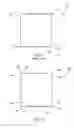
FIG. 1 is a schematic drawing of a unit of a lead frame according to a prior art;
FIG. 2 is a schematic drawing of a unit of a lead frame according to a preferred embodiment of the present invention, and
FIG. 3 is a schematic drawing of a part of a lead frame according to the preferred embodiment of the present invention.
DETAILED DESCRIPTION OF THE INVENTION
As shown in FIGS. 2 and 3, a lead frame 20 in accordance with a preferred embodiment of the present invention comprises a plurality of units 30 arranged in a matrix manner. A cutting line 40 is defined between two adjacent units 30.
The units 30 each have four comers, each of which extends outwards and curvedly to define a curved attaching portion 32 for attachment of a UV tape. The periphery of each of the attaching portions 32 doesn't exceed the cutting line 40, and the attaching portion 32 is not limited to the curved shape.
By means of the extended attaching portions 32, the resin can be poured into the attaching portions 32 such that the mold area can be increased; and further, the contact areas between the sides 34 of the unit 30 located at the corner of the lead frame 20 and the UV tape are sufficient to ensure that the sides 34 won't fly off under the action of a high-speed rotating blade and a high-pressure water column when the sides 34 are cut off, thereby preventing the blade and the chip from damage caused by the flying sides 34.
The invention being thus described, it will be obvious that the same may be varied in many ways. Such variations are not to be regarded as a departure from the spirit and scope of the invention, and all such modifications as would be obvious to one skilled in the art are intended to be included within the scope of the following claims.
Claims
What is claimed is:1. A lead frame comprising:
a plurality of units arranged in a matrix manner and each having four comers, the comers each extending outwards to define an attaching portion for attachment to a UV tape.
2. The lead frame as claimed in claim 1, wherein the attaching portions each have a curved shape.
3. The lead frame as claimed in claim 1, wherein the attaching portions each have a periphery that doesn't exceed a cutting line defined between two adjacent said units.
Images & Drawings included:


Sources:
- United States Patent and Trademark Office - verify current appl. status at the USPTO↗
Similar patent applications:
Recent applications in this class:
- » 20250285945 2025-09-11
SEMICONDUCTOR DEVICE INCLUDING A LEAD AND A SEALING RESIN - » 20250273541 2025-08-28
INTERDIGITATED CANTILEVER LEAD FRAME IN CHIP-ON-LEAD PACKAGE DESIGN - » 20250266330 2025-08-21
SEMICONDUCTOR DEVICE - » 20250246520 2025-07-31
INTEGRATED CIRCUIT PACKAGE WITH PACKAGE RESISTOR - » 20250233055 2025-07-17
ELECTRONIC DEVICE PACKAGING WITH GALVANIC ISOLATION - » 20250201675 2025-06-19
SEMICONDUCTOR PACKAGE WITH WETTABLE FLANK AND RELATED METHODS - » 20250201674 2025-06-19
Engineered Interconnect Structures for Enhanced Bonding Strength - » 20250183129 2025-06-05
THERMAL ENHANCED ELECTRONIC DEVICE PACKAGE - » 20250174526 2025-05-29
SEMICONDUCTOR PACKAGE - » 20250167080 2025-05-22
METHOD OF FORMING A PACKAGED SEMICONDUCTOR DEVICE HAVING ENHANCED WETTABLE FLANK AND STRUCTURE
Recent applications for this Assignee:
- » 20220148887 2022-05-12
Chip packaging method - » 20190265118 2019-08-29
Pressure sensor package - » 20190198406 2019-06-27
Substrate and package module including the same - » 20180190858 2018-07-05
Package structure of long-distance sensor and packaging method of the same - » 20180190857 2018-07-05
Packaging method of long-distance sensor - » 20180190856 2018-07-05
Package structure of long-distance sensor and packaging method of the same - » 20180063646 2018-03-01
MEMS microphone package - » 20180063615 2018-03-01
MEMS microphone package - » 20180063614 2018-03-01
Microphone package structure - » 20160365339 2016-12-15
Optical module integrated package