Heat transfer tubes having dimples arranged between adjacent fins
US20100186443A1
2010-07-29
12/358,804
2009-01-23
✅ Patent granted
US 8,281,564 B2
2012-10-09
-
-
William H Rodriguez | Carlos A Rivera
2031-08-12
Abstract:
A combined cycle power plant includes a first generator driven by a gas turbine for generating electricity. The combined cycle power plant further includes a heat recovery steam generator disposed to receive exhaust gas from the gas turbine. The heat recovery steam generator includes an evaporator having tubes receptive to water flow therethrough. The tubes are disposed to be exposed to the exhaust gas, such that a flow of the exhaust gas passes around the tubes transfers heat from the exhaust gas to the tubes and thereby the water flowing through the tubes sufficient for the water to evaporate into steam. The tubes each having an outer surface with a plurality of deformations formed therein sufficient to introduce turbulence in the flow of the exhaust gas for enhancing heat transfer from the exhaust gas to the tubes.
Inventors:
- Hua Zhang 109 🇺🇸 Greer, SC, United States
- Sal Albert Leone 6 🇺🇸 Scotia, NY, United States
- Thomas Francis Taylor 6 🇺🇸 Greenville, SC, United States
Assignee:
- GENERAL ELECTRIC COMPANY 28,775 🇺🇸 Schenectady, NY, United States
Interested in similar patents?
Get notified when new applications in this technology area are published.
Classification:
F28F13/187 » CPC main
Arrangements for modifying heat-transfer, e.g. increasing, decreasing by applying coatings, e.g. radiation-absorbing, radiation-reflecting; by surface treatment, e.g. polishing; Heat-exchange surfaces provided with microstructures or with porous coatings especially adapted for evaporator surfaces or condenser surfaces, e.g. with nucleation sites
F01K23/10 » CPC further
Plants characterised by more than one engine delivering power external to the plant, the engines being driven by different fluids the engine cycles being thermally coupled combustion heat from one cycle heating the fluid in another cycle with exhaust fluid of one cycle heating the fluid in another cycle
F22B37/101 » CPC further
Component parts or details of steam boilers applicable to more than one kind or type of steam boiler; Water tubes; Accessories therefor Tubes having fins or ribs
F22B37/12 » CPC further
Component parts or details of steam boilers applicable to more than one kind or type of steam boiler; Water tubes; Accessories therefor Forms of water tubes, e.g. of varying cross-section
F28F1/12 » CPC further
Tubular elements; Assemblies of tubular elements; Tubular elements and assemblies thereof with means for increasing heat-transfer area, e.g. with fins, with projections, with recesses the means being only outside the tubular element
F28F13/02 » CPC further
Arrangements for modifying heat-transfer, e.g. increasing, decreasing by influencing fluid boundary
F28D2021/0071 » CPC further
Heat-exchange apparatus not covered by any of the groups - ; Other heat exchangers for particular applications; Heat exchange systems not otherwise provided for for refrigerant cycles Evaporators
F28F3/044 » CPC further
Plate-like or laminated elements; Assemblies of plate-like or laminated elements; Elements or assemblies thereof with means for increasing heat-transfer area, e.g. with fins, with recesses, with corrugations the means being integral with the element in the form of local deformations of the element the deformations being pontual, e.g. dimples
Y02E20/16 » CPC further
Combustion technologies with mitigation potential Combined cycle power plant [CCPP], or combined cycle gas turbine [CCGT]
Y02E20/16 » CPC further
Combustion technologies with mitigation potential Combined cycle power plant [CCPP], or combined cycle gas turbine [CCGT]
Y02P80/15 » CPC further
Climate change mitigation technologies for sector-wide applications; Efficient use of energy, e.g. using compressed air or pressurized fluid as energy carrier On-site combined power, heat or cool generation or distribution, e.g. combined heat and power [CHP] supply
Y02P80/15 » CPC further
Climate change mitigation technologies for sector-wide applications; Efficient use of energy, e.g. using compressed air or pressurized fluid as energy carrier On-site combined power, heat or cool generation or distribution, e.g. combined heat and power [CHP] supply
F25B39/02 IPC
Evaporators; Condensers Evaporators
F28F1/10 IPC
Tubular elements; Assemblies of tubular elements Tubular elements and assemblies thereof with means for increasing heat-transfer area, e.g. with fins, with projections, with recesses
F02C6/00 IPC
Plural gas-turbine plants; Combinations of gas-turbine plants with other apparatus ; Adaptations of gas- turbine plants for special use
F02G1/00 IPC
Hot gas positive-displacement engine plants
F02G3/00 IPC
Combustion-product positive-displacement engine plants
F01K23/06 IPC
Plants characterised by more than one engine delivering power external to the plant, the engines being driven by different fluids the engine cycles being thermally coupled combustion heat from one cycle heating the fluid in another cycle
F22B23/06 IPC
Water-tube boilers built-up from sets of spaced double-walled water tubes of return type in unilateral abutting connection with a boiler drum or with a header box, i.e. built-up from Field water tubes comprising an inner tube arranged within an outer unilaterally-closed tube Component parts thereof, e.g. Field water tubes
F22B37/10 IPC
Component parts or details of steam boilers applicable to more than one kind or type of steam boiler Water tubes; Accessories therefor
F28D1/04 IPC
Heat-exchange apparatus having stationary conduit assemblies for one heat-exchange medium only, the media being in contact with different sides of the conduit wall, in which the other heat-exchange medium is a large body of fluid, e.g. domestic or motor car radiators with heat-exchange conduits immersed in the body of fluid with tubular conduits
Description
BACKGROUND OF THE INVENTION
This invention relates generally to improved heat transfer by heat transfer tubes in a heat recovery steam generator of a combined cycle power plant. More particularly, this invention relates to deformations in the outer surface of the heat transfer tubes to enhance heat transfer within a heat recovery steam generator, while also decreasing pressure drop within the heat recovery steam generator.
Combined cycle power plants include a heat recovery steam generator for recovering heat from the exhaust of a gas turbine to generate heat for powering a steam turbine, as is known. The heat recovery steam generator currently utilizes a plurality of tubes that transfer thermal energy from the gas turbine exhaust to water/steam inside the tubes thereby generating steam or boosting steam temperature. The tubes have solid serrated fins to promote heat transfer. Water/steam within the tubes is heated by the passing exhaust gases to generate steam or super heated steam for powering the steam turbine of the combined cycle power plant. However, a pressure drop occurs on the air side of the heat recovery steam generator, which adversely impacts performance of gas turbines. Increasing the number of fins to improve heat transfer at the tubes, may result in an undesirable increase in the pressure drop. This is because the fins seek to enhance heat transfer by simply increasing surface area, which results in increased drag, therefore, pressure drop increase. Most of the improvement in heat transfer coefficient using fins is undermined by the increased pressure drop. For example, with serrated fins that result in an increase in the heat transfer coefficient of 10%, the cost of the pressure drop is 25%.
The heat recovery steam generator is a significant portion of the overall cost of the combined cycle power plant. By improving heat transfer efficiency within the heat recovery steam generator, the combined cycle power plant cost can be reduced.
BRIEF DESCRIPTION OF THE INVENTION
According to one aspect of the invention, an evaporator of a heat recovery steam generator includes at least one tube. The at least one tube has an outer surface with a plurality of deformations formed therein sufficient to introduce turbulence in a flow of a gas around the at least one tube for enhancing heat transfer from the gas to the at least one tube.
According to another aspect of the invention, a construction method for an evaporator having at least one tube of a heat recovery steam generator includes forming a plurality of deformations in an outer surface of the at least one tube sufficient to introduce turbulence in a flow of a gas around the at least one tube for enhancing heat transfer from the gas to the at least one tube.
According to yet another aspect of the invention, a combined cycle power plant includes a first generator driven by a gas turbine for generating electricity. During operation of the gas turbine exhaust gas is generated. The combined cycle power plant further includes a heat recovery steam generator disposed to receive the exhaust gas from the gas turbine. The heat recovery steam generator includes an evaporator having at least one tube receptive to water flow there through. The at least one tube is disposed to be exposed to the exhaust gas, such that a flow of the exhaust gas passes around the at least one tube transfers heat from the exhaust gas to the at least one tube and thereby the water flowing through the at least one tube sufficient for the water to evaporate into steam. The at least one tube having an outer surface with a plurality of deformations formed therein sufficient to introduce turbulence in the flow of the exhaust gas for enhancing heat transfer from the exhaust gas to the at least one tube. The combined cycle power plant also includes a second generator driven by a steam turbine for generating electricity. The steam turbine is receptive to the steam from the heat recovery steam generator for driving the steam turbine.
These and other advantages and features will become more apparent from the following description taken in conjunction with the drawings.
BRIEF DESCRIPTION OF THE DRAWINGS
The subject matter which is regarded as the invention is particularly pointed out and distinctly claimed in the claims at the conclusion of the specification. The foregoing and other features and advantages of the invention are apparent from the following detailed description taken in conjunction with the accompanying drawings in which:
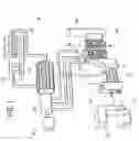
FIG. 1 is a schematic diagram of a combined cycle power plant;
FIG. 2 is a perspective view of tubes in a heat recovery steam generator, the tubes being exposed to the gas turbine exhaust to transfer thermal energy from the gas turbine exhaust to water inside the tubes thereby generating steam;
FIG. 3 is a diagrammatic cross-sectional view of a tube illustrating airflow thereabout in accordance with the prior art;
FIG. 4 is a diagrammatic cross-sectional view of a tube illustrating airflow thereabout in accordance with the present invention;
FIG. 5 is a velocity profile diagram of the airflow about the tube of FIG. 3;
FIG. 6 is a velocity profile diagram of the airflow about the tube of FIG. 4; and
FIG. 7 is a plot of pressure drop reduction of the airflow about the tube of FIG. 4.
The detailed description explains embodiments of the invention, together with advantages and features, by way of example with reference to the drawings.
DETAILED DESCRIPTION OF THE INVENTION
Referring to FIG. 1 a combined cycle power plant is generally shown at 10. In a first cycle of the combined cycle power plant 10 a gas turbine 12 is connected to a generator 14 for generating electricity. Air is ingested into the gas turbine 12 through an air intake 16 and fuel is provided to the gas turbine at intakes 18. The fuel is burned to drive the gas turbine 12 and the resulting combustion gas is exhausted. The gas turbine 12 drives the generator 14, which generates the electricity. In a simple cycle power plant the hot exhaust gas would be lost, however in the combined cycle power plant 10 it is utilized to drive a second cycle.
In a second cycle of the combined cycle power plant 12 the hot exhaust gas is captured and directed into a heat recovery steam generator 20. The heat recovery steam generator 20 utilizes a high pass evaporator 22 and a low pass evaporator 24, which have a plurality of tubes (not shown) that are exposed to the hot exhaust gas from the gas turbine 12. Water is fed through the tubes, as is discussed below. The exhaust gas heats the tubes, which transfers the heat to the water causing the water to evaporate into steam. This steam is delivered to a steam turbine 28 to drive the steam turbine 28, which in-turn drives a generator 30 for generating electricity. The steam passing through the steam turbine 28 is delivered to a steam condenser 32, where it is condensed back to water and delivered to a reservoir 26. The water at reservoir 26 is cooled by a cooling tower 33, with the cooled water being delivered to the steam condenser 32 to condense the steam back to the liquid state. Water at the steam condenser 32 is also delivered to the heat recovery steam generator 20 where it is fed through the tubes, this water is not cooled.
The heat recovery steam generator 20 has an intake duct 34 which receives exhaust gas from the gas turbine 12 and directs the exhaust gas into the high pass evaporator 22 and then the low pass evaporator 24. The evaporators include the tubes (not shown) for evaporating liquid water passing there through into steam. The exhausted gas is then vented to a stack 40.
Referring to FIG. 2, tubes 42 are arranged in an array between an intake manifold 44 and exit manifold 46. The tubes 42 each have a plurality of solid serrated fins 47 extending outwardly therefrom, which seek to promote heat transfer by simply increasing surface area. Liquid water is delivered to intake manifold 44 by a pipe 48 and is distributed to the tubes 42 by the manifold 44. Exhaust gas, as indicated by lines 50, passes around the tubes 42, whereby the tubes 42 are heated. Liquid water within tubes 42 when sufficiently heated produces steam, which enters the exit manifold 46 and exits the heat recovery steam generator 20 via a pipe 49. Improved heat transfer from the exhaust gas to the tubes 42 is desired. As mentioned above, the heat recovery steam generator 20 is a significant contributor to overall efficiency and cost of the combined cycle power plant 10. Overall heat transfer efficiency can be improved, whereby plant cost can be reduced.
Referring to FIG. 3, a tube 42′ of the prior art is show, which has a generally smooth outer surface 52 and the aforementioned fins (not shown). The exhaust gas flow, illustrated by lines 54, is moving towards the tube 42′, as it reaches the outer surface 52 of the tube 42′ it comes into contact with a laminar boundary layer, designated 56. The laminar boundary layer 56 is the layer where the exhaust gas flow hits and follows the outer surface 52 of the tube 42′ until the exhaust gas flow reaches a point of separation, designated 58. At which point the exhaust gas flow will continue along its path apart from the tube 42′. The exhaust gas flow will then produce a wake, designated 60, past the point of separation 58, which consists of vortexes 62. These vortexes 62 create a low-pressure zone within the wake 60 that is inefficient for heat transfer and a major contributor for pressure drop.
Referring now to FIG. 4, a tube 42″ of the present invention is show. The tube 42″ has a roughed outer surface 66 and the aforementioned fins (not shown). The roughed outer surface 66 is formed by deforming the outer surfaces with indentations or dimples 68. These deformations, i.e., indentations or dimples 68, may be configured in a pattern to achieve desired flow at the outer surface 66. The exhaust gas flow, illustrated by lines 70, is moving towards the tube 42″, as it reaches the outer surface 66 of the tube 42″ it comes into contact with a laminar boundary layer, designated 72. The laminar boundary layer 72 is the layer where the exhaust gas flow hits and follows the outer surface 66 of the tube 42″ until the exhaust gas flow reaches a point of separation, designated 74. At which point the exhaust gas flow interacts with the deformations 68 introducing turbulence in the exhaust gas flow. The turbulence promotes a transition from the laminar boundary layer 72 to a turbulent boundary layer 76. The turbulent boundary layer 76 is an area oriented further back on the tube 42″ from the point of initial exhaust gas flow contact. In the turbulent boundary layer 76 the deformations 68 create the turbulence, which helps the exhaust gas flow remain at the surface 66 of the tube 42″. Thusly, preventing early separation as was seen in tube 42′ of FIG. 3. The exhaust gas flow will continue along its path apart from the tube 42″. The exhaust gas flow will then produce a wake, designated 78, past the point of separation 74, which consists of vortexes 80. This results in a low-pressure zone or area that is significantly smaller than the one created by the tube 42′ of FIG. 3, which consequently results in a decrease in the pressure drop and a increase in heat transfer between the exhaust gas and the tube 42″.
Referring to FIG. 5 a velocity profile diagram of airflow about the tube 42′ is shown. The velocity profile shows a high velocity vector at the outer surface 52 of tube 42′, which is inefficient for heat transfer.
Referring to FIG. 6 a velocity profile diagram of airflow about the tube 42″ is shown. The velocity profile shows a significantly lower velocity vector, as compared to the velocity vector shown in FIG. 5, at the outer surface 52 of tube 42″, which is more efficient for heat transfer.
Referring now to FIG. 7 a plot of pressure drop reduction of the airflow about the tube 42″ is generally shown, wherein the y-axis is Pressure Drop in Pascals and the x-axis is Roughness in inches. The slope of the line demonstrates that as the size of the deformations 68 increases there is a smaller pressure drop, which is favorable to the heat transfer between the exhaust gas and the tube 42″, and, thusly the overall efficiency of the combined cycle power plant.
While the invention has been described in detail in connection with only a limited number of embodiments, it should be readily understood that the invention is not limited to such disclosed embodiments. Rather, the invention can be modified to incorporate any number of variations, alterations, substitutions or equivalent arrangements not heretofore described, but which are commensurate with the spirit and scope of the invention. Additionally, while various embodiments of the invention have been described, it is to be understood that aspects of the invention may include only some of the described embodiments. Accordingly, the invention is not to be seen as limited by the foregoing description, but is only limited by the scope of the appended claims.
Claims
1. An evaporator of a heat recovery steam generator, the evaporator having at least one tube, the at least one tube having an outer surface with a plurality of deformations formed therein sufficient to introduce turbulence in a flow of a gas around the at least one tube for enhancing heat transfer from the gas to the at least one tube.
2. The evaporator of claim 1 wherein the deformations comprise dimples.
3. The evaporator of claim 1 wherein the deformations are arranged in a pattern.
4. The evaporator of claim 2 wherein the dimples are arranged in a pattern.
5. A construction method for an evaporator of a heat recovery steam generator, the evaporator having at least one tube, the construction method comprising:
forming a plurality of deformations in an outer surface of the at least one tube sufficient to introduce turbulence in a flow of a gas around the at least one tube for enhancing heat transfer from the gas to the at least one tube.
6. The construction method of claim 5 wherein the deformations comprise dimples.
7. The construction method of claim 5 wherein the deformations are arranged in a pattern.
8. The construction method of claim 6 wherein the dimples are arranged in a pattern.
9. A combined cycle power plant comprising;
a gas turbine;
a first generator driven by the gas turbine for generating electricity, wherein during operation of the gas turbine exhaust gas is generated;
a heat recovery steam generator disposed to receive the exhaust gas from the gas turbine, the heat recovery steam generator including an evaporator having at least one tube receptive to water flow there through, the at least one tube disposed to be exposed to the exhaust gas, wherein a flow of the exhaust gas passes around the at least one tube to transfer heat from the exhaust gas to the at least one tube and thereby the water flowing through the at least one tube sufficient for the water to evaporate into steam, the at least one tube having an outer surface with a plurality of deformations formed therein sufficient to introduce turbulence in the flow of the exhaust gas for enhancing heat transfer from the exhaust gas to the at least one tube;
a steam turbine receptive to the steam from the heat recovery steam generator for driving the steam turbine; and
a second generator driven by the steam turbine for generating electricity.
10. The combined cycle power plant of claim 9 wherein the deformations comprise dimples.
11. The combined cycle power plant of claim 9 wherein the deformations are arranged in a pattern.
12. The combined cycle power plant of claim 10 wherein the dimples are arranged in a pattern.
13. The combined cycle power plant of claim 9 wherein the at least one tube comprises a plurality of tubes arranged between an intake manifold and exit manifold.
14. The combined cycle power plant of claim 9 wherein the tubes each has a plurality of solid serrated fins extending outwardly therefrom.
Images & Drawings included:


Sources:
- United States Patent and Trademark Office - verify current appl. status at the USPTO↗
Recent applications in this class:
- » 20250060176 2025-02-20
DUAL-CHANNEL FLOW BOILING SYSTEM WITH FUNCTIONALIZED SURFACES - » 20240295371 2024-09-05
IMMERSION-TYPE LIQUID COOLING HEAT DISSIPATION STRUCTURE - » 20240175649 2024-05-30
Heat Exchange Tube and Manufacturing Method Therefor - » 20240159480 2024-05-16
HEAT EXCHANGER MEMBER, HEAT EXCHANGER, AIR CONDITIONER INDOOR UNIT, AIR CONDITIONER OUTDOOR UNIT, AND REFRIGERATOR - » 20240102750 2024-03-28
Droplet Ejecting Coatings - » 20230280115 2023-09-07
Amphiphilic Minichannel Surface Structures to Enhance Heat Transfer Coefficient - » 20230235977 2023-07-27
Nanostructure Coating Materials and Methods of Use Thereof - » 20220390191 2022-12-08
Droplet ejecting coatings - » 20220228819 2022-07-21
HEAT EXCHANGER MEMBER, HEAT EXCHANGER, AND COOLING SYSTEM - » 20220074686 2022-03-10
Droplet ejecting coatings
Recent applications for this Assignee:
- » 20250250942 2025-08-07
Overall Engine Efficiency Rating for Turbomachine Engines - » 20250243827 2025-07-31
MULTIPLE-FLOW AIRCRAFT TURBINE ENGINE - » 20250229333 2025-07-17
SYSTEMS AND METHODS FOR SMOOTHING A CONTOUR OF AN OBJECT FORMED DURING ADDITIVE MANUFACTURING - » 20250224115 2025-07-10
TURBINE ENGINE HAVING A COMBUSTION SECTION WITH A FUEL SUPPLY ASSEMBLY - » 20250223929 2025-07-10
UNDUCTED PROPELLER GAS TURBINE COMPRISING A COOLING AIR CHANNEL AND A VARIABLE BLEED VALVE EJECTION CHANNEL - » 20250222519 2025-07-10
ADDITIVE MANUFACTURING SUPPORTS AND METHODS FOR USING SAME IN ADDITIVELY MANUFACTURING PARTS - » 20250215830 2025-07-03
SUSPENSION OF A TRIPLE-FLOW AIRCRAFT TURBINE ENGINE - » 20250215826 2025-07-03
GAS TURBINE ENGINE - » 20250215811 2025-07-03
SYSTEMS AND METHODS FOR ATTACHMENT OF MATERIALS HAVING DIFFERENT THERMAL EXPANSION COEFFICIENTS - » 20250207534 2025-06-26
GAS TURBINE ENGINES AND EPICYCLIC GEARBOXES WITH PLANET GEAR CLEARANCES