Composite cement panel
US20100189953A1
2010-07-29
12/600,635
2008-05-09
✅ Patent granted
US 8,438,806 B2
2013-05-14
WO; PCT/SG2008/000174; 20080509
WO; WO2008/143591; 20081127
Basil Katcheves | Rodney Mintz
Occhiuti Rohlicek & Tsao LLP
2028-10-21
Abstract:
This invention relates to a composite panel for a rooftop surface having a core material board having a top surface and a bottom surface with a plurality of openings through said core material board extending from said top surface to said bottom surface; a rigid outer shell of solid material that encapsulates said core material board; a plurality of supports of said solid material wherein each of said plurality of supports extends through one of said plurality of openings in said core material board; and a plurality of legs on a portion of said rigid outer shell covering said bottom surface of core board material.
Applicant:
Interested in similar patents?
Get notified when new applications in this technology area are published.
Classification:
E04D11/00 » CPC main
Roof covering, as far as not restricted to features covered by only one of groups - ; Roof covering in ways not provided for by groups - , e.g. built-up roofs, elevated load-supporting roof coverings
B28B7/0064 » CPC further
Moulds; Cores; Mandrels Moulds characterised by special surfaces for producing a desired surface of a moulded article, e.g. profiled or polished moulding surfaces
B28B23/0068 » CPC further
Arrangements specially adapted for the production of shaped articles with elements wholly or partly embedded in the moulding material; Production of reinforced objects Embedding lost cores
E04D11/005 » CPC further
Roof covering, as far as not restricted to features covered by only one of groups - ; Roof covering in ways not provided for by groups - , e.g. built-up roofs, elevated load-supporting roof coverings Supports for elevated load-supporting roof coverings
E04F15/02 » CPC further
Flooring Flooring or floor layers composed of a number of similar elements
E04F15/185 » CPC further
Flooring; Separately-laid insulating layers; Other additional insulating measures; Floating floors Underlayers in the form of studded or ribbed plates
Y10T428/24174 » CPC further
Stock material or miscellaneous articles; Structurally defined web or sheet [e.g., overall dimension, etc.] including sheet or component perpendicular to plane of web or sheet
Y10T428/24347 » CPC further
Stock material or miscellaneous articles; Structurally defined web or sheet [e.g., overall dimension, etc.] including aperture; Composite web or sheet including nonapertured component; Keyed From both sides
B32B27/06 IPC
Layered products comprising synthetic resin as the main or only constituent of a layer, next to another layer of a
B32B13/12 IPC
Layered products comprising a a layer of water-setting substance, e.g. concrete, plaster, asbestos cement, or like builders' material comprising such substance as the main or only constituent of a layer, next to another layer of a of synthetic resin
E04C2/288 IPC
Building elements of relatively thin form for the construction of parts of buildings, e.g. sheet materials, slabs, or panels characterised by specified materials composed of materials covered by two or more of groups , , or of materials covered by one of these groups with a material not specified in one of the groups at least one of the materials being insulating composed of insulating material and concrete, stone or stone-like material
B28B1/00 IPC
Producing shaped prefabricated articles from the material
B29C67/24 IPC
Shaping techniques not covered by groups - , or characterised by the choice of material
E04F17/00 IPC
Vertical ducts; Channels, e.g. for drainage
E04B1/70 IPC
Constructions in general; Structures which are not restricted either to walls, e.g. partitions, or floors or ceilings or roofs; Insulation or other protection; Elements or use of specified material therefor Drying or keeping dry, e.g. by air vents
B32B3/26 IPC
Layered products comprising a layer with external or internal discontinuities or unevennesses, or a layer of non-planar form ; Layered products having particular features of form characterised by a particular shape of the outline of the cross-section of a continuous layer; characterised by a layer with cavities or internal voids ; characterised by an apertured layer
E04D3/35 IPC
Roof covering by making use of flat or curved slabs or stiff sheets Roofing slabs or stiff sheets comprising two or more layers, e.g. for insulation
Description
TECHNICAL FIELD
The present invention relates to composite cement panel for use in a roof deck or similar structure, and a fabricating method of the cement panel.
BACKGROUND ART
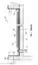
FIG. 1 illustrates a typical construction 100 of a cladding construction system of a concrete roof deck 102. A cement sand base 104 is formed over the roof deck 102, the base 104 being screed to form a slope or slope-to-fall gradient to create a drainage fall into a drain 106 and downpipe 108. A waterproof membrane 110 is laid over the cement sand base 104, interrupted only by downpipe 108, and extending a height 112 of 300 mm up the inside surface of walls 114. Where the deck 102 meets some walls 114, the transition of the waterproof membrane from the horizontal surface to the vertical surface may be effected by use of waterproof filler such as poly foam 116. A thermal insulating layer 118 is constructed on top of the membrane 110, the layer 118 comprising extruded polystyrene insulation board of 50 mm thickness. A separation fleece layer 120 overlies the thermal insulating layer 118. Finally an overlying protective screed concrete layer 122 of 75 mm thickness is provided, comprising 4.5 m by 4.5 m panels separated by joints filled with bituminous compound. Plastering 124 is applied to walls 114.
The thermal insulating material 118 reduces heat transfer through the concrete roof deck 102 into the building below. The protective cement screed 122 protects the thermal insulating material 118 and the waterproofing membrane 110, and bears the human traffic on the roof deck. Such a construction 100 is constructed in-situ on site, with an expansion joint provided at regular intervals.
Construction 100 suffers from a range of problems. The expansion joints in concrete screed layer 122 are a weak point in the construction and a source of leaks. Residual water becomes lodged between the thermal insulating material 118 and the waterproofing membrane 110 after rain. When exposed to heat from the sun, the water expands and evaporates, exerting pressure on the thermal insulating material 118 which in turn exerts pressure onto the protective screed concrete 122. Both the protective screed concrete 122 and thermal insulating material 118 will generally crack due to such stress, leading to leakage and/or “sickness” in the construction 100.
A further problem is that on site cladding construction makes quality control difficult, can cause damage to the waterproofing system, and is subject to the vagaries of inclement weather during construction leading to time delay. In addition, mixing, handling and/or applying concrete slurry on site can be messy and laborious.
Still further, in the event that maintenance is required to the underlying roof deck 102, waterproofing membrane 110 and/or components of the built-up waterproofing system 104, 118, 120, 122, the protective screed 122 and some or all underlying layers need to be destructively removed such as by being cut away, effectively destroying the construction 100. The entire process of building up the waterproofing system must then be repeated to re-establish a waterproof cladding.
Any discussion of documents, acts, materials, devices, articles or the like which has been included in the present specification is solely for the purpose of providing a context for the present invention. It is not to be taken as an admission that any or all of these matters form part of the prior art base or were common general knowledge in the field relevant to the present invention as it existed before the priority date of each claim of this application.
Throughout this specification the word “comprise”, or variations such as “comprises” or “comprising”, will be understood to imply the inclusion of a stated element, integer or step, or group of elements, integers or steps, but not the exclusion of any other element, integer or step, or group of elements, integers or steps.
BRIEF DESCRIPTION OF THE DRAWINGS
FIG. 1 illustrates a typical roof cladding construction;
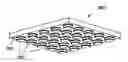
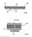
FIG. 2 is a perspective view of a formwork for cement casting for a composite cement panel according to one embodiment of the present invention;
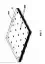
FIG. 3 is a perspective view of a foam board placed in the formwork of FIG. 2 for fabricating a composite cement panel according to one embodiment of the present invention.
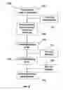
FIG. 4 is a flowchart showing a process for fabricating a cement panel using the formwork of FIG. 2.
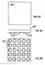
FIG. 5A is a top view of a composite cement panel according to one embodiment of the present invention.
FIG. 5B is a bottom view of FIG. 5A.
FIG. 6A is a front view of FIG. 5A.
FIG. 6B is a cross sectional side view of FIG. 5A.
FIG. 6C is a partially enlarges view of FIG. 6B.
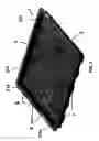
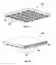
FIG. 7A is a perspective bottom view of FIG. 5A.
FIG. 7B is a partially cross sectional perspective view of FIG. 5A.
DETAILED DESCRIPTION OF THE INVENTION
FIG. 2 shows a formwork 2, made of metal for example, for casting a composite cement panel 800 shown in FIG. 7A. Formwork 2 has an array of recesses 3 formed on the base surface 4. Recesses 3 are positioned spaced apart from each other across the base surface 4 of the formwork 2. Guide abutments 6 are provided on two adjacent inner surfaces 214, 215 of the metal formwork 2. Formwork 2 further includes pins 8 positioned on the bottom surface 4. Pins 8 extend upwardly from the base surface 4 of formwork 2. Formwork 2 ends with an upturn skirting 7 along the peripheral edge, allowing ease of handling the formwork 2 during casting or transportation of the cement panel 800.
FIG. 3 illustrates a light-weight core material board, such as a foam board 200, placed in formwork 2 before the process of cement casting of the composite cement panel 800. Foam board 200 has through holes 202 formed thereon by, for example, drilling, stamping, cutting, punching or pre-made integratedly during a molding process forming the foam board. Through holes 202 are configured such that, when foam board 200 is placed in formwork 2, each through hole faces one recess of formwork 2. When placed in formwork 2, foam board 200 sits on pins 8, leaving a gap between foam board 2 and bottom surface 4 of formwork 2.
FIG. 4 is a flowchart of a process 300 for fabricating a cement panel using the formwork 2 shown in FIG. 2. At step 302, foam board 200 having through holes 2 formed there on, is placed in the formwork 2, with two adjacent sides of the form board acting against a respective guide abutment 6. This way, there is remained a side gap between the periphery of foam board and inner surfaces 214 and 215 of formwork 2.
At step 312 a pre-mixed self-levelling high strength cement grout, with or without concrete hardener or chemical additive, is prepared. At step 306, the cement grout is poured onto foam board 200 and into formwork 2. During this step, cement grout will fill up the round recesses 3 in the formwork 2, the gap between the foam board and the bottom surface 4 of formwork 2, the gap between the periphery of foam board 200 and inner surfaces 214, 215, 216 and 217 of formwork 2, and the holes 202 of the foam board 200. At step 308, the cement grout fills formwork fully, and is trowelled and finished. At step 310 the cement grout is left to dry and harden, hence to form a cement casing 502 encapsulating foam board 200, and form the composite cement panel. At step 314 the formed cement panel is removed from the formwork 2.
Depending the building roof conditions and the finishing requirements, the composite cement panel may be fabricated with a suitable finishing layer on its top surface. For example, at an optional pre-dry finishing step 318, pebbles may be pours onto the top surface of the wet composite cement panel. The pebbles are then attached onto the top surface of the panel, and dried together with the panel. Alternatively, color cement powders may be supplied onto the top surface of the wet composite cement panel and dried together, so as to form a colored finishing layer. Imprints with predetermined patterns may also be formed, by molding or pressing the patterns on the top surface of the composite cement panel. In a further optional after-dry step 320, as an alternative of step 318, the dried composite cement panel may be covered by tiles, wood panels or natural/artificial stones and/or a layer of heat-insulating or waterproof coating.
FIGS. 5A, 5B, 6A, 6B, 6C, 7A and 7B illustrate a composite cement panel 800 produced after step 314 of process 300 (shown in FIG. 4). With reference to FIG. 6A and FIG. 6B, it can be seen that the foam board 200 is encapsulated in the cement casing 502. Also, it can be seen from FIG. 6C that the top portion 204 and bottom portion 206 of the cement casing is bound by portions of cement 520a surrounding the foam board 200 as well as the portions filling the holes 202 of the foam board 200. Portions of cement casing 502 fills in the holes 202 of foam board 200, forming columns 570. These columns 570 increase the strength and rigidity of the cement panel 800, and serve to distribute applied weight, such as foot traffic, to reduce the likelihood of foam board 200 being crushed. Portions of the cement casing filling in the round recess 3 of formwork 2 form legs 220 at the bottom side 250 of the composite cement panel 800. Additionally, the foam board 200 is chemically bonded to the cement casing 502 by additives in the cement grout.
With reference to FIGS. 7A and 7B, legs 220 extend downwardly from the bottom surface 250 of the cement panel 800. When leveled on top the roof top surface of a building, legs 220 rests on the roof top surface, providing a network of multi-directional free-flow paths between the spaces of the legs 220 for draining water along the underside of the cement panel 800. Provision of legs 220 of cylinder shape and multi-directional flow paths reduces trapping of residual water in the cement panel 800, and at the same time allows the water to flow in multiple-directions on the roof top surface level. Thus, better drainage of water can be achieved even in heavy rainfall. By encapsulating the foam board in the cement casing, water or moisture is prevented from penetrating into the panel and wet the foam board, hence the likelihood of the foam board deformation or damage caused by water or moisture content is avoided.
The size and thicknesses of foam boards 200 are kept in appropriate ratio to the size and thickness of the finished cement panel 800 to achieve a satisfactory effect of thermal insulating. In one embodiment, the dimensions of foam board 200 are 18 mm thick by 480 mm width by 480 mm length. Specifications of the one exemplary polystyrene foam board 200 are listed in Table 1 below.
| TABLE 1 |
| Specification of foam board |
| Property | Test Method | Unit(s) | Typical Value(s) |
| Density | kg/m3 | 40~50 | |
| Thermal | ASTM C518: | W/m ° K | 0.02207 |
| Conductivity | 1991 | kcal/mm ° K | 0.01897 |
| 10% Compressive | ASTM D 1621: | N/mm2 | 0.30 |
| Strength (Average) | 2000 | ||
| Flammability | ASTM C635: 91 | cm/min | 10.0 |
| Classification | |||
| (Average burning | |||
| rate) | |||
| Water Absorption | ASTM C272: | % | 0.01 |
| (Average) | 2001 | ||
| Temperature of Hot | ° C. | 40.77 | |
| Surface | |||
| Temperature of | ° C. | 19.95 | |
| Cold Surface | |||
| Mean Temperature | ° C. | 30.36 | |
The composition of an exemplary pre-mixed, self-leveling, high strength cement grout is listed in Table 2 below.
| TABLE 2 |
| Composition of cement grout |
| Name | CAS | Proportion | |
| Portland Cement | 65997-15-1 | 10-60% | |
| Sand (Crystalline Quartz) | 14808-60-7 | 10-60% | |
| Flow Aid, Plasticiser | 0-1% | ||
| Concrete Strengthener Additive | 250 ml | ||
The specification of an exemplary concrete strengthener is listed in Table 3 below.
| TABLE 3 |
| specification of the concrete strengthener |
| Property | Unit | Typical Value | |
| Solid Content | % | >40 | |
| Density | kg/m3 | 1.16 ± 0.04 | |
| Crack Filing | mm | 0.1-2 | |
| Depth of Absorption (for | mm | 1-8 | |
| Grade 20 Concrete) | |||
| Flash Point Waterborne | Not flammable | ||
| Drying Time | hours | 1-3 | |
| Weather Condition | ° C. | 10-50 | |
| UV Resistance | Stable | ||
It will be appreciated by persons skilled in the art that numerous variations and/or modifications may be made to the invention as shown in the specific embodiments without departing from the spirit or scope of the invention as broadly described. The present embodiments are, therefore, to be considered in all respects as illustrative and not restrictive.
Claims
What is claimed is:1. A composite panel for a rooftop surface comprising:
a core material board having a top surface and a bottom surface with a plurality of openings through said core material board extending from said top surface to said bottom surface;
a rigid outer shell of solid material that encapsulates said core material board;
a plurality of supports of said solid material wherein each of said plurality of supports extends through one of said plurality of openings in said core material board; and
a plurality of legs on a portion of said rigid outer shell covering said bottom surface of core board material.
2. The composite panel of claim 1 wherein said plurality of supports are integral to said rigid outer shell.
3. The composite panel of claim 1 wherein each of said plurality of supports is a column.
4. The composite panel of claim 1 further comprising:
a gap between a surface of a structure and a portion of said rigid outer shell over said bottom surface of said core material board created by said plurality of legs supporting said composite panel over said surface of said structure.
5. The composite panel of claim 4 further comprising:
a flow path under said panel in said gap defined by said plurality of legs.
6. The composite panel of claim 4 further comprising:
a plurality of flow paths under said panel in said gap defined by said plurality of legs.
7. The composite panel of claim 1 where in each of said plurality of legs is cylinder shaped.
8. The composite panel of claim 1 wherein said core material board is chemically bonded to said rigid outer shell.
9. The composite panel of claim 1 wherein said core material board comprises:
a polystyrene foam board.
10. The composite panel of claim 1 wherein said rigid outer shell comprises:
a cement mixture.
11. The composite panel of claim 1 wherein each of said plurality of supports is substantially aligned with one of said plurality of legs.
12. The composite panel of claim 1 further comprising:
a covering over a surface of a portion of said rigid outer shell covering said top surface of said core material board.
13. A method for producing a composite panel comprising:
placing a core material board having a top surface, a bottom surface, and a plurality of openings through said core material board from said top surface to said bottom surface in a formwork having a base surface with a plurality of recesses defined in said base surface, a plurality of pins extending upwards from said base surface, and an upturned skirting around a peripheral edge of said base surface wherein said core material board is separated from said base surface by said plurality of pins and is spaced apart from said upturned skirting;
filling said formwork with a viscous material that fills said plurality of recesses, fills said plurality of openings in said core material board and surrounds said core material board in said formwork; and
allowing said viscous material to harden into a rigid outer shell encapsulating said core material board.
14. The method of claim 13 further comprising:
trowelling a top surface of said viscous material to create a smooth surface responsive to pouring said viscous material into said formwork.
15. The method of claim 13 further comprising:
pouring pebbles onto a surface of said viscous material after pouring said viscous material into said formwork.
16. The method of claim 13 further comprising:
pouring a colored powder onto a top surface of said viscous material after pouring said viscous material into said formwork.
17. The method of claim 13 further comprising:
covering a top surface of said rigid outer shell with a material after hardening said viscous material into said rigid outer shell.
18. The method of claim 13 further comprising:
removing said composite panel from said formwork after said viscous material has hardened into said rigid outer shell.
19. The method of claim 13 wherein said core material board is made of polystyrene foam.
20. The method of claim 13 wherein said viscous material is a cement mixture.
21. The method of claim 20 further comprising:
preparing said cement mixture prior to pouring said cement mixture into said formwork.
22. The method of claim 13 further comprising:
aligning each of plurality of openings through said core material board with one of said plurality of recesses in said formwork.
Images & Drawings included:
Sources:
- United States Patent and Trademark Office - verify current appl. status at the USPTO↗
Similar patent applications:
Recent applications in this class:
- » 20200190805 2020-06-18
HOLLOW BRICK WITH HOLDING RIBS - » 20170044769 2017-02-16
RADIANT BARRIER SYSTEM - » 20150308121 2015-10-29
PRE-CUT DESIGN SHINGLE KIT AND METHOD OF USE - » 20140154449 2014-06-05
White and black ply laminate - » 20110197518 2011-08-18
System and Method For Modular Roof Apparatus - » 20110110718 2011-05-12
Paver assembly - » 20080110119 2008-05-15
Device and method for reinforcing attachment of lightweight insulating concrete top coat to an underlying roof deck in a roof system - » 20080072531 2008-03-27
Coated ballast pavers