Rigidly-linked articulating wrist with decoupled motion transmission
US20100217284A1
2010-08-26
12/775,189
2010-05-06
✅ Patent granted
US 8,241,306 B2
2012-08-14
-
-
Ryan Severson | Jonathan W Miles
2030-05-06
Abstract:
The present invention is a device having a rigidly linked jaw that is decoupled from an articulating wrist. The device provides for articulating motion as well as actuation that may be used in grasping, cutting, suturing or the like.
Assignee:
- Intuitive Surgical Operations, Inc. 2,597 🇺🇸 Sunnyvale, CA, United States
Interested in similar patents?
Get notified when new applications in this technology area are published.
Classification:
A61B1/00149 » CPC main
Instruments for performing medical examinations of the interior of cavities or tubes of the body by visual or photographical inspection, e.g. endoscopes ; Illuminating arrangements therefor; Holding or positioning arrangements using articulated arms
A61B34/30 » CPC further
Computer-aided surgery; Manipulators or robots specially adapted for use in surgery Surgical robots
A61B34/35 » CPC further
Computer-aided surgery; Manipulators or robots specially adapted for use in surgery; Surgical robots for telesurgery
A61B34/37 » CPC further
Computer-aided surgery; Manipulators or robots specially adapted for use in surgery; Surgical robots Master-slave robots
A61B34/70 » CPC further
Computer-aided surgery; Manipulators or robots specially adapted for use in surgery Manipulators specially adapted for use in surgery
A61B34/71 » CPC further
Computer-aided surgery; Manipulators or robots specially adapted for use in surgery; Manipulators specially adapted for use in surgery Manipulators operated by drive cable mechanisms
A61B34/75 » CPC further
Computer-aided surgery; Manipulators or robots specially adapted for use in surgery; Manipulators specially adapted for use in surgery Manipulators having means for prevention or compensation of hand tremors
A61B34/76 » CPC further
Computer-aided surgery; Manipulators or robots specially adapted for use in surgery; Manipulators specially adapted for use in surgery Manipulators having means for providing feel, e.g. force or tactile feedback
A61B34/77 » CPC further
Computer-aided surgery; Manipulators or robots specially adapted for use in surgery; Manipulators specially adapted for use in surgery Manipulators with motion or force scaling
A61B17/00234 » CPC further
Surgical instruments, devices or methods, e.g. tourniquets for minimally invasive surgery
A61B17/062 » CPC further
Surgical instruments, devices or methods, e.g. tourniquets for suturing wounds; Holders or packages for needles or suture materials; Needles ; Sutures; Needle-suture combinations ; Holders or packages for needles or suture materials Needle manipulators
A61B18/1445 » CPC further
Surgical instruments, devices or methods for transferring non-mechanical forms of energy to or from the body by heating by passing a current through the tissue to be heated, e.g. high-frequency current; Probes or electrodes therefor; Probes having pivoting end effectors, e.g. forceps at the distal end of a shaft, e.g. forceps or scissors at the end of a rigid rod
A61B50/00 » CPC further
Containers, covers, furniture or holders specially adapted for surgical or diagnostic appliances or instruments, e.g. sterile covers
A61B90/361 » CPC further
Instruments, implements or accessories specially adapted for surgery or diagnosis and not covered by any of the groups - , e.g. for luxation treatment or for protecting wound edges; Image-producing devices or illumination devices not otherwise provided for Image-producing devices, e.g. surgical cameras
A61B2017/00203 » CPC further
Surgical instruments, devices or methods, e.g. tourniquets; Electrical control of surgical instruments with speech control or speech recognition
A61B2017/00243 » CPC further
Surgical instruments, devices or methods, e.g. tourniquets for minimally invasive surgery; Type of minimally invasive operation cardiac
A61B2017/0046 » CPC further
Surgical instruments, devices or methods, e.g. tourniquets with a releasable handle; with handle and operating part separable
A61B2017/1135 » CPC further
Surgical instruments, devices or methods, e.g. tourniquets for performing anastomosis; Buttons for anastomosis End-to-side connections, e.g. T- or Y-connections
A61B2017/2927 » CPC further
Surgical instruments, devices or methods, e.g. tourniquets; Surgical forceps; Forceps for use in minimally invasive surgery; Details of heads or jaws the angular position of the head being adjustable with respect to the shaft
A61B2017/2929 » CPC further
Surgical instruments, devices or methods, e.g. tourniquets; Surgical forceps; Forceps for use in minimally invasive surgery; Details of heads or jaws the angular position of the head being adjustable with respect to the shaft with a head rotatable about the longitudinal axis of the shaft
A61B2017/2945 » CPC further
Surgical instruments, devices or methods, e.g. tourniquets; Surgical forceps; Forceps for use in minimally invasive surgery; Details of heads or jaws Curved jaws
A61B2018/1432 » CPC further
Surgical instruments, devices or methods for transferring non-mechanical forms of energy to or from the body by heating by passing a current through the tissue to be heated, e.g. high-frequency current; Probes or electrodes therefor; Electrodes having a specific shape; Needle curved
A61B2034/305 » CPC further
Computer-aided surgery; Manipulators or robots specially adapted for use in surgery; Surgical robots Details of wrist mechanisms at distal ends of robotic arms
A61B2090/064 » CPC further
Instruments, implements or accessories specially adapted for surgery or diagnosis and not covered by any of the groups - , e.g. for luxation treatment or for protecting wound edges; Measuring instruments not otherwise provided for for measuring force, pressure or mechanical tension
A61B2090/504 » CPC further
Instruments, implements or accessories specially adapted for surgery or diagnosis and not covered by any of the groups - , e.g. for luxation treatment or for protecting wound edges; Supports for surgical instruments, e.g. articulated arms with a counter-balancing mechanism with a counterweight
A61B17/04 IPC
Surgical instruments, devices or methods, e.g. tourniquets for suturing wounds; Holders or packages for needles or suture materials
Description
CROSS-REFERENCE TO RELATED APPLICATIONS
This application is a division of application Ser. No. 11/948,069, filed Nov. 30, 2007, pending, which is a division of application Ser. No. 10/013,170, filed Jun. 7, 2002, pending, which is a reissue of Ser. No. 09/287,860, filed Apr. 7, 1999, now U.S. Pat. No. 6,132,441, which is a continuation-in-part of application Ser. No. 09/262,134, filed Mar. 3, 1999, now U.S. Pat. No. 6,436,107, which is a continuation-in-part of application Ser. No. 08/873,190, filed Jun. 11, 1997, now U.S. Pat. No. 6,102,850, which is a continuation-in-part of application Ser. No. 08/755,063, filed Nov. 22, 1996, now U.S. Pat. No. 5,855,583.
BACKGROUND OF THE INVENTION
1. Field of the Invention
The present invention generally relates to surgical devices. More particularly, the present invention relates to a device for suturing during the performance of minimally invasive endoscopic surgical procedures and more particularly to an articulating device for use in endoscopic coronary artery by-pass grafting surgery.
2. Description of Related Art
Blockage of a coronary artery may deprive the heart of the blood and oxygen required to sustain life. The blockage may be removed with medication or by an angioplasty. For severe blockage, a coronary artery bypass graft (CABG) is performed to bypass the blocked area of the artery. CABG procedures are typically performed by splitting the sternum and pulling open the chest cavity to provide access to the heart. An incision may be made in the artery adjacent to the blocked area. The internal mammary artery (IMA) or some other arterial source of blood-flow may then be severed and attached to the artery at the point of incision. The IMA bypasses the blocked area of the artery to again provide a full flow of blood to the heart.
Splitting the sternum and opening the chest cavity can create tremendous trauma on the patient. Additionally, the cracked sternum prolongs the recovery period of the patient. As such, there have been developed systems that enable minimally invasive CABG procedures. These systems utilize hand held tools and small incisions, on the order of 3-5 inches in length, to provide access to the thoracic region of a patient.
Such minimally invasive procedures are conducted by inserting surgical instruments through small incisions, on the order of inches in the skin of the patient. Manipulating such instruments can be awkward, particularly when suturing a graft to an artery. These systems utilize direct visualization of the surgical site. Such systems do not enable a completely endoscopic approach to the CABG procedure because of the need for direct visualization of the site. Additionally, such systems do not enable a fully endoscopic approach because of the incision size necessary to adequately manipulate the surgical instruments at the surgical site.
A fully endoscopic approach utilizes small holes to provide access to the thoracic cavity. Each of these holes is on the order of 3-11 mm in diameter. In order to perform a CABG procedure in a fully endoscopic fashion (i.e. using 3-11 mm holes) a robotic system must be used to filter hand tremors and scale motions made by the surgeon.
To facilitate the performance of an endoscopic surgical procedure, it would be useful to employ surgical instruments that can maneuver to the surgical site as well as manipulate tissue or sutures to perform an anastomosis.
To help minimize risk to the patient, and to minimize operating time, what is needed in the art is a robotically actuated surgical device that can articulate as well as actuate without being overly complex in design.
SUMMARY OF THE INVENTION
An aspect of the present disclosure provides a method for minimally invasive surgery comprising: moving a first rod along a longitudinal axis of an elongate housing having a proximal end and a distal end, the movement of the first rod causing an end effector to pivot about a hinge, the end effector operably coupled to the distal end of the housing; and moving a second rod along the longitudinal axis of the elongate housing, the movement of the second rod being translated into rotational movement of the end effector by a pin confined to an arcuate channel, the pin being orthogonal to the direction of movement caused by the second rod.
BRIEF DESCRIPTION OF THE DRAWINGS
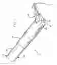
FIG. 1 is a partial break-away perspective view of a device in accordance with the present invention in a closed angled configuration;
FIG. 2 is a partial break-away perspective view of a device in accordance with the present invention in an open angled configuration; and
FIG. 3 is a cross-sectional perspective view of a device in accordance with the present invention in an opened straight configuration.
DETAILED DESCRIPTION OF THE INVENTION
Referring to the drawings more particularly by reference numbers, FIGS. 1, 2 and 3 show a preferred embodiment of the articulating actuating device 10. The device 10 includes a housing 12. The housing extends substantially the length of the instrument 10 and has a proximal end 14 and a distal end 16 and a longitudinal axis X. Disposed interiorly the housing 12 is an articulation rod 20 and an actuation rod 30. Each of the articulation rod 20 and the actuation rod 30 have respective proximal ends 22, 32 and distal ends 24, 34.
The proximal ends 22, 32 of the rods may be attached to a robotic system for the performance of minimally invasive surgical procedures. One such system is produced by Computer Motion, Inc. The assignee hereof and is described in U.S. Pat. No. 5,855,583, which is incorporated herein by reference.
The rods 20, 30 are attached to actuators via attachment means taught in U.S. Pat. No. 5,855,583. Other means for removably attaching a rod to an actuator are known in the art including the use of screws, clips or the like. In this way, each of the rods 20, 30 may be driven by the actuator which is connected to various user interfaces and power sources and are conducive to the performance of minimally invasive surgical procedures.
The articulation rod 20 extends substantially the length of the housing 12 along its longitudinal axis X. The articulation rod 20 is pivotally connected to a jaw 50. Such a pivotal connection may be accomplished through the use of a hinge 52 attached intermediate the articulation rod 20 and the jaw 50.
The jaw 50 pivotally communicates with the housing 12 at the distal end 16 thereof through the use of a rack 60. In this way, motion of the articulation rod 20 results in rotation of the jaw 50. The rack 60 provides a pivot about which the jaw 50 rotates.
The actuation rod 30 provides for actuation of the jaw 50. The actuation rod has a pin 36 disposed at the distal end 34 thereof. The pin 36 seats in a rack channel 72 disposed in a rack driver 70. The rack driver is pivotally attached to the housing 12 via a pin 74 or the like. The housing has two longitudinal apertures 18, 19 formed therethrough at the distal end 16 thereof to provide for lateral movement of the rack driver 70 which shall be described in detail hereinbelow.
Longitudinal motion of the actuation rod 30 moves the pin 36 in the rack channel 72 which translates the longitudinal motion of the actuation rod 30 into a pivotal motion of the rack driver 70. The rack driver 70 pivots about the pivot point defined by the pin 74 which attaches the rack driver 70 to the housing 12. The rack driver 70 may move outside of the space defined as the interior of the housing through the longitudinal apertures 18, 19.
The rack driver 70 has a shoulder 76 which engages the rack 60. As the rack driver 70 pivots, the shoulder 76 causes the rack 60 to move laterally, which is orthogonal to the longitudinal motion of the actuation rod 30 and orthogonal to the longitudinal axis of the housing 12. The rack 60 is slidably moveable within the housing 12 through two cylindrical apertures 13, 15 formed therethrough. As the rack 60 moves laterally, the jaw 50 is actuated. The lateral movement of the rack 60 is transferred to a first jaw element 54. A second jaw element 56 is pivotally connected to the first jaw element 54 via a pin 58 or the like and is held stationary with respect to the first jaw element 54. In this way, as the first jaw element is 54 is moved, the second jaw element 56 remains stationary and the jaw 50 is actuated. If each element has a sharp edge, then the jaw may function as a scissors.
The jaw 50 is always in communication with the rack 60, even as it is articulated through the motion of the articulation rod 20. This is accomplished through the use of a cylindrical rack having a circumferential channel 66 formed therein. The channel 66 receives the shoulder 76 of the rack driver 70 as well as a shoulder 58 on the first jaw element 54. As such, as the jaw 50 is articulated, the shoulder 58 on the first jaw element 54 rotates within the circumferential channel 66 in the rack 60 maintaining communication therein and providing for actuation of the jaw 50 regardless of the articulated position of the jaw 50 caused through motion of the articulation rod 20.
In this fashion, the articulation of the jaw 50 and the actuation of the jaw 50 are decoupled. It is highly advantageous to provide for a rigidly linked device that is decoupled in this fashion for several reasons. First, the device is easily steralizable and secondly, the device is quite safe to use as there is no use of tensioned cables or the like.
While certain exemplary embodiments have been described and shown in the accompanying drawings, it is to be understood that such embodiments are merely illustrative of and not restrictive on the broad invention, and that this invention not be limited to the specific constructions and arrangements shown and described, since various other modifications may occur to those ordinarily skilled in the art.
Claims
What is claimed is:1. A method for minimally invasive surgery comprising:
moving a first rod along a longitudinal axis of an elongate housing having a proximal end and a distal end, the movement of the first rod causing an end effector to pivot about a hinge, the end effector operably coupled to the distal end of the housing; and
moving a second rod along the longitudinal axis of the elongate housing, the movement of the second rod being translated into rotational movement of the end effector by a pin confined to an arcuate channel, the pin being orthogonal to the direction of movement caused by the second rod.
2. The method of claim 1, the end effector comprising a first gripper and a second gripper, the rotational movement of the end effector comprising rotation of the first gripper relative to the second gripper.
3. The method of claim 2, the arcuate channel for receiving the pin being disposed on the second rod.
4. The method of claim 2, the pin being disposed on the second rod.
5. The method of claim 4, the pin coupled to the distal end of the second rod, a translational member supporting the arcuate channel, the moving the second rod causing pivoting of the translational member about a housing pin connecting the translational member to the housing.
6. The method of claim 5, the translational member further comprising a shoulder engaged with a cylindrical rack to cause rotational movement of the first gripper when said second rod is longitudinally moved.
Images & Drawings included:


Sources:
- United States Patent and Trademark Office - verify current appl. status at the USPTO↗
Similar patent applications:
- » 20080103524
Rigidly-linked articulating wrist with decoupled motion transmission - » 20080312668
RIGIDLY-LINKED ARTICULATING WRIST WITH DECOUPLED MOTION TRANSMISSION - » 20110112571
RIGIDLY-LINKED ARTICULATING WRIST WITH DECOUPLED MOTION TRANSMISSION - » 20130030449
Rigidly-linked articulating wrist with decoupled motion transmission - » 20150018846
Rigidly-linked articulating wrist with decoupled motion transmission
Recent applications in this class:
- » 20250235088 2025-07-24
TOOL DRIVE ADAPTOR FOR ROBOTIC SURGICAL INSTRUMENT - » 20250204755 2025-06-26
Articulation member for or in a deflection mechanism - » 20250176804 2025-06-05
ENDOSCOPE HOLDING DEVICE, ENDOSCOPIC SURGERY SYSTEM, AND CONTROL METHOD - » 20250107697 2025-04-03
MANAGING AND MANIPULATING A LONG LENGTH ROBOTIC ENDOSCOPE - » 20250082184 2025-03-13
TECHNIQUES FOR CONTROLLING AN IMAGING DEVICE - » 20250017449 2025-01-16
MOUNTING ARM FOR A SURGICAL DEVICE - » 20240398212 2024-12-05
SURGICAL SCOPE ADAPTER FOR ACTUATED MANEUVERING OF SCOPES - » 20240389836 2024-11-28
METHOD FOR POSITIONING AN ENDOSCOPE WITH FLEXIBLE SHAFT - » 20240324856 2024-10-03
SURGICAL TROCAR WITH INTEGRATED CAMERAS - » 20240306895 2024-09-19
INSTRUMENT PARKING ASSISTANCE
Recent applications for this Assignee:
- » 20250290810 2025-09-18
SPLIT BRIDGE CIRCUIT FORCE SENSOR - » 20250288380 2025-09-18
TRANSMISSION ASSEMBLY FOR DRIVING INSTRUMENT INSERTION, AND RELATED DEVICES, SYSTEMS AND METHODS - » 20250288379 2025-09-18
TRANSMISSION ASSEMBLY FOR DRIVING INSTRUMENT INSERTION, AND RELATED DEVICES, SYSTEMS, AND METHODS - » 20250288368 2025-09-18
RADAR GRAPHICAL USER INTERFACE FOR ROBOTIC MEDICAL SYSTEMS - » 20250288349 2025-09-18
PERMEABILIZATION AND ELECTROLYSIS FOR ABLATION WITH EXTRACELLULAR MATRIX RETENTION - » 20250288291 2025-09-18
TRANSMISSION ASSEMBLY FOR DRIVING INSTRUMENT MOTION, AND RELATED DEVICES, SYSTEMS AND METHODS - » 20250282055 2025-09-11
RAIL ASSEMBLY FOR TABLE-MOUNTED MANIPULATOR SYSTEM, AND RELATED DEVICES, SYSTEMS AND METHODS - » 20250276444 2025-09-04
FORCE TRANSMISSION MECHANISMS AND RELATED DEVICES AND METHODS - » 20250275830 2025-09-04
MODULAR CLAMPS FOR MOUNTING SURGICAL MANIPULATORS - » 20250275829 2025-09-04
ARTICULATION MECHANISMS FOR INSTRUMENTS, AND RELATED DEVICES AND METHODS