Articulate continuous miner
US20100219675A1
2010-09-02
12/380,494
2009-03-02
✅ Patent granted
US 8,240,776 B2
2012-08-14
-
-
Sunil Singh
2029-09-07
Abstract:
A continuous mining machine in which the machine is capable of mining a width exceeding the width of the machine chassis by articulating the cutter end of the machine relative to the rear of the machine.
Interested in similar patents?
Get notified when new applications in this technology area are published.
Classification:
E21F13/06 » CPC main
Transport specially adapted to underground conditions at or adjacent to the working face Transport of mined material
E21C27/24 » CPC further
Machines which completely free the mineral from the seam; Mineral freed by means not involving slitting by milling means acting on the full working face, i.e. the rotary axis of the tool carrier being substantially parallel to the working face
E21C25/00 IPC
Cutting machines, i.e. for making slits approximately parallel or perpendicular to the seam
E21C25/00 IPC
Cutting, Slitting, Dislodging
Description
BACKGROUND
To mine desired width, most continuous miners must move entire chassis side to side to achieve desired mining width, since the cutter assembly and rear chassis are fixed (other than height adjustment).
To achieve full cutting width desired without repositioning entire chassis, an articulation movement of cutter assembly relative to rear chassis of machine is needed.
SUMMARY OF INVENTION
It is the object of this invention to provide the ability to mine full desired mining width without repositioning the entire machine chassis.
The cutter boom assembly, gathering conveyor assembly, and yoke articulate (left/right) providing an ability to mine desired width while rear of machine is stationary.
BRIEF DESCRIPTION OF DRAWINGS
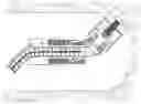
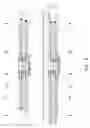
FIG. 1 General Arrangement of present invention
-
- Top and side view—straight ahead condition
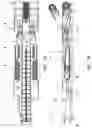
FIG. 2 General Arrangement of present invention
-
- Top and side view—swung condition
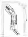
FIG. 3 General Arrangement of present invention
-
- Top and side view—swung condition
- Illustrated to show while mining
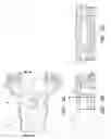
FIG. 4 General Arrangement of present invention
-
- Top and side view—alternate non-articulated version
FIG. 5 Articulation joint detail
FIG. 6 Section view taken at cutting plane 6-6 (See FIG. 5)
FIG. 7 Detail view of cutter head, gathering conveyor, and yoke
FIG. 8 Section view taken at cutting plane 8-8 (See FIG. 7)
FIG. 9 Section view taken at cutting plane 9-9 (See FIG. 7)
FIG. 10 Section view taken at cutting plane 10-10 (See FIG. 7)
FIG. 11 Section view taken at cutting plane 11-11 (See FIG. 7)
FIG. 12 Detail of cutter boom assembly
FIG. 13 Enlarged partial view of cutter boom assembly
FIG. 14 Schematic view of cutter drive assembly
FIG. 15 Detail of gathering conveyor assembly
FIG. 16 Schematic view of gathering conveyor assembly
FIG. 17 Detail of crawler assembly—top and side view
FIG. 18 Schematic view of crawler drive assembly
DETAILED DESCRIPTION OF DRAWINGS
FIGS. 1 & 2 General Arrangement of Present Invention
Cutter boom (1) and gathering conveyor (2) are connected to rear main frame (3) via yoke (4). Activation of swing cylinders (5) causes an articulation of front portion of the machine relative to rear portion of the machine. Propulsion of machine is facilitated by crawlers (6). Activation of boom swing cylinder (7) causes an articulation of discharge conveyor (8) to allow material to discharge at desired location.
FIG. 3 General Arrangement of Present Invention
With cutter rotating and conveyor running the machine sumps forward a predetermined distance then stops. After sumping, the machine swings left or right a predetermined distance then stops. The machine then swings in the opposite direction a predetermined distance then stops. The machine then returns to original position then re-sumps for the next cycle of operation.
FIG. 4 General Arrangement of Present Invention (Alternate Non-Articulated Version)
Cutter boom (1) and gathering conveyor (2) are connected to rear main frame (3). Propulsion of machine is facilitated by crawlers (6). Activation of boom swing cylinder (7) causes an articulation of discharge conveyor (8) to allow material to discharge at desired location.
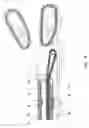
FIG. 5 Articulation Joint Detail
FIG. 6 Section View Taken at Cutting Plane 6-6 (See FIG. 5)
Yoke (4) and rear main frame (3) are connected via pins (9) and bearings (10). Thrust washers (11 & 12) are provided top and bottom—both connections.
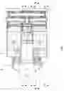
FIG. 7 Detail View of Cutter Head, Gathering Conveyor, and Yoke
FIG. 8 Section View Taken at Cutting Plane 8-8 (See FIG. 7)
Conveyor chain (13) passes thru yoke (4) from gathering conveyor (2) to discharge conveyor (8) top (carrying) side and lower (return) side.
FIG. 9 Section View Taken at Cutting Plane 9-9 (See FIG. 7)
Actuation of cutter lift cylinders (14) raises or lowers cutter boom (1)—pivoting at yoke (4).
FIG. 10 Section View Taken at Cutting Plane 10-10 (See FIG. 7)
Actuation of gathering head lift cylinders (15) raises or lowers gathering head (2) pivoting at the yoke (4).
FIG. 11 Section View Taken at Cutting Plane 11-11 (See FIG. 7)
FIG. 12 Detail of Cutter Boom Assembly
FIG. 13 Enlarged Partial View of Cutter Boom Assembly
FIG. 14 Schematic View of Cutter Drive Assembly
Electric motors (16) drive input gear (18) via torque shaft (17). Input gear (18) drives gear (19). Gear (19) is splined onto shaft/gear (20). Shaft/gear (20) drives gear (21). Gear (21) is splined onto shaft (22). Gear (23) is splined onto shaft (22). Shaft (22) and gear (23) drive idler gear (24). Idler gear (24) drives output gear (25). Output gear (25) is splined onto shaft (26). Ends of shaft (26) are splined onto hubs (27). Hubs (27) are rotatably fixed to drum (29) utilizing keys (28). The surface and ends of drum (29) are fitted with cutter bits (30) for mining material. The inboard ends of drum (29) are fitted with sprockets (31). Sprockets (31) engage with clearance cutting chain (32). Adjustable take-up roller (33) is provided to properly adjust tension of clearance cutting chain (32). Clearance cutting chain (32) is fitted with cutter bits (30) to cut clearance for gear housing (34).
FIG. 15 Detail of Gathering Conveyor Assembly
FIG. 16 Schematic View of Gathering Conveyor Assembly
Bevel pinion (35) is splined onto shaft of motor (36). Bevel pinion (35) drives bevel gear (37), Bevel gear (37) drives sun pinion (38). Sun pinion (38) drives planet gear (39). Planet gear (39) is engaged with stationary ring gear (40). Planet gear (39) rotates carrier (41) which is splined onto gear/shaft (42). Gear/shaft (42) drives idler gear (43). Idler gear (43) drives gear (44). Gear (44) and bevel gear (45) are fixed together. Bevel gear (45) drives bevel gear (46). Loading arms (47) rotate with bevel gear (46) to transfer mined material onto conveyor chain (13). Bevel gear (46) drives bevel gear (48). Bevel gear (48) is splined onto conveyor drive shaft (49). Conveyor drive shaft incorporates sprocket (50). Sprocket (50) engages with conveyor chain (13). Conveyor chain (13) propels mined material from receiving end of machine to discharge end of machine.
FIG. 17 Detail of Crawler Assembly—Top and Side View
FIG. 18 Schematic View of Crawler Drive Assembly
Pinion (52) is splined onto output shaft of motor (51). Pinion (52) drives gear (53). Gear (53) is splined onto gear/shaft (54). Gear shaft (54) drives gear (55). Gear (55) drives transfer shaft (56). Transfer shaft (56) is splined onto gear (57). Gear (57) drives idler gear (58). Idler gear (58) drives gear (59). Gear (59) is splined onto sun pinion/shaft (60). Sun pinion/shaft (60)drives planet gear (61). Planet gear (61) is engaged with stationary ring gear (62). Planet gear (61) rotates planet carrier (63). Planet carrier (63) is engaged with output sprockets (64). Output sprockets (64) are engaged with crawler chain (65) to propel machine. Adjustable roller (66) is provided to adjust tension of crawler chain (65).
Claims
What is claimed:1. An arrangement in which cutter boom (1) and gathering conveyor (2) articulate to provide a desired mining width via connection to yoke (4).
2. An arrangement in which cutter boom (1) can be raised or lowered independently while simultaneously able to articulate left or right via connection to yoke (4).
3. An arrangement in which gathering conveyor (2) can be raised or lowered independently while simultaneously able to articulate left or right via connection to yoke (4).
4. An arrangement in which cutter drive pinion gear/shaft (18) is driven by two independent motors (16).
Images & Drawings included:


Sources:
- United States Patent and Trademark Office - verify current appl. status at the USPTO↗
Recent applications in this class:
- » 20180010455 2018-01-11
Conveyor bridge - » 20170114639 2017-04-27
Controlling a conveyor in a mining system - » 20160356159 2016-12-08
Systems and methods for controlling a conveyor in a mining system - » 20160356158 2016-12-08
Conveyor bridge - » 20100276258 2010-11-04
Belt conveyors and mining - » 15629792 2018-07-31
Control system for material gathering mechanism