Weld assembly
US20100226731A1
2010-09-09
12/539,570
2009-08-11
✅ Patent granted
US 8,105,002 B2
2012-01-31
-
-
Flemming Saether
2030-06-09
Abstract:
A weld nut includes a main body and a flange. The flange is extended outwardly from the main body and surrounding the main body, and comprises teeth disposed evenly on the periphery thereof. Mis-positioning of the weld nut is avoided when soldering the weld nut to a printed circuit board.
Inventors:
- KUN-CHIH HSIEH 35 🇹🇼 Tu-Cheng, Taiwan
- JIAN-QIANG ZHAO 8 🇨🇳 Shenzhen City, China
- FAN-PENG ZENG 2 🇨🇳 Shenzhen City, China
- LIN-HE LI 1 🇨🇳 Shenzhen City, China
- Kun-Chih Hsieh 13 🇹🇼 Taipei Hsien, Taiwan
- Jian-Qiang Zhao 4 🇨🇳 Shenzhen, China
- Fan-Peng Zeng 1 🇨🇳 Shenzhen, China
- Lin-He Li 1 🇨🇳 Shenzhen, China
Assignee:
- HON HAI PRECISION INDUSTRY CO., LTD. 12,833 🇹🇼 Tu-Cheng, Taiwan
- HONG FU JIN PRECISION INDUSTRY (SHENZHEN) CO., LTD. 4,225 🇨🇳 Shenzhen City, China
- HON HAI PRECISION INDUSTRY CO., LTD. 2,724 🇹🇼 Tu-Cheng, New Taipei, Taiwan
- Hong Fu Jin Precision Industry (Shenzhen) Co., Ltd. 1,915 🇨🇳 Shenzhen, Guangdong Province, China
Interested in similar patents?
Get notified when new applications in this technology area are published.
Classification:
F16B37/061 » CPC main
Nuts or like thread-engaging members; Devices for fastening nuts to surfaces, e.g. sheets, plates by means of welding or riveting by means of welding
H05K3/341 » CPC further
Apparatus or processes for manufacturing printed circuits; Assembling printed circuits with electric components, e.g. with resistor electrically connecting electric components or wires to printed circuits by soldering Surface mounted components
H05K3/341 » CPC further
Apparatus or processes for manufacturing printed circuits; Assembling printed circuits with electric components, e.g. with resistor electrically connecting electric components or wires to printed circuits by soldering Surface mounted components
H05K1/182 » CPC further
Printed circuits; Printed circuits structurally associated with non-printed electric components associated with components mounted in the printed circuit board, e.g. insert mounted components [IMC]
H05K1/182 » CPC further
Printed circuits; Printed circuits structurally associated with non-printed electric components associated with components mounted in the printed circuit board, e.g. insert mounted components [IMC]
H05K2201/1031 » CPC further
Indexing scheme relating to printed circuits covered by; Details of components or other objects attached to or integrated in a printed circuit board; Other objects, e.g. metallic pieces Surface mounted metallic connector elements
H05K2201/1031 » CPC further
Indexing scheme relating to printed circuits covered by; Details of components or other objects attached to or integrated in a printed circuit board; Other objects, e.g. metallic pieces Surface mounted metallic connector elements
H05K2201/10409 » CPC further
Indexing scheme relating to printed circuits covered by; Details of components or other objects attached to or integrated in a printed circuit board; Other objects, e.g. metallic pieces Screws
H05K2201/10409 » CPC further
Indexing scheme relating to printed circuits covered by; Details of components or other objects attached to or integrated in a printed circuit board; Other objects, e.g. metallic pieces Screws
Y02P70/50 » CPC further
Climate change mitigation technologies in the production process for final industrial or consumer products Manufacturing or production processes characterised by the final manufactured product
Y02P70/50 » CPC further
Climate change mitigation technologies in the production process for final industrial or consumer products Manufacturing or production processes characterised by the final manufactured product
F16B37/06 IPC
Nuts or like thread-engaging members; Devices for fastening nuts to surfaces, e.g. sheets, plates by means of welding or riveting
Description
BACKGROUND
1. Technical Field
The present disclosure relates to a weld nut.
2. Description of Related Art
Weld nuts are used in electronic devices to connect components. The weld nut is soldered on a first component, such as a printed circuit board. A screw passes through a hole defined in a second component, and is screwed into the nut, thus connecting the two components.
Soldering is used to connect the nut to the first component. However, the solder used may be disposed unevenly, causing the nut to be mis-positioned and thus unsuitable.
What is needed is a weld nut which can be soldered accurately in position on a component.
BRIEF DESCRIPTION OF THE DRAWINGS
Many aspects of the embodiments can be better understood with reference to the following drawings. The components in the drawings are not necessarily drawn to scale, the emphasis instead being placed upon clearly illustrating the principles of the present disclosure. Moreover, in the drawings, like reference numerals designate corresponding parts throughout the several views.
FIG. 1 is a schematic, isometric view of a weld nut according to an exemplary embodiment.
FIG. 2 is a schematic, front view of the weld nut of FIG. 1.
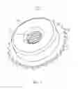
FIG. 3 is a schematic, top view showing the weld nut of FIG. 1 soldered on a printed circuit board.
FIG. 4 is a section view along A-A line of FIG. 3.
DETAILED DESCRIPTION
Referring to FIGS. 1 and 2, a weld nut 10 according to an exemplary embodiment is disclosed. The weld nut 10 includes a main body 20 and a flange 30 extended outwardly from the main body 20 and surrounding the main body 20. In this embodiment, the flange 30 is extended from a middle portion of the main body 20, thus dividing the main body 20 into a connection portion 22 and a plug portion 23. In other embodiments, the flange 30 may be extended from either end of the main body 20.
The main body 20 defines an axial threaded hole 21 therein.[0012] The flange 30 is gear shaped and teeth 31 of the flange are disposed evenly on the periphery of the flange 30.
Referring to FIGS. 3 and 4, a printed circuit board (PCB) 50 defines a mounting hole 51. The mounting hole 51 is bigger than the plug portion 23 of the weld nut 10, and is smaller than the flange 30 in diameter. The mounting hole 51 is equal to or bigger than the plug portion 23 in height.
In assembly, firstly solder 60 is applied on the PCB 50 around the mounting hole 51. The plug portion 23 of the weld nut 10 is inserted into the mounting hole 51 till the flange 30 contacts the solder 60. The solder 60 is soldered and melted. Portion of the solder 60 is disposed evenly below the flange 30, and connects the weld nut 10 to the PCB 50. The remaining solder 60 flows into gaps between the teeth 31 of the flange 30, and adheres to the teeth 31. Because the remaining solder 60 flows into the gaps and does not collect under the flange 30, mis-positioning of the weld nut 10 is avoided. And, as the solder 60 in the gaps adheres to the evenly disposed teeth 31, the weld nut 10 is soldered to the PCB 50 firmly and evenly.
Moreover, it is to be understood that the disclosure may be embodied in other forms without departing from the spirit thereof. Thus, the present examples and embodiments are to be considered in all respects as illustrative and not restrictive, and the disclosure is not to be limited to the details given herein.
Claims
What is claimed is:1. A weld nut comprising:
a main body; and
a flange extended outwardly from the main body and surrounding the main body, wherein the flange comprises teeth disposed evenly on a periphery thereof.
2. The weld nut of claim 1, wherein the flange is extended outwardly from a middle portion of the main body.
3. The weld nut of claim 1, wherein the flange is extended outwardly from an end of the main body.
4. The weld nut of claim 1, wherein the main body defines an axial threaded hole therein.
5. The weld nut of claim 1, wherein the flange is gear shaped.
Images & Drawings included:


Sources:
- United States Patent and Trademark Office - verify current appl. status at the USPTO↗
Similar patent applications:
- » 20210178519
METHOD FOR PRODUCING A WELDING ASSEMBLY, AND WELDING ASSEMBLY - » 20190118285
WELDING CABLE ASSEMBLIES, WELDING TORCH ASSEMBLIES, AND ROBOTIC WELDING SYSTEMS - » 20180306302
Method for forming a welded assembly and related welded assembly - » 20180306300
METHOD FOR FORMING A WELDED ASSEMBLY AND RELATED WELDED ASSEMBLY - » 20150086262
Welded assemblies and methods of making welded assemblies - » 20180290238
Welded assemblies and methods of making welded assemblies - » 20180311903
Welding assembly and method for producing a welding assembly - » 10622888
Friction stir welded assembly and method of forming a friction stir welded assembly - » 20200316727
WELDING ASSEMBLY, WELDING PLANT AND METHOD FOR WELDING - » 20190054561
Welding assembly for welding two rails of a track
Recent applications in this class:
- » 20250102009 2025-03-27
PROJECTION WELDED JOINT AND PROJECTION WELDING METHOD - » 20230296125 2023-09-21
Member for fastening and method of manufacturing same - » 20230091592 2023-03-23
DISSIMILAR MATERIAL JOINT STRUCTURE AND METHOD FOR JOINING DISSIMILAR MATERIALS - » 20200392976 2020-12-17
Partially-threaded projection weld nut - » 20200217351 2020-07-09
WELDABLE CLINCH NUT - » 20200063781 2020-02-27
Weldable nut plate - » 20190055979 2019-02-21
WELD STUDS FOR USE IN FLUID CONTROL BODIES - » 20170074313 2017-03-16
Stand-off weld stud - » 20170058936 2017-03-02
WELD NUT - » 20160040706 2016-02-11
Arc weld stud having a forming thread
Recent applications for this Assignee:
- » 20140233961 2014-08-21
Optical communication module including optical-electrical signal converters and optical signal generators - » 20140083669 2014-03-27
HEAT SINK - » 20140083669 2014-03-27
HEAT SINK - » 20140063746 2014-03-06
Electronic device with heat dissipation assembly - » 20140061224 2014-03-06
AUTOMATIC VENDING MACHINE - » 20140060914 2014-03-06
Enclosure with shield apparatus - » 20140058727 2014-02-27
MULTIMEDIA RECORDING SYSTEM AND METHOD - » 20140055955 2014-02-27
Fastener - » 20140055322 2014-02-27
DISPLAY SYSTEM AND HEAD-MOUNTED DISPLAY APPARATUS - » 20140054439 2014-02-27
CONTAINER DATA CENTER WITH SUPPORTING APPARATUS