INTELLIGENT DIGITAL PHOTO FRAME
US20100265227A1
2010-10-21
12/485,049
2009-06-16
Abstract:
A digital photo frame (DPF) includes a power management unit connected to a power source, configured for distributing power from the power source to the DPF; a display panel configured for displaying displayable media; a motion sensor configured for detecting whether there is someone around the DPF and producing a trigger signal when having detected that someone is around the DPF; a light detector configured for detecting current ambient light level and producing a light signal corresponding to the detected ambient light level; and a processing unit configured for adjusting brightness of the display panel according to the trigger signal and the light signal.
Inventors:
- KUAN-HONG HSIEH 196 🇹🇼 Tu-Cheng, Taiwan
- XIAO-GUANG LI 145 🇨🇳 Shenzhen City, China
- MING-FENG TSAI 25 🇹🇼 Tu-Cheng, Taiwan
- CHUNG-JEN LAN 9 🇹🇼 Tu-Cheng, Taiwan
Assignee:
- HON HAI PRECISION INDUSTRY CO., LTD. 12,828 🇹🇼 Tu-Cheng, Taiwan
- HONG FU JIN PRECISION INDUSTRY (SHENZHEN) CO., LTD. 4,225 🇨🇳 Shenzhen City, China
Interested in similar patents?
Get notified when new applications in this technology area are published.
Classification:
G09G3/20 » CPC main
Control arrangements or circuits, of interest only in connection with visual indicators other than cathode-ray tubes for presentation of an assembly of a number of characters, e.g. a page, by composing the assembly by combination of individual elements arranged in a matrix no fixed position being assigned to or needed to be assigned to the individual characters or partial characters
H04N1/00347 » CPC further
Scanning, transmission or reproduction of documents or the like, e.g. facsimile transmission; Details thereof; Connection or combination of a still picture apparatus with another apparatus, e.g. for storage, processing or transmission of still picture signals or of information associated with a still picture with another still picture apparatus, e.g. hybrid still picture apparatus
H04N1/0044 » CPC further
Scanning, transmission or reproduction of documents or the like, e.g. facsimile transmission; Details thereof; User-machine interface; Control console; Output means; Display of information to the user, e.g. menus for image preview or review, e.g. to help the user position a sheet
H04N1/00896 » CPC further
Scanning, transmission or reproduction of documents or the like, e.g. facsimile transmission; Details thereof; Power supply means, e.g. arrangements for the control of power supply to the apparatus or components thereof; Control thereof using a low-power mode, e.g. standby
G09G2320/0626 » CPC further
Control of display operating conditions; Adjustment of display parameters for control of overall brightness
G09G2330/022 » CPC further
Aspects of power supply; Aspects of display protection and defect management; Details of power systems and of start or stop of display operation; Power management, e.g. power saving in absence of operation, e.g. no data being entered during a predetermined time
G09G2330/023 » CPC further
Aspects of power supply; Aspects of display protection and defect management; Details of power systems and of start or stop of display operation; Power management, e.g. power saving using energy recovery or conservation
G09G5/00 IPC
Control arrangements or circuits for visual indicators common to cathode-ray tube indicators and other visual indicators
H04N5/66 IPC
Details of television systems Transforming electric information into light information
H04N5/57 IPC
Details of television systems; Receiver circuitry for the reception of television signals according to analogue transmission standards Control of contrast or brightness
Description
RELATER APPLICATIONS
This application is related to copending applications entitled, “INTELLIGENT DIGITAL PHOTO FRAME”, filed ______ (Atty. Docket No. US 24557); “INTELLIGENT DIGITAL PHOTO FRAME”, filed ______ (Atty. Docket No. US24558); “INTELLIGENT DIGITAL PHOTO FRAME”, filed ______ (Atty. Docket No. US24561); and “INTELLIGENT DIGITAL PHOTO FRAME”, filed ______ (Atty. Docket No. US24562).
BACKGROUND
1. Technical Field
The disclosure relates to electronic devices and, particularly, to a digital photo frame.
2. Description of Related Art
Nowadays, digital photos are getting more and more popular while digital cameras are becoming more and more affordable. Accordingly, in order to conveniently display digital photos, digital photo frames are invented. Unfortunately, manual adjustment of settings of the digital photo frames is required when adjustments are desired.
Therefore, it is useful to provide a digital photo frame capable of adjusting brightness automatically.
BRIEF DESCRIPTION OF THE DRAWINGS
The components in the drawing are not necessarily drawn to scale, the emphasis instead being placed upon clearly illustrating the principles of the digital photo frame.
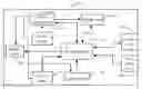
The drawing is a block diagram of a digital photo frame in accordance with an exemplary embodiment.
DETAILED DESCRIPTION
Referring to the drawing, a digital photo frame (DPF) 1 includes a processing unit 10, a power source 20, a light detector 30, a motion sensor 40, a power management unit 50, a display panel 60, a storage unit 70, a user input unit 80, and an interface unit 90 (e.g., an input port or wireless transceiver). The DPF 1 is capable of adjusting brightness automatically upon sensing someone around the DPF 1 within a predetermined area and the ambient light level being relatively dark.
The storage unit 70 is configured to store displayable media such as digital pictures. The display panel 60 is configured to display the displayable media stored in the storage unit 70. The user input unit 80 is configured to generate instructions in response to user operations. The user input unit 80 can be input keys/buttons, knobs, and the like. The interface unit 90 is configured to connect to an external electronic device (not shown). The external device can be a storage card (e.g., a secure digital SD card, a compact flash CF card) or another electronic device (e.g., a digital camera, a mobile phone, or a computer).
The storage unit 70 is further configured to store a table. The table includes a plurality of light level ranges and a plurality of preferred brightness values corresponding to the light level ranges relatively. The light level ranges represent various ranges of ambient light levels, for example, the ambient light level is quite dark, dark, normal, bright, quite bright and so on. For each light level range, there is one preferred brightness value accordingly. The table maybe pre-stored in the memory 70, or set by the user through the user input unit 80.
The power source 20 can be a battery or an AC/DC (alternating current to direct current) module. The power management unit 50 is configured to distribute power from the power source 20 to elements of the DPF 1, such as the processing unit 10, the motion sensor 40, the light detector 30, and the display panel 60.
The light detector 30 is configured to detect a current ambient light level and produce a light signal to the processing unit 10.
The motion sensor 40, connected to the processing unit 10, is configured for detecting whether there is someone around the DPF 1 within a predetermined area, and producing a trigger signal to the processing unit 10 when there is. The motion sensor 40 may include any one or more of the following, an infrared detector, a sonar detector, an audio detector, or the like, which can work singly or in combination according to preset parameters to generate a signal when it is likely one or more persons are present in the predetermined area.
The processing unit 10 is configured to control the power management unit 50 to power on the light detector 30 when receiving the trigger signal. The processing unit 10 is also configured to convert the light signal to digital light level value, look up the digital light level value in the table in the storage unit 70 to determine the light level range that the digital light level value is included in, obtain the preferred brightness value according to the determined light level range, and adjust the brightness of the display panel 60.
In the embodiment, the motion sensor 40 continuously detects whether there is someone around the DPF 1. The motion sensor 40 is also configured to produce a stop signal when it detects that nobody is within the predetermined area and when a predetermined time period has elapsed after the display panel 60 was powered on. The processing unit 10 controls the power management unit 50 to discontinue the power to the display panel 60 and other elements of the DPF 1 whose functions are not currently needed when receiving the stop signal. Thereby, if there is nobody around the DPF 1, the DPF 1 will be powered off automatically to avoid wasting power. The predetermined time period may be pre-stored in the storage unit 70, or be preset by the user through the user input unit 80.
In another embodiment, the preferred brightness value can instead be a preferred brightness range. When the brightness range is obtained after the light level range is determined, the processing unit can change the brightness of the display panel 60 according to any value within the preferred brightness range.
It is believed that the present embodiments and their advantages will be understood from the foregoing description, and it will be apparent that various changes may be made thereto without departing from the spirit and scope of the disclosure or sacrificing all of its material advantages, the examples hereinbefore described merely being preferred or exemplary embodiments of the present disclosure.
Claims
What is claimed is:1. A digital photo frame (DPF) for automatically adjusting brightness, comprising:
a power management unit connected to a power source, configured for distributing power from the power source to the DPF;
a display panel configured for displaying displayable media;
a motion sensor configured for detecting whether there is someone around the DPF and producing a trigger signal when having detected that someone is around the DPF;
a light detector configured for detecting current ambient light level and producing a light signal corresponding to the detected ambient light level; and
a processing unit configured for adjusting brightness of the display panel according to the trigger signal and the light signal.
2. The DPF of claim 1, wherein the processing unit is configured to control the light detector to work when receiving the trigger signal.
3. The DPF of claim 1, further comprising a storage unit configured for storing a plurality of light level ranges and a plurality of preferred brightness values corresponding to the light level ranges, wherein the processing unit is further configured to convert the light signal to a digital light level value, compare the digital light level value with the light level ranges to determine one light level range that the digital light level value is included in, obtain the preferred brightness value according to the determined light level range, and adjust the brightness of the display panel according to the preferred brightness value.
4. The DPF of claim 1, comprising a storage unit configured for storing a plurality of light level ranges and a plurality of preferred brightness ranges corresponding to the light level ranges, wherein the processing unit is further configured to convert the light signal to a digital light level value, compare the digital light level value with the light level ranges to determine one light level range that the digital light level value is included in, obtain the preferred brightness range according to the determined light level range, and adjust the brightness of the display panel according to one value within the preferred brightness range.
5. The DPF of claim 1, wherein the motion sensor comprises one selected from the group consisting of an infrared detector, a sonar detector, and an audio detector.
6. The DPF of claim 1, wherein the motion sensor comprises two or more of the infrared detector, the sonar detector, or the audio detector.
7. The DPF of claim 1,wherein the motion sensor is further configured to produce a stop signal when it detects that nobody is within the predetermined area and when a predetermined time period has elapsed after the display panel was powered on, and the processing unit is further configured to control the power management unit to discontinue the power to the display panel and other elements of the DPF whose functions are not currently needed when receiving the stop signal.
8. A method of automatically adjusting brightness of a digital photo frame (DPF), the method comprising:
detecting whether there is someone around the DPF and producing a trigger signal when having detected that someone is around the DPF;
detecting current ambient light level and producing a light signal corresponding to the detected ambient light level; and
adjusting brightness of a display panel of the DPF according to the trigger signal and the light signal.
9. The method of claim 8, wherein the step of detecting current ambient light level and producing a light signal further comprises:
controlling a light detector of the DPF to work when receiving the trigger signal.
10. The method of claim 8, further comprising:
supplying a storage unit for storing media for displaying, a plurality of light level ranges and a plurality of preferred brightness values corresponding to the light level ranges;
converting the light signal to a digital light level value;
comparing the digital light level value with the light level ranges to determine one light level range that the digital light level value is included in;
obtaining the preferred brightness value according to the determined light level range; and
adjusting the brightness of the display panel according to the preferred brightness value.
11. The method of claim 8, further comprising:
supplying a storage unit for storing media for displaying, a plurality of light level ranges and a plurality of preferred brightness ranges corresponding to the light level ranges;
converting the light signal to a digital light level value;
comparing the digital light level value with the light level ranges to determine one light level range that the digital light level value is included in;
obtaining the preferred brightness range according to the determined light level range; and
adjusting the brightness of the display panel according to one value within the preferred brightness range.
12. The method of claim 8, further comprising:
producing a stop signal when detecting that nobody is within the predetermined area and when a predetermined time period has elapsed after the display panel was powered on; and
controlling the power management unit to discontinue the power to the display panel and other elements of the DPF whose functions are not currently needed when receiving the stop signal.
Images & Drawings included:

Sources:
- United States Patent and Trademark Office - verify current appl. status at the USPTO↗
Similar patent applications:
- » 20100013810
Intelligent digital photo frame - » 20100271355
INTELLIGENT DIGITAL PHOTO FRAME - » 20100271384
INTELLIGENT DIGITAL PHOTO FRAME - » 20100271385
INTELLIGENT DIGITAL PHOTO FRAME - » 20100271552
INTELLIGENT DIGITAL PHOTO FRAME
Recent applications in this class:
- » 20250174166 2025-05-29
DISPLAY DEVICE - » 20250166542 2025-05-22
SHIFT REGISTER AND DRIVING METHOD THEREFOR, GATE DRIVING CIRCUIT, AND DISPLAY DEVICE - » 20250166541 2025-05-22
GATE DRIVING CIRCUIT AND DRIVING METHOD THEREOF, AND DISPLAY DEVICE - » 20250157377 2025-05-15
AMBIENT LIGHT AND PROXIMITY DETECTION METHOD, PHOTOGRAPHING METHOD, AND TERMINAL - » 20250157376 2025-05-15
DISPLAY APPARATUS AND METHOD OF OPERATING THE SAME - » 20250157375 2025-05-15
EMISSION DRIVER, GATE DRIVER, AND DISPLAY DEVICE - » 20250148951 2025-05-08
DRIVER CIRCUIT DRIVING DISPLAY PANEL IN TWO MODES - » 20250148950 2025-05-08
DISPLAY PANEL, DISPLAY DEVICE AND DRIVING METHOD - » 20250140149 2025-05-01
ARRAY SUBSTRATE AND DISPLAY DEVICE - » 20250140148 2025-05-01
DISPLAY DEVICE AND IMAGE DISPLAY METHOD THEREOF
Recent applications for this Assignee:
- » 20140233961 2014-08-21
Optical communication module including optical-electrical signal converters and optical signal generators - » 20140083669 2014-03-27
HEAT SINK - » 20140083669 2014-03-27
HEAT SINK - » 20140063746 2014-03-06
Electronic device with heat dissipation assembly - » 20140061224 2014-03-06
AUTOMATIC VENDING MACHINE - » 20140060914 2014-03-06
Enclosure with shield apparatus - » 20140058727 2014-02-27
MULTIMEDIA RECORDING SYSTEM AND METHOD - » 20140055955 2014-02-27
Fastener - » 20140055322 2014-02-27
DISPLAY SYSTEM AND HEAD-MOUNTED DISPLAY APPARATUS - » 20140054439 2014-02-27
CONTAINER DATA CENTER WITH SUPPORTING APPARATUS