Starting circuit for single-phase AC motor
US20100270966A1
2010-10-28
12/726,507
2010-03-18
✅ Patent granted
US 8,248,020 B2
2012-08-21
-
-
Karen Masih
2031-03-03
Abstract:
A starting circuit for a single-phase AC motor, consisting at least of a rectifying and voltage-stabilizing circuit, a control circuit with a zero-cross detecting circuit and a counter, and a bidirectional thyristor. The bidirectional thyristor is serially connected to a starting winding and a starting capacitor, the bidirectional thyristor, the starting winding and the starting capacitor are connected a utility power AC input. The input end of the rectifying and voltage-stabilizing circuit is connected to the utility power AC input. The output end of the rectifying and voltage-stabilizing circuit supplies power to the control circuit. The input end of the zero-cross detecting circuit is connected to the utility power AC input. The output end of the zero-cross detecting circuit is connected to the input end of the counter. The zero-cross detecting circuit detects zero crossing points of the utility power AC input and inputs the zero crossing points to the counter.
Assignee:
- ZHONGSHAN BROAD-OCEAN MOTOR CO., LTD. 165 🇨🇳 Zhongshan, China
Interested in similar patents?
Get notified when new applications in this technology area are published.
Classification:
H02P1/44 » CPC main
Arrangements for starting electric motors or dynamo-electric converters for starting dynamo-electric motors or dynamo-electric converters for starting an individual single-phase induction motor by phase-splitting with a capacitor
H02P1/16 IPC
Arrangements for starting electric motors or dynamo-electric converters for starting dynamo-electric motors or dynamo-electric converters
H02P1/26 IPC
Arrangements for starting electric motors or dynamo-electric converters for starting dynamo-electric motors or dynamo-electric converters for starting an individual polyphase induction motor
Description
CROSS-REFERENCE TO RELATED APPLICATIONS
Pursuant to 35 U.S.C. §119 and the Paris Convention Treaty, this application claims the benefit of Chinese Patent Application No. 200920055886.4 filed on Apr. 27, 2009, the contents of which are incorporated herein by reference.
BACKGROUND OF THE INVENTION
1. Field of the Invention
The invention relates to a starting circuit, and more particularly to a starting circuit for a single-phase AC motor.
2. Description of the Related Art
Single-phase AC motors are widely used nowadays. A conventional starting circuit of the single-phase AC motor comprises a current-measuring circuit, a rectifying circuit, a comparing circuit, and a bidirectional thyristor. However, there are several problems with the starting circuit: control thereof is difficult, circuit structure thereof is complex, and production cost thereof is high.
SUMMARY OF THE INVENTION
In view of the above-described problem, it is one objective of the invention to provide a starting circuit for a single-phase AC motor that features easy control, simple structure, and low production cost.
To achieve the above objectives, in accordance with one embodiment of the invention, provided is a starting circuit for a single-phase AC motor, comprising a rectifying and voltage-stabilizing circuit, a control circuit comprising a zero-cross detecting circuit and a counter, and a bidirectional thyristor. The bidirectional thyristor is serially connected to a starting winding and a starting capacitor, the bidirectional thyristor, the starting winding and the starting capacitor are connected a utility power AC input, an input end of the rectifying and voltage-stabilizing circuit is connected to the utility power AC input, an output end of the rectifying and voltage-stabilizing circuit operates to supply power to the control circuit, an input end of the zero-cross detecting circuit is connected to the utility power AC input, an output end of the zero-cross detecting circuit is connected to an input end of the counter, the zero-cross detecting circuit operates to detect zero crossing points of the utility power AC input, and to input the zero crossing points to the counter, and the counter operates to trigger a signal whereby controlling the bidirectional thyristor as the total number of the zero crossing points reaches a predetermined value.
In a class of this embodiment, the zero-cross detecting circuit comprises a first resistor R1, a second resistor R2, a third resistor R3, a triode Q1.
In a class of this embodiment, the first resistor R1 and the second resistor R2 are serially connected altogether and then to the utility power AC input.
In a class of this embodiment, a base electrode of the triode Q1 is connected between the first resistor R1 and the second resistor R2.
In a class of this embodiment, the third resistor R3 is connected to one end of a power supply.
In a class of this embodiment, an emitting electrode of the triode Q1 is connected to the other end of the power supply.
In a class of this embodiment, a photoelectric-isolating and driving circuit is disposed between the counter and the bidirectional thyristor.
In a class of this embodiment, a protecting circuit is parallel connected to the bidirectional thyristor.
In a class of this embodiment, the protecting circuit comprises a capacitor C4 and a fourth resistor R1 serially connected altogether.
In a class of this embodiment, the predetermined value is adjustable.
Advantages of the invention comprise: 1) the invention features simple circuit structure, small components and low production cost; 2) the invention features easy control, during starting of the motor, a main winding and the starting winding operate simultaneously, the bidirectional thyristor is switched on, and the counter outputs a high-level signal to the control end of the bidirectional thyristor; meanwhile, the zero-cross detecting circuit inputs the zero crossing points to the counter, the counter triggers a low-level signal whereby controlling the bidirectional thyristor to switch off and enabling the starting winding to stop operating as the total number of the zero crossing points reaches a predetermined value; 3) the invention is safe and reliable, the photoelectric-isolating and driving circuit disposed between the counter and the bidirectional thyristor separates a heavy-current portion from a weak-current portion; 4) the invention features convenient use, the predetermined value of the counter is adjustable, and thus turn-on time of the bidirectional thyristor and operation time of the starting winding are controllable.
BRIEF DESCRIPTION OF THE DRAWINGS
Detailed description will be given below in conjunction with accompanying drawings, in which:
FIG. 1 is a block diagram of a starting circuit for a single-phase AC motor of an embodiment of the invention;
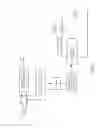
FIG. 2 is a schematic diagram of the starting circuit in FIG. 1; and
FIG. 3 is a waveform graph of a utility power AC input.
DETAILED DESCRIPTION OF THE EMBODIMENTS
As shown in FIGS. 1 and 2, a starting circuit for a single-phase AC motor of the invention comprises a rectifying and voltage-stabilizing circuit 1, a control circuit, and a bidirectional thyristor 5.
The bidirectional thyristor 5 is serially connected to a starting winding and a starting capacitor, the bidirectional thyristor 5, the starting winding and the starting capacitor are connected a utility power AC input.
An input end of the rectifying and voltage-stabilizing circuit 1 is connected to the utility power AC input, and an output end of the rectifying and voltage-stabilizing circuit 1 operates to supply power to the control circuit.
The control circuit comprises a zero-cross detecting circuit 2 and a counter 3.
The zero-cross detecting circuit 2 comprises a first resistor R1, a second resistor R2, a third resistor R3, a triode Q1. The first resistor R1 and the second resistor R2 are serially connected altogether and then to the utility power AC input. A base electrode of the triode Q1 is connected between the first resistor R1 and the second resistor R2. The third resistor R3 is connected to one end of a power supply, and an emitting electrode of the triode Q1 is connected to the other end of the power supply.
An input end of the zero-cross detecting circuit 2 is connected to the utility power AC input, and an output end of the zero-cross detecting circuit 2 is connected to an input end of the counter 3.
The zero-cross detecting circuit 2 operates to detect zero crossing points of the utility power AC input, and to input the zero crossing points to the counter 3.
The counter 3 operates to trigger a signal whereby controlling the bidirectional thyristor 5 as the total number of the zero crossing points reaches a predetermined value. The predetermined value is adjustable.
A photoelectric-isolating and driving circuit 4 is disposed between the counter 3 and the bidirectional thyristor 5.
A protecting circuit is parallel connected to the bidirectional thyristor 5, and comprises a capacitor C4 and a fourth resistor R1 serially connected altogether.
Operation principle of the invention is as follows:
As the single-phase AC motor is powered on and started, the bidirectional thyristor 5 is switched on, and the zero-cross detecting circuit 2 inputs zero crossing points of the utility power AC input to the counter 3. As shown in FIG. 3, the utility power AC input is a sine wave signal with a frequency of 50 Hz and a wave period of 0.02 s. The number and time of a waveform can be determined by detecting zero crossing points A1 and A2. The zero-cross detecting circuit 2 inputs zero crossing points of the utility power AC input to the counter 3. The counter 3 triggers a signal whereby controlling the bidirectional thyristor 5 to switch off and enabling the starting winding to stop operating as the total number of the zero crossing points reaches a predetermined value. The predetermined value is adjustable, which makes the invention applicable for single-phase AC motors with different parameters.
While particular embodiments of the invention have been shown and described, it will be obvious to those skilled in the art that changes and modifications may be made without departing from the invention in its broader aspects, and therefore, the aim in the appended claims is to cover all such changes and modifications as fall within the true spirit and scope of the invention.
Claims
The invention claimed is:1. A starting circuit for a single-phase AC motor, comprising
a rectifying and voltage-stabilizing circuit;
a control circuit comprising a zero-cross detecting circuit and a counter; and
a bidirectional thyristor;
wherein
said bidirectional thyristor is serially connected to a starting winding and a starting capacitor;
said bidirectional thyristor, said starting winding and said starting capacitor are connected a utility power AC input;
an input end of said rectifying and voltage-stabilizing circuit is connected to said utility power AC input;
an output end of said rectifying and voltage-stabilizing circuit operates to supply power to said control circuit;
an input end of said zero-cross detecting circuit is connected to said utility power AC input;
an output end of said zero-cross detecting circuit is connected to an input end of said counter;
said zero-cross detecting circuit operates to detect zero crossing points of said utility power AC input, and to input said zero crossing points to said counter; and
said counter operates to trigger a signal whereby controlling said bidirectional thyristor as the total number of said zero crossing points reaches a predetermined value.
2. The starting circuit of claim 1, wherein said zero-cross detecting circuit comprises a first resistor R1, a second resistor R2, a third resistor R3, a triode Q1.
3. The starting circuit of claim 2, wherein said first resistor R1 and said second resistor R2 are serially connected altogether and then to said utility power AC input.
4. The starting circuit of claim 2, wherein a base electrode of said triode Q1 is connected between said first resistor R1 and said second resistor R2.
5. The starting circuit of claim 2, wherein said third resistor R3 is connected to one end of a power supply.
6. The starting circuit of claim 5, wherein an emitting electrode of said triode Q1 is connected to the other end of said power supply.
7. The starting circuit of claim 1, wherein a photoelectric-isolating and driving circuit is disposed between said counter and said bidirectional thyristor.
8. The starting circuit of claim 1, wherein a protecting circuit is parallel connected to said bidirectional thyristor.
9. The starting circuit of claim 8, wherein said protecting circuit comprises a capacitor C4 and a fourth resistor R1 serially connected altogether.
10. The starting circuit of claim 1, wherein said predetermined value is adjustable.
Images & Drawings included:


Sources:
- United States Patent and Trademark Office - verify current appl. status at the USPTO↗
Similar patent applications:
Recent applications in this class:
- » 20240204698 2024-06-20
Controller and drive circuits for electric motors - » 20200177110 2020-06-04
Solar hybrid solution for single phase starting capacitor motor applications with grid start - » 20200044583 2020-02-06
Drive circuit for electric motors - » 20190165700 2019-05-30
Electronically controlled switch for an electric motor - » 20140132199 2014-05-15
Method for starting a single-phase induction motor, starting device for a single-phase motor and starting system therefor - » 20120274262 2012-11-01
VOLTAGE AND SPEED SENSITIVE MOTOR CONTROL STARTING CIRCUIT - » 20110193511 2011-08-11
Control circuit for single-phase AC motor of dryer - » 20110025254 2011-02-03
Single phase induction motor - » 20110001450 2011-01-06
Motor start circuit for an induction motor - » 20100207569 2010-08-19
Starting circuit for single-phase AC motor and method for starting single-phase AC motor
Recent applications for this Assignee:
- » 20240178777 2024-05-30
Method for pre-positioning rotor of outdoor fan in high-speed counter-rotation state before operation - » 20240063742 2024-02-22
MOTOR CONTROLLER AND BLDC MOTOR COMPRISING THE SAME - » 20240056009 2024-02-15
METHOD FOR CONTROLLING OPERATION OF PERMANENT-MAGNET SYNCHRONOUS MOTOR THROUGH SENSORLESS VECTOR CONTROL - » 20230412111 2023-12-21
Method for protecting motor from overheating - » 20230327585 2023-10-12
Method for coconstant torque control of EC motor in ventilation system - » 20230043468 2023-02-09
Method for controlling fuel cell - » 20230030515 2023-02-02
DC brushless motor controller comprising lightning protection and surge protection circuit - » 20220416629 2022-12-29
Motor controller and outer rotor motor comprising the same - » 20220307507 2022-09-29
Direct current induced draft fan - » 20220213901 2022-07-07
Air blower and exhaust fan comprising the same