LCD and display property adjusting method thereof
US20100302222A1
2010-12-02
12/497,710
2009-07-06
✅ Patent granted
US 8,243,054 B2
2012-08-14
-
-
Amare Mengistu | Koosha Sharifi-Tafreshi
2031-01-15
Abstract:
A liquid crystal display (LCD) includes a graphic processor, a number of sensors, an optical signal collecting unit, a property saving unit, a property comparing unit, and a property setting unit. The optical signal collecting unit receives optical analog signals generated by the number of sensors, and converts the received optical analog signals into optical digital signals. The property saving unit saves a number of predetermined display properties and a number of predetermined optical signal ranges. The property comparing unit receives the optical digital signals and compares the optical digital signals with the plurality of predetermined optical signal ranges, and correspondingly selects corresponding predetermined display properties. The property setting unit receives the selected display properties and outputs the selected display properties to the graphic processor to adjust display properties of the LCD.
Inventors:
- Ming-Chih HSIEH 130 🇹🇼 Tu-Cheng, Taiwan
- YANG-YUAN CHEN 22 🇹🇼 Tu-Cheng, Taiwan
- MING-CHIH HSIEH 63 🇹🇼 Taipei Hsien, Taiwan
- Yang-Yuan Chen 14 🇹🇼 Taipei Hsien, Taiwan
Assignee:
- HON HAI PRECISION INDUSTRY CO., LTD. 12,833 🇹🇼 Tu-Cheng, Taiwan
- HON HAI PRECISION INDUSTRY CO., LTD. 2,724 🇹🇼 Tu-Cheng, New Taipei, Taiwan
Interested in similar patents?
Get notified when new applications in this technology area are published.
Classification:
G01J1/10 » CPC main
Photometry, e.g. photographic exposure meter by comparison with reference light or electric value provisionally void
G09G3/3611 » CPC further
Control arrangements or circuits, of interest only in connection with visual indicators other than cathode-ray tubes for presentation of an assembly of a number of characters, e.g. a page, by composing the assembly by combination of individual elements arranged in a matrix no fixed position being assigned to or needed to be assigned to the individual characters or partial characters by control of light from an independent source using liquid crystals Control of matrices with row and column drivers
G09G2320/0626 » CPC further
Control of display operating conditions; Adjustment of display parameters for control of overall brightness
G09G2320/066 » CPC further
Control of display operating conditions; Adjustment of display parameters for control of contrast
G09G2320/0666 » CPC further
Control of display operating conditions; Adjustment of display parameters for control of colour parameters, e.g. colour temperature
G09G2360/144 » CPC further
Aspects of the architecture of display systems; Detecting light within display terminals, e.g. using a single or a plurality of photosensors the light being ambient light
G09G2360/145 » CPC further
Aspects of the architecture of display systems; Detecting light within display terminals, e.g. using a single or a plurality of photosensors the light originating from the display screen
G09G5/00 IPC
Control arrangements or circuits for visual indicators common to cathode-ray tube indicators and other visual indicators
G02F1/133 IPC
Devices or arrangements for the control of the intensity, colour, phase, polarisation or direction of light arriving from an independent light source, e.g. switching, gating or modulating; Non-linear optics for the control of the intensity, phase, polarisation or colour based on liquid crystals, e.g. single liquid crystal display cells Constructional arrangements; Operation of liquid crystal cells; Circuit arrangements
G06F3/038 IPC
Input arrangements for transferring data to be processed into a form capable of being handled by the computer; Output arrangements for transferring data from processing unit to output unit, e.g. interface arrangements; Input arrangements or combined input and output arrangements for interaction between user and computer; Arrangements for converting the position or the displacement of a member into a coded form; Pointing devices displaced or positioned by the user, e.g. mice, trackballs, pens or joysticks ; Accessories therefor Control and interface arrangements therefor, e.g. drivers or device-embedded control circuitry
Description
BACKGROUND
1. Technical Field
The present disclosure relates to a liquid crystal display (LCD) and a display property adjusting method of the LCD.
2. Description of Related Art
Nowadays, display properties of LCDs may be adjusted by manipulation of one or more switches mounted on the LCD. However, this manual operation mode may be complicated for young children.
BRIEF DESCRIPTION OF THE DRAWINGS
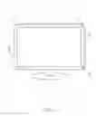
FIG. 1 is a schematic view of an exemplary embodiment of an LCD.
FIG. 2 is a circuit block diagram of the LCD of FIG. 1.
FIG. 3 is a flowchart of an exemplary embodiment of a display property adjusting method.
DETAILED DESCRIPTION
Referring to FIGS. 1 and 2, an exemplary embodiment of a liquid crystal display (LCD) 1 includes a main body 10 and a display circuit 20 positioned inside the main body 10. The display circuit 20 is used to automatically adjust display properties of the LCD 1 for accommodating eyes of users.
The main body 10 is approximately rectangular-shaped. First to fourth sensors 11-14 are mounted on four corners of the main body 10 correspondingly. An auto-adjusting switch 30 is mounted on a side of the main body 10. In other embodiments, the number of the sensors can be changed according to requirements. The sensors 11-14 and the auto-adjusting switch 30 can be mounted on other positions of the main body 10 according to requirements.
The display circuit 20 includes an optical signal collecting unit 15, a property saving unit 16, a property comparing unit 17, a property setting unit 18, and a graphic processor 19. It may be understood that the LCD 1 also includes other circuits, such as a power circuit, and a signal output circuits, for example. These circuits are well-known circuits, and so are not described here.
The first to fourth sensors 11-14 sense direction, intensity, and color of light around the LCD 1 and generate optical analog signals correspondingly. In detail, the first to fourth sensors 11-14 sense point light at the four corners of the main body 10. Two of the first to fourth sensors 11-14 sense line light between two corresponding corners of the main body 10. Three of the first to fourth sensors 11-14 sense surface light among three corresponding corners of the main body 10.
The optical signal collecting unit 15 is connected to the first to fourth sensors 11-14 to receive the optical analog signals (including the point optical signals, the line optical signals, and the surface optical signals) generated by the first to fourth sensors 11-14, and convert the optical analog signals into optical digital signals.
The property saving unit 16 saves a plurality of predetermined display properties (such as luminance properties, color properties, contrast properties) of the LCD 1 and a plurality of predetermined optical signal ranges (including point optical signal ranges, line optical signal ranges, and surface optical signal ranges) corresponding to the predetermined display properties.
The property comparing unit 17 receives the optical digital signals from the optical signal collecting unit 15 and compares the optical digital signals with the plurality of predetermined optical signal ranges. When the digital signals is in a corresponding predetermined optical signal range (e.g., a corresponding point optical signal range, a corresponding line optical signal range, and a corresponding surface optical signal range) is determined. Then, the corresponding predetermined display properties are selected by the property comparing unit 17 according to the determined optical signal range.
The property setting unit 18 receives the selected display properties and output the selected display properties to the graphic processor 19. The graphic processor 19 receives the selected display properties and correspondingly changes display properties of the LCD 1.
The auto-adjusting switch 30 is connected to the graphic processor 19 to switch the graphic processor 19 to be controlled by an automatic adjusting mode or a manual adjusting mode. When the graphic processor 19 works in the automatic adjusting mode, the graphic processor 19 receives the selected display properties and correspondingly adjusts display properties of the LCD 1. When the graphic processor 19 is in the manual adjusting mode, the graphic processor 19 does not receive the selected display properties. At this status, the LCD 1 can be adjusted by controlling some display switches mounted on the LCD 1. In other embodiments, the auto-adjusting switch 30 can be omitted to save costs.
Referring to FIG. 3, an exemplary embodiment of a display property adjusting method includes the following steps.
In step S1, a determination is made whether the automatic adjusting mode of the auto-adjusting switch 30 is actuated. If the automatic adjusting mode of the auto-adjusting switch 30 is actuated, the process goes to step S2. If the automatic adjusting mode of the auto-adjusting switch 30 is not actuated, the process ends. In other embodiments, if the auto-adjusting switch 30 is omitted, this step can be omitted correspondingly.
In step S2, the optical signal collecting unit 15 receives optical analog signals (including the point optical signals, the line optical signals, and the surface optical signals) generated by the first to fourth sensors 11-14, and converts the received optical analog signals into optical digital signals.
In step S3, the property comparing unit 17 receives the optical digital signals from the optical signal collecting unit 15 and compares the optical digital signals with the predetermined optical signal ranges stored in the property saving unit 16, and then select predetermined display properties corresponding to a predetermined optical signal range that the optical digital signals are located in.
In step S4, the property setting unit 18 receives the selected display properties and outputs the selected display properties to the graphic processor 19, to adjust display properties of the LCD 1.
Display properties of the LCD 1 cannot be adjusted automatically without having to manual operate display property controllers mounted on the LCD in a manual operation mode, which is very convenient.
It is to be understood, however, that even though numerous characteristics and advantages of the present disclosure have been set forth in the foregoing description, together with details of the structure and function of the disclosure, the disclosure is illustrative only, and changes may be made in details, especially in matters of shape, size, and arrangement of parts within the principles of the disclosure to the full extent indicated by the broad general meaning of the terms in which the appended claims are expressed.
Claims
What is claimed is:1. A liquid crystal display (LCD), comprising:
a main body;
a graphic processor, operable to adjust display properties of the LCD;
a plurality of sensors mounted on the main body of the LCD, to sense light around the LCD and generate optical analog signals correspondingly;
an optical signal collecting unit, operable to receive the optical analog signals generated by the plurality of sensors, and convert the optical analog signals into optical digital signals;
a property saving unit, operable to save a plurality of predetermined display properties of the LCD, and a plurality of predetermined optical signal ranges corresponding to the plurality of predetermined display properties;
a property comparing unit to receive the optical digital signals from the optical signal collecting unit and compare the optical digital signals with the predetermined optical signal ranges, and select corresponding predetermined display properties; and
a property setting unit to receive the selected display properties and output the selected display properties to the graphic processor to adjust display properties of the LCD.
2. The LCD of claim 1, wherein the plurality of sensors comprises four sensors mounted on four corners of the main body.
3. The LCD of claim 2, wherein the four sensors sense point light at the four corners of the main body, two of the four sensors sense line light between corresponding two corners of the main body, and three of the four sensors sense surface light among three corresponding corners of the main body.
4. The LCD of claim 1, wherein the predetermined display properties comprise luminance properties, color properties, and contrast properties of the LCD.
5. The LCD of claim 1, further comprising an auto-adjusting switch connected to the graphic processor to switch the graphic processor to be controlled by an automatic adjusting mode or a manual adjusting mode.
6. A display property adjusting method for adjusting display properties of a liquid crystal display (LCD), the LCD comprising a plurality of sensors to sense light around the LCD, the display property adjusting method comprising:
receiving optical analog signals generated by the plurality of sensors, and converting the received optical analog signals into optical digital signals;
receiving the optical digital signals and comparing the optical digital signals with a plurality of predetermined optical signal ranges saved in a property saving unit, and then selecting corresponding predetermined display properties saved in the property saving unit; and
receiving the selected display properties and outputting the selected display properties to a graphic processor of the LCD, to adjust display properties of the LCD.
Images & Drawings included:


Sources:
- United States Patent and Trademark Office - verify current appl. status at the USPTO↗
Recent applications in this class:
- » 20150106047 2015-04-16
Method for ground-to-satellite laser calibration system - » 20150015890 2015-01-15
Method and apparatus for optical asynchronous sampling signal measurements - » 20130224877 2013-08-29
Luminescence reference standards - » 20090190124 2009-07-30
Uniform light generating system for testing an image-sensing device and method of using the same - » 20060212240 2006-09-21
Sensor device - » 20060038113 2006-02-23
Photodetector arrangement and method for stray ligh compensation
Recent applications for this Assignee:
- » 20140233961 2014-08-21
Optical communication module including optical-electrical signal converters and optical signal generators - » 20140083669 2014-03-27
HEAT SINK - » 20140063746 2014-03-06
Electronic device with heat dissipation assembly - » 20140061224 2014-03-06
AUTOMATIC VENDING MACHINE - » 20140060914 2014-03-06
Enclosure with shield apparatus - » 20140058727 2014-02-27
MULTIMEDIA RECORDING SYSTEM AND METHOD - » 20140055955 2014-02-27
Fastener - » 20140055322 2014-02-27
DISPLAY SYSTEM AND HEAD-MOUNTED DISPLAY APPARATUS - » 20140054439 2014-02-27
CONTAINER DATA CENTER WITH SUPPORTING APPARATUS - » 20140054311 2014-02-27
AUTOMATIC VENDING MACHINE WITH MOVING MEMBER FOR PRODUCTS