Portable, lightweight folding stool and carrying case
US20100314919A1
2010-12-16
12/800,201
2010-05-12
Abstract:
The invention is of a PORTABLE, LIGHTWEIGHT FOLDING, STOOL AND CARRYING CASE. The stool frame is easily folded together and placed into the upholstered seat top, which when zippered together, acts as a carrying case. In this folded and enclosed form the stool becomes easily transportable to any location where seating is desired. The stool framework and seat top consists of the following basic elements:
- a) A center threaded shaft with a graspable handle surface at mid point.
- b) An upper and lower threaded locking bolt freely turning on the threaded shaft, above and below the center handle.
- c) A minimum of three seat support arms, hinge-connected to an upper pinning device, which is securely anchored to the upper end of the center, threaded shaft.
- d) A minimum of three lower legs, hinge-connected to a lower pinning device, which is securely anchored to the lower end of the center, threaded shaft.
- e) The upholstered seat-top sitting surface, which has pockets at the underside to receive and hold the outer ends of the upper seat support arms. The upholstered seat top has a zipper at the perimeter which, when folded and zippered together, becomes a carrying case to transport the folded stool frame. The upholstered seat top has a snap buckle attached at either side of the underside surface.
- f) For carrying the stool/carrying case, there is an attachable handle or adjustable shoulder strap.
- g) With the stool framework folded and inserted into the zippered seat top carrying case, the seating device is easily transported to a point of use or easily stored between uses.
Interested in similar patents?
Get notified when new applications in this technology area are published.
Classification:
A47C9/105 » CPC main
Stools for specified purposes; Camp, travelling, or sports stools having several foldable or detachable legs converging in one point
A47C9/10 IPC
Stools for specified purposes Camp, travelling, or sports stools
Description
PRIOR APPLICATION
This is the patent submission following granting of the Provisional Patent, Application No. 61/268,205 with Filing or 371 (c) date of Jun. 10, 2009 in the name of William Charles Jackson, Davidsonville, Md., 21035.
TECHNICAL FIELD
This invention relates in general to a portable stool/seat with foldable framework. This specific invention uses the upholstered top-sitting surface as the carrying case for the folded stool framework. The upholstered top sitting surface has a zipper or other attaching means applied to the perimeter edges which, when folded and zipped or otherwise attached together, becomes a carrying case for the folded framework.
BACKGROUND INFORMATION AND SUMMARY OF THE INVENTION
It is often desirable to have a portable, foldable, lightweight stool that is easily transported from one place to another and available for sitting upon in an unlimited variety of indoor and/or outdoor locations and occasions. It is also desirable that the stool be reduced to a small, lightweight package for the ease of conveying and storage. Many folding sitting devices have been developed in the past. The existing assortment of folding stools have been, to some extent, unstable, difficult to fold and unfold, heavy, and of comparatively large size when folded, making them not easily carried or stored between uses.
This invention provides a foldable, lightweight stool that is stable, very easily folded into a small size for carrying, and easily unfolded and set up for use. The invention has an upholstered top/sitting surface that, when folded and zippered together, doubles as a carrying case. The stool shown in detail here has three (3) legs and (3) upper seat support arms. The same basic design configuration can be manufactured with four (4) legs and upper seat support arms or five (5) legs and upper seat support arms. The same basic system for folding and unfolding will apply. The design with four (4) legs and arms, or the design with five (5) legs and arms will slightly increase the weight but will greatly increase the stability during the use of the stool. Increasing the number of legs and top seat support arms to four or five will also increase the carrying capacity/loading maximum, which the stool will support without failure.
BRIEF DESCRIPTION OF THE DRAWINGS
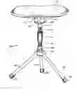
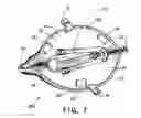
FIG. 1 is a perspective view of the PORTABLE, LIGHTWEIGHT, FOLDING STOOL AND CARRYING CASE in its fully assembled form, ready to be used as a seat.
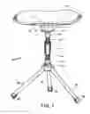
FIG. 2 is an elevation drawing showing the stool framework in set up and locked configuration. The upholstered seat surface is shown dotted. The drawing shows the folding direction of the upper seat support arm and the lower leg.
FIG. 3 is a plan drawing showing the arrangement of the three upper seat support arms and the three lower legs. There is a 60-degree angle between each upper and lower element, allowing each to fold inward without interference with any other element.
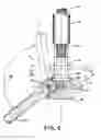
FIG. 4 is a plan drawing detail of the legs as they relate to the center shaft and the lower pinning unit, which holds the legs together and allows them to fold.
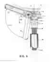
FIG. 5 is a partial section detail of the upper end of the center threaded shaft intersection with the upper pinning unit and the upper seat support arm.
FIG. 6 is a partial section detail of the lower end of the center threaded shaft intersection with the lower pinning unit and the lower leg.
FIG. 7 is a perspective view of the lightweight, portable, folding stool and carrying case with the stool framework folded and placed into the partially zippered together seat top, which becomes a carrying case for the folded frame.
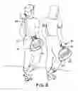
FIG. 8 is a perspective view of two persons carrying the folded stool frame and carrying case. The person at the right side of the view has the carrying case with the attached handle in place. The person at the left side of the perspective view has the carrying case with the attached, adjustable shoulder strap in place.
| LIST OF REFERENCE NUMBERS USED IN THE DRAWINGS |
| DETAILED DESCRIPTION | ||
| ITEM NUMBER | NAME ASSIGNED | OF THE ITEM |
| 10 | perspective view of invention | Perspective view of the stool |
| framework and upholstered top, | ||
| completely assembled and ready | ||
| for use as a seat. | ||
| 12 | upper hinge pin | Metal pin attached through the |
| closed end of the upper seat | ||
| support arm. | ||
| 13 | Fabric pocket located at the | |
| underside of the upholstered seat | ||
| top which is used to engage the | ||
| outer end of the upper seat support | ||
| arms. | ||
| This holds the seat top to the | ||
| frame. | ||
| 14 | upholstered seat top | Upholstered, fabric seat top with |
| zipper at perimeter edges. | ||
| When folded and zippered | ||
| together, it becomes the carrying | ||
| case for the folded stool | ||
| framework. | ||
| 15 | snap buckle | A two piece molded item with |
| each end of the snap buckle fixed | ||
| to a piece required to be attached | ||
| together. | ||
| 16 | upper pinning unit | A two-piece metal unit fabricated |
| to receive and hold the pin end of | ||
| the upper seat support arm 17. | ||
| 17 | upper seat support arm | Metal tubular arm held in place by |
| the upper pinning unit 16. | ||
| 18 | upper seat support arm | The dotted indication shows the |
| (shown dotted) | upper seat support arm 17 in the | |
| folded position. | ||
| 19 | upper locking bolt | A special bolt threaded to match |
| the center shaft thread. The bolt, | ||
| when rotated up toward the upper | ||
| pinning unit 16, will lock the | ||
| upper seat support arm 17 in | ||
| position. | ||
| 20 | upper locking bolt | The dotted indication shows the |
| (shown dotted) | upper locking bolt in unlocked | |
| position, allowing the upper seat | ||
| support arm to rotate into the | ||
| folded position 18. | ||
| 21 | arrow indication | The broken line/arrow indicates |
| the distance of travel of the upper | ||
| seat support arm 17 from locked | ||
| position to folded position 18. | ||
| 22 | zipper | The zipper attached to the |
| perimeter of the upholstered seat | ||
| top. | ||
| 23 | center threaded shaft | A hollow metal, threaded shaft |
| used for the center segment of the | ||
| stool framework. | ||
| 24 | center threaded shaft | This is the center threaded shaft |
| (shown dotted) | where it is in plan view, and | |
| where it is hidden below or above | ||
| the element attached to the center | ||
| shaft. | ||
| 25 | handle | The handle at the center shaft is |
| formed around the center shaft. | ||
| The handled has a non-slip | ||
| surface that can be easily gripped. | ||
| 26 | travel distance | The vertical travel distance of the |
| upper locking bolt is | ||
| approximately 1″ from locked | ||
| position to unlocked position. | ||
| 27 | end of center shaft | This is the upper end of the center |
| threaded shaft 23 which is firmly | ||
| anchored into the upper pinning | ||
| unit 16. | ||
| 28 | plane of reference | This is the plane of reference as |
| shown on plan drawing FIG. 3 at | ||
| the position from which elevation | ||
| drawing FIG. 2 is taken. | ||
| 29 | angle between elements | The angle between elements |
| where indicated on FIG. 3 for this | ||
| 3-leg/arm stool design in 60 | ||
| degrees. | ||
| The angle between elements for a | ||
| 4-leg/arm design is 45 degrees. | ||
| The angle between elements for a | ||
| 5-leg/arm design is 36 degrees. | ||
| 30 | lower locking bolt | A special bolt threaded to match |
| the center threaded shaft. | ||
| The bolt, when rotated down | ||
| toward the lower pinning unit 36, | ||
| will lock the lower leg 40 in | ||
| position. | ||
| 31 | lower locking bolt | The dotted indication shows the |
| (shown dotted) | lower locking bolt in unlocked | |
| position allowing the lower leg to | ||
| rotate up to the folded position 41. | ||
| 32 | travel distance | The vertical travel distance of the |
| lower locking bolt is | ||
| approximately 1″ from locked | ||
| position to unlocked position. | ||
| 33 | section cut line | The section cut line location is |
| indicated on FIG. 2 and FIG. 6. | ||
| It is the location along the center | ||
| threaded shaft 23 where the | ||
| section and plan in FIG. 4 is cut. | ||
| 36 | lower pinning unit | A two-piece metal unit fabricated |
| to receive and hold the pin end of | ||
| the lower leg 40. | ||
| 37 | lower hinge pin | A metal pin attached through the |
| closed end of the lower leg 40. | ||
| 38 | arrow indication | The broken line/arrow indicates |
| the distance of travel of the lower | ||
| leg 40, from locked position to | ||
| folded position 41. | ||
| 39 | end of center shaft | This is the lower end of the center |
| threaded shaft 23, which is firmly | ||
| anchored into the lower pinning | ||
| unit 36. | ||
| 40 | lower leg | A metal tubular leg held in place |
| by the lower pinning unit 36. | ||
| 41 | lower leg | The dotted indication shows the |
| (shown dotted) | lower leg 40 in the folded | |
| position. | ||
| 42 | molded foot | The molded foot material firmly |
| attached to the lower end of the | ||
| lower leg 40 to provide “non-slip” | ||
| condition in use. | ||
| 43 | carrying handle | A formed, easy grip surface with |
| two snap buckles for attaching to | ||
| the folded and zippered | ||
| upholstered seat top 14. This | ||
| configuration forms a carrying | ||
| case for the folded stool | ||
| framework 47. | ||
| 44 | adjustable shoulder strap | A woven fabric/plastic webbing |
| with adjustable length and two | ||
| snap buckles 15. | ||
| The strap is attached to the folded | ||
| and zippered, upholstered seat top | ||
| 14. This configuration forms a | ||
| carrying case for the folded stool | ||
| framework 47. | ||
| 45 | approximate fold line | This is the approximate fold line |
| in the upholstered seat top 14. | ||
| This is where the seat top is | ||
| folded prior to zippering in order | ||
| to become the carrying case for | ||
| the folded frame 47. | ||
| 46 | applied decoration | This is applied decoration to the |
| seat top surface of the upholstered | ||
| seat top. | ||
| It can be a sewn monogram | ||
| material or print/ink, paint or | ||
| stencil, applied to the outside/top | ||
| surface. | ||
| The decoration can be in the form | ||
| of sports logos, advertising, and/or | ||
| other promotions. | ||
| 47 | folded framework | This is the center threaded shaft |
| 23 with all upper seat support | ||
| arms 17 and all lower leg 40 | ||
| folded together against the center | ||
| shaft to form a compact unit for | ||
| stowing. | ||
| 50 | folded framework inserted into | This is pictured in FIG. 7. |
| carrying case. | The fully folded framework 47, is | |
| inserted into the partially zippered | ||
| together, upholstered seat top 14, | ||
| forming a carrying case for | ||
| efficient portage of the stool. | ||
DETAILED DESCRIPTION OF THE INVENTION
The PORTABLE, LIGHTWEIGHT FOLDING STOOL AND CARRYING CASE as shown in the drawings, FIG. 1 through FIG. 8 consists of an upholstered seat top 14 and folded framework 47. The framework consists of three upper seat support arm(s) 17 and three lower leg(s) 40 hinge-connected onto either end of the center threaded shaft 23. When it is desired that the stool framework be folded for stowing and/or transport, the operation requires loosening of the upper locking bolt 19 and the lower locking bolt 30 at the center threaded shaft 23, and folding the lower leg(s) 40 and upper seat support arm(s) 17 together, approximately parallel to the center shaft. The folded frame 47 is then placed in the zippered together upholstered seat top 14 and attached to a carrying handle 43 or an adjustable shoulder strap 44 for transportation.
As shown in FIG. 1, reference number 10, the complete assembled and locked unit is shown ready to use as a seat at any selected location. The metal seat framework is built around a center threaded shaft 23 with a center handle 25 located at approximately mid-point of the shaft. The surface of the handle 25 is covered with a non-slip exterior face to facilitate handholding. Threaded onto the center threaded shaft 23 and movable above the handle 25 is the upper locking bolt 19. Threaded onto the center threaded shaft 23 and movable below the handle 25 is the lower locking bolt 30. The purpose of the upper locking bolt 19 is to turn on the center threaded shaft 23, moving up in order to engage the adjacent lower surface of the upper pinning unit 16 and the inner end of the upper seat support arm 17, locking the upper seat support arm 17 in a somewhat horizontal position as illustrated in FIG. 5. The purpose of the lower locking bolt 30 is to turn on the center threaded shaft 23, moving down in order to engage the adjacent upper surface of the lower pinning unit 36 and the upper, inner end of the lower leg 40, locking the lower leg 40 in an angular position as illustrated in FIG. 6. With the upper seat support arm(s) 17 and the lower leg(s) 40 locked in place, the next task is to install the upholstered seat top 14. Open and completely unzip zipper 22 at the perimeter of the upholstered seat top 14. Place the open upholstered seat top 14 generally centered over the top of the stool frame with the surface containing the pocket(s) 13 in a down position. Engage and insert the end of each upper seat support arm 17 into the pocket 13 at the underside of the upholstered seat top 14. The stool configuration is now fully assembled as shown in FIG. 1, and ready for use as a seat. Place the framework on a suitable, generally horizontal surface, which will support the stool and person sitting upon the stool/seat.
Shown in FIG. 2 is an elevation drawing of the PORTABLE, LIGHTWEIGHT FOLDING STOOL AND CARRYING CASE. The plane of reference 28 for the elevation drawing is as indicated on FIG. 3. Beginning at the upper portion of the drawing, the upholstered seat top 14 is shown dotted in this drawing in order to indicate how the outer ends of the upper seat support arm 17 is formed flat to engage into the pocket 13 at the underside of the upholstered seat top 14. The snap buckle 15 is omitted in this drawing in order to clarify the upper seat support arm 17 and the engagement with the pocket 13 at the underside of the upholstered seat top 14. When the upper locking bolt 19 is rotated and moved down to the dotted position 20, the upper seat support arm 17 is allowed to swing down into the folded position 18 (shown dotted). When the lower locking bolt 30 is rotated and moved up to the dotted position 31, the lower leg is allowed to swing up in the into the folded position 41 (shown dotted). With both the upper seat support arm 17 and the lower leg 40 in folded position 18 and folded position 41, the stool framework becomes the folded framework 47 as indicated in FIG. 7.
Shown in FIG. 3 is a plan drawing of the stool framework. The dotted outline of the upholstered seat top 14 is indicated. Also shown dotted are the locations of the pocket 13 at underside of upholstered seat top 14. Also shown dotted is the attached snap buckle 15 location. The angle between element 29 indicated between the position of the upper seat support arm 17 and the lower leg 40, is 60 degrees. This is consistent at all locations between elements. The upper pinning unit 16 is shown in plan from above with the upper hinge pin 12 at the inner end of the upper seat support arm 17 shown dotted as the pin is contained and held within the upper pinning unit 16. The upper hinge pin 12 is a solid metal, round item built into and fixed into the flattened, formed end of the upper seat support arm 17. The center threaded shaft 24 (shown dotted) is because it is below the upper pinning unit 16 in this view. The approximate fold line 45 is indicated and is the fold location for the folding and zippering operation of the upholstered seat top 14 as the top is reconfigured to become the carrying case for holding and transporting the folded framework 47, as indicated in FIG. 7.
Shown in FIG. 4 is a larger scale plan drawing and section. The section cut line 33 is shown on FIG. 2 and FIG. 6. The inner ends of the lower leg 40 are indicated with lower hinge pin 37 shown dotted because the pin is contained within the configuration of the lower pinning unit 36. The lower hinge pin 37 is a solid metal round item built into and fixed into the flattened, formed end of the low leg 40. The lower pinning unit 36 is fabricated with adequate clearances to allow the lower leg 40 and lower hinge pin 37 to be contained within the lower pinning unit 36 while still allowing the lower leg 40 and pin to rotate when the leg is moved to a folded position as indicated at lower leg (shown dotted) 41, FIG. 2 and FIG. 6.
Shown in FIG. 5 is a large-scale section and detail indicating the configuration of the elements at the top end of the center threaded shaft 23. A portion of the upholstered seat top 14 is shown dotted at this drawing. The upholstered seat top 14 consists of two thickness of material with the center space between packed with soft, pliable filler as shown here. The inner end of the upper seat support arm 17 with the upper hinge pin 12 fixed into the formed, flattened end, is shown contained between the two segments of the upper pinning unit 16. The two segments of the upper pinning unit 16 are fabricated with adequate clearances to allow the upper seat support arm 17 and upper hinge pin 12 to be contained within the upper pinning unit 16 while still allowing the upper seat support arm 17 and pin to rotate to a folded position as indicated at upper seat support arm (shown dotted) 18. The travel distance of the upper seat support arm 17 from locked position to the folded position is indicated by broken line arrow indication 21. The upper locking bolt 19 is drawn in full side view in order to show the way in which the inner end of the upper seat support arm 17, which is notched, engages the top and sloped side of the upper locking bolt 19. When the upper locking bolt 19 is turned tight in the uppermost position fitting into the notch at the inner end of the upper seat support arm 17, the upper seat support arm 17 is fully locked into position to support a seated person on the stool framework and upholstered top. The end of center shaft 27 is the upper end of the center threaded shaft 23, which is firmly fixed into the upper pinning unit 16. The two segments of the upper pinning unit 16 are assembled together with recessed bolts (not shown). The upper locking bolt 19 shown in the locked position is also indicated in the unlocked position by upper locking bolt (shown dotted) 20. This is the bolt position prior to moving the upper seat support arm 17 down into the folded position upper seat support arm (shown dotted) 18. The center threaded shaft 23 and the handle 25 are partially shown here in greater detail.
Shown in FIG. 6 is a large-scale section and detail indicating the configuration of the elements at the bottom end of the center threaded shaft 23. The upper end of the lower leg 40 with the lower hinge pin 37 fixed into the formed, flattened end is shown contained between the two segments of the lower pinning unit 36. The two segments of the lower pinning unit 16 are fabricated with adequate clearances to allow the lower leg 40 and lower hinge pin 37 to be contained within the lower pinning unit 36 while still allowing the lower leg 40 and pin to rotate to a folded position as indicated at lower leg (shown dotted) 41. The travel distance of the lower leg 40 from locked position to the folded position is indicated by broken line arrow indication 38. The lower locking bolt 30 is drawn in full side view in order to show the way in which the upper end of the lower leg 40 which is notched, engages the bottom and sloped side of the lower locking bolt 30. When the lower locking bolt 30 is turned tight in the lowermost position fitting into the notch at the lower leg 40, the lower leg 40 is fully locked into position to support a seated person on the stool framework and upholstered top. The end of center shaft 39 is the lower end of the center threaded shaft 23, which is firmly fixed into the lower pinning unit 36. The two segments of the lower pining unit 36 are assembled together with recessed bolts (not shown). The lower locking bolt 30 shown in the locked position is also indicated in the unlocked position by lower locking bolt (shown dotted) 31. This is the bolt position prior to moving the lower leg 40 up into the folded position lower leg (shown dotted) 41. The center threaded shaft 23 and the handle 25 are partially shown here in greater detail.
Shown in FIG. 7 is the upholstered seat top 14 folded together at the approximately fold line 45 shown in FIG. 3, and partially zippered together to form the carrying case to contain and carry the folded framework 47. Shown also at the underside of the upholstered seat top 14 is the pocket 13. There are three pockets to accommodate and contain the outer ends of the upper seat support arm(s) 17 when the upholstered seat top 14 is placed on top of the unfolded and locked stool framework. Shown also is the snap buckle 15. There are two, one at either side of the underside of the upholstered seat top 14. Indicated also is the zipper located at the perimeter edge of the underside of the upholstered seat top 14. The zipper 22 in this view is shown partially zipped, closed. With the folded framework 47 placed inside, the zipper 22 would be fully zipped together forming the carrying case for the folded framework 47. The two snap buckle 15 will protrude out at the top of the carrying case in order to attach either the carrying handles 43 or the adjustable shoulder strap 44. With the upholstered seat top 14 fully zipped and the carrying handle 43 or the adjustable shoulder strap 44 attached into the snap buckle 15, the packed stool is ready for transport to any location desired or ready for storage between uses.
Shown at FIG. 8 is a perspective view depicting two persons carrying the LIGHTWEIGHT, PORTABLE, FOLDING STOOL AND CARRYING CASE. The stool framework is fully folded into the folded framework 47 position as shown in FIG. 7, deposited into the zippered, upholstered seat top 14 and attached to either the adjustable shoulder strap 44 or the carrying handle 43. In this configuration the lightweight, portable, folding stool and carrying case is complete and ready to be easily transported to any location desired for sitting. As indicated and shown at FIG. 8, the outer surfaces (the top surface when the stool is fully assembled) of the upholstered seat top 41 are available for decoration with or by several existing processes. The surface can be modified and decorated with embroidery, existing items can be attached via adhesive and/or heat seal or the surface can be coated with flexible paint type coatings which are currently applied to shirts and other apparel. This applied decoration 46 can take the form of advertising, sport logos, personalized names or slogans, etc. The potential use of the outer surfaces is almost endless.
DESCRIPTION OF THE FRAME UNFOLDING AND LOCKING PROCESS
Beginning with the folded framework 47 in a fully folded configuration, the unfolding, and locking process is as follows:
- a) Using the center handle 25, hold the folded framework 47 vertical with legs unfolding down into a fully open position.
- b) With the lower leg(s) 40 in a down/fully open position, turn the lower locking bolt 30 in a clockwise direction on the center threaded shaft 23 until the legs are locked tight in a down position (typically, approximately 1″ movement vertically of the locking bolt turning on the center threaded shaft).
- c) Invert the frame so that the upper seat support arm(s) 17 fall down into a fully open position.
- d) With the upper seat support arm(s) 17 in a down/fully open position, turn the upper locking bolt 19 in a clockwise direction on the center threaded shaft 23 until the arms are locked tight in a down position (typically, approximately 1″ movement vertically of the locking bolt turning on the center threaded shaft).
- e) With legs locked in a down position and seat support arms locked in an up position, set the framework on a generally horizontal, stable surface.
- f) Completely unzip and open the upholstered seat top unit 14 and place the outer end of the upper seat support arm(s) 17 into the pocket(s) 13 at the underside of the upholstered seat top 14.
- g) With you hand, press down on the center of the upholstered seat top 14 to make sure all upper seat support arm(s) 17 are fully engaged into the seat top pocket(s) 13.
- h) Sit down upon the portable, folding stool unit.
Claims
What is claimed:1) A portable, lightweight, stool/seat as follows:
a. A foldable, collapsible, metal or other framework which, when folded and doubled together, becomes small and compact.
b. A seat top, sitting surface, which doubles as a carrying case for the folded framework. The seat top is upholstered and contains a means for anchoring in place to the unfolded framework. The seat top has a zipper or other attachment means at the perimeter. The seat top/carrying case has a means for attaching a carrying handle or adjustable length shoulder strap.
c. When not in use as a stool/seat, the folded frame can be easily inserted into the seat top/carrying case and the case closed up together. With either the handle or shoulder strap attached, the frame and top combined is easily transported or stored between uses.
2) A portable, lightweight, stool/seat of claim 1) wherein the framework consists of a center shaft with means to hinge-attach a minimum of 3 legs at the bottom end and a minimum of 3 seat support arms at the top end. Said legs and seat support arms can be securely locked in place when used to support the seat top and/or a seated person or other. When in unlocked condition, said legs and seat support arms can be folded and collapsed together. Means for locking and unlocking is gained by special bolts or other, rotating or locking element at the center shaft portion of the framework.
3) A portable, lightweight stool/seat of claim 1) wherein the seat top is comprised of two surfaces of fabric permanently fixed together at the perimeter and filled in between with upholstering filler. Fixed at the perimeter of the seat top is one portion of a zipper or other attachment devise, positioned in order that when the top is folded together and zipped or attached, the seat top forms and becomes a carrying case or bag to contain the folded, collapsed framework.
4) A portable, lightweight, stool/seat of claim 1) wherein the seat top perimeter, in lieu of a zipper or other attachment means is fabricated with perimeter draw strings and fixing devise so that when pulled tight and fixed, the draw string closes the seat top/carrying case in bag configuration.
5) A portable, lightweight stool/seat top of claim 1) wherein the seat top/carrying case, in lieu of a zipper or other attachment means at the perimeter, is configured with VELCRO positioned at the perimeter so that when folded and doubled together, the seat top with VELCRO forms the carrying case described to contain and carry the folded stool framework.
Images & Drawings included:


Sources:
- United States Patent and Trademark Office - verify current appl. status at the USPTO↗
Recent applications in this class:
- » 20250143472 2025-05-08
FOLDABLE DEVICE - » 20240156269 2024-05-16
SEAT AND ASSEMBLY FOR A SEAT - » 20240041217 2024-02-08
FOLDABLE CHAIR - » 20230329444 2023-10-19
Folding seat support frame - » 20220183471 2022-06-16
Seat and assembly for a seat - » 20180035815 2018-02-08
Support apparatus, such as a seat, foldable and portable - » 20170099955 2017-04-13
FOLDABLE CHAIR - » 20160213154 2016-07-28
Chair with a tension-compression structure - » 20140312663 2014-10-23
BICYCLE SEAT CONVERTER - » 20140132037 2014-05-15
PORTABLE SEAT WITH STORAGE