Aluminum foil based hose
US20110017338A1
2011-01-27
12/741,870
2008-09-30
✅ Patent granted
US 9,234,610 B2
2016-01-12
WO; PCT/US2008/078287; 20080930
WO; WO2009/061566; 20090514
James Hook
Renner, Otto, Boisselle & Sklar, LLP
2032-07-25
Abstract:
An ultra low permeability fluid member for conveying a fluid (e.g., a hose, tube, etc.) having a metal vapor barrier layer (22) formed around an inner tube (14). The metal vapor layer (22) is formed from one or more metal strips (40a, 40b) having edge portions (44) that are bonded so as to seal the vapor barrier layer (22) preventing permeation of vapor.
Inventors:
- Nikhil Baxi 5 🇺🇸 Cordova, TN, United States
- Paul Alan Guess 1 🇺🇸 Covington, TN, United States
- Eugene A. Dianetti 1 🇺🇸 Collierville, TN, United States
Assignee:
- PARKER-HANNIFIN CORPORATION 1,052 🇺🇸 Cleveland, OH, United States
Applicant:
Interested in similar patents?
Get notified when new applications in this technology area are published.
Classification:
B23K2101/06 » CPC further
Articles made by soldering, welding or cutting; Tubular or hollow articles Tubes
B23K2103/10 » CPC further
Materials to be soldered, welded or cut; Non-ferrous metals or alloys Aluminium or alloys thereof
B23K20/24 IPC
Non-electric welding by applying impact or other pressure, with or without the application of heat, e.g. cladding or plating Preliminary treatment
B23K20/10 IPC
Non-electric welding by applying impact or other pressure, with or without the application of heat, e.g. cladding or plating making use of vibrations, e.g. ultrasonic welding
B21C37/154 » CPC further
Manufacture of metal sheets, bars, wire, tubes or like semi-manufactured products, not otherwise provided for; Manufacture of tubes of special shape of tubes or metal hoses; Combined procedures for making tubes, e.g. for making multi-wall tubes; Making tubes of special shape; Making tube fittings Making multi-wall tubes
F16L11/085 » CPC main
Hoses, i.e. flexible pipes made of rubber or flexible plastics with reinforcements embedded in the wall comprising one or more braided layers
B32B25/16 » CPC further
Layered products comprising natural or synthetic rubber comprising polydienes or poly-halodienes
B32B15/06 » CPC further
Layered products comprising a layer of metal comprising metal as the main or only constituent of a layer, next to another layer of a of natural rubber or synthetic rubber
B32B15/08 » CPC further
Layered products comprising a layer of metal comprising metal as the main or only constituent of a layer, next to another layer of a of synthetic resin
B32B15/20 » CPC further
Layered products comprising a layer of metal comprising aluminium or copper
B32B25/10 » CPC further
Layered products comprising natural or synthetic rubber next to a fibrous or filamentary layer
F16L9/147 » CPC further
Rigid pipes; Compound tubes, i.e. made of materials not wholly covered by any one of the preceding groups comprising only layers of metal and plastics with or without reinforcement
B32B2262/0269 » CPC further
Composition or structural features of fibres which form a fibrous or filamentary layer or are present as additives; Synthetic macromolecular fibres; Polyamide fibres Aromatic polyamide fibres
B32B2262/0276 » CPC further
Composition or structural features of fibres which form a fibrous or filamentary layer or are present as additives; Synthetic macromolecular fibres Polyester fibres
B32B2262/103 » CPC further
Composition or structural features of fibres which form a fibrous or filamentary layer or are present as additives; Inorganic fibres Metal fibres
B32B2307/7242 » CPC further
Properties of the layers or laminate; Other properties; Permeability to gases, adsorption Non-permeable
B32B2307/7244 » CPC further
Properties of the layers or laminate; Other properties; Permeability to gases, adsorption; Non-permeable Oxygen barrier
B32B2597/00 » CPC further
Tubular articles, e.g. hoses, pipes
B32B2605/00 » CPC further
Vehicles
F16L2011/047 » CPC further
Hoses, i.e. flexible pipes made of rubber or flexible plastics with a diffusion barrier layer
F16L11/00 IPC
Hoses, i.e. flexible pipes
F16L11/08 IPC
Hoses, i.e. flexible pipes made of rubber or flexible plastics with reinforcements embedded in the wall
B21C37/08 » CPC further
Manufacture of metal sheets, bars, wire, tubes or like semi-manufactured products, not otherwise provided for; Manufacture of tubes of special shape of tubes or metal hoses; Combined procedures for making tubes, e.g. for making multi-wall tubes Making tubes with welded or soldered seams
B21C37/15 IPC
Manufacture of metal sheets, bars, wire, tubes or like semi-manufactured products, not otherwise provided for; Manufacture of tubes of special shape of tubes or metal hoses; Combined procedures for making tubes, e.g. for making multi-wall tubes Making tubes of special shape; Making tube fittings
B21F19/00 » CPC further
Metallic coating of wire
B23K31/02 » CPC further
Processes relevant to this subclass, specially adapted for particular articles or purposes, but not covered by only one of the preceding main groups relating to soldering or welding
B32B1/08 » CPC further
Layered products having a general shape other than plane Tubular products
B32B7/12 » CPC further
Layered products characterised by the relation between layers; Layered products characterised by the relative orientation of features between layers, or by the relative values of a measurable parameter between layers, i.e. products comprising layers having different physical, chemical or physicochemical properties; Layered products characterised by the interconnection of layers; Interconnection of layers using interposed adhesives or interposed materials with bonding properties
B32B15/02 » CPC further
Layered products comprising a layer of metal Layer formed of wires, e.g. mesh
B32B3/02 » CPC further
Layered products comprising a layer with external or internal discontinuities or unevennesses, or a layer of non-planar form ; Layered products having particular features of form characterised by features of form at particular places, e.g. in edge regions
B32B3/18 » CPC further
Layered products comprising a layer with external or internal discontinuities or unevennesses, or a layer of non-planar form ; Layered products having particular features of form characterised by a discontinuous layer, i.e. formed of separate pieces of material characterised by an internal layer formed of separate pieces of material which are juxtaposed side-by-side
F16L11/04 IPC
Hoses, i.e. flexible pipes made of rubber or flexible plastics
Description
RELATED APPLICATIONS
This application claims the benefit of U.S. Provisional Application No. 60/986,106 filed Nov. 7, 2007, which is hereby incorporated herein by reference.
FIELD OF THE INVENTION
The present invention relates generally to hoses, and more particularly to ultra-low permeation hoses.
BACKGROUND OF THE INVENTION
Low permeation hoses are often used in systems to eliminate or reduce escape and/or infiltration of vapors and/or gases. For example, such hoses may be used in refrigeration systems to prevent leakage of refrigerant vapors from the system into the environment. Such hoses are also common in fuel systems for preventing fuel vapors from escaping to the environment.
Another application of such hoses is in connection with heating systems for supplying and returning water (or other fluid) from one or more heat exchangers. In such applications, low permeation hoses are used to prevent oxygen from entering the heating system, which can result in corrosion of various components such as pumps and valves.
Low permeation hoses typically include an inner tube for carrying a fluid, and a vapor barrier layer surrounding the inner tube. Various other layers typically may surround the vapor barrier layer, such as a braiding, an outer tube, a cover or outer sheath, etc.
One type of hose that includes a metal foil as the vapor barrier layer is disclosed in U.S. Pat. No. 6,074,717. This patent describes a flexible hose including an inner tube, an aluminum vapor barrier layer formed from aluminum foil that is wrapped in overlapping fashion around the inner tube, and an outer tube surrounding the aluminum barrier layer. The aluminum barrier layer is bonded to both the inner tube and the outer tube. While this design may provide a hose that resists delamination of the tubes and/or the aluminum layer, the wrapped aluminum forming the barrier layer does not provide a continuous sealed barrier layer.
SUMMARY OF THE INVENTION
At least one embodiment of the invention provides a hose member for conveying fluid comprising a first tubular layer, a metal vapor barrier layer formed by at least one strip of metal surrounding the first tubular layer, and a second tubular layer surrounding the metal tubular layer, wherein the at least one metal strip has edge portions joined together to form at least one seam, and wherein the at least one seam is folded over a portion of the metal strip adjacent the seam.
At least one embodiment of the invention provides a method of making a hose comprising providing a first tubular layer forming a conduit for the flow of fluid, forming a metal barrier layer with at least one strip of metal surrounding the first tubular layer, the metal barrier layer having at least one radially outwardly extending seam running in the longitudinal direction of the hose that is folded over a portion of the metal strip adjacent the seam, and providing a second tubular layer surrounding the metal barrier layer.
At least one embodiment of the invention provides a hose member for conveying fluid comprising a first tubular layer, a metal vapor barrier layer surrounding the first tubular layer, the metal vapor barrier layer formed as a metal tube having at least one longitudinal seam formed radially outward from the metal tube, the longitudinal seam folded over a portion of the metal tube adjacent the longitudinal seam, and a second tubular layer surrounding the tubular metal vapor barrier layer.
Further features of the invention will become apparent from the following detailed description when considered in conjunction with the drawings.
BRIEF DESCRIPTION OF THE DRAWINGS
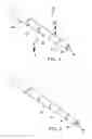
FIG. 1 is a perspective cut-away view of an exemplary fluid member in accordance with the invention.
FIG. 2 is a perspective cut-away view of another exemplary fluid member in accordance with the invention.
FIG. 3 is a perspective cut-away view of the fluid member of FIG. 1 in a partially formed state.
FIG. 4 is a cross-sectional view taken along the line 4-4 in FIG. 1.
FIG. 5 is a cross-sectional view taken along the line 4-4 in FIG. 1 of an alternative embodiment.
DETAILED DESCRIPTION
Referring to the drawings in detail, and initially to FIGS. 1 and 2, a fluid member for conveying fluid in accordance with the invention is generally indicated by reference numeral 10. The fluid conduit member 10, which in the illustrated embodiments is in the form of a hose (but may also be a tube, pipe, etc.), includes a first tubular layer 14 surrounding an interior passage 18 through which fluid can flow. A metal vapor barrier layer 22 surrounds the first tubular layer 14. The first tubular layer 14 can be composed of any suitable material, such as an elastomer that promotes bonding of the metal vapor barrier layer 22, as will be described below.
The metal vapor barrier layer 22 can be made of any suitable metal, such as aluminum. As will be described in more detail below, the metal vapor barrier layer 22 is formed by at least one strip of metal that is formed around the first tubular layer 14 and sealed, such as by welding, so as to form a generally continuous sealed vapor barrier layer. A second tubular layer 26 surrounds the metal vapor barrier layer 22, followed by a braided layer 30 for reinforcement (polyester/metallic wire, Kevlar, or any other suitable braid), and a cover 34. The first and/or second tubular layers 14 and 26 can be bonded to the metal vapor barrier layer 22. As shown in FIG. 2, the hose 10′ may further comprise additional layers such as an inner tubular layer 24 comprising a composite material or other suitable material. Other layers can also be provided between or in addition to the illustrated layers without departing from the scope of the invention.
Turning now to FIG. 3, the hose 10 of FIG. 1 is illustrated in a partially formed state wherein the metal vapor barrier layer 22 is being formed around the first tubular layer 14. While the following description refers to the hose 10 of FIG. 1, it will be appreciated that it is equally applicably to the hose of FIG. 2. In the embodiment of FIG. 3, the metal vapor barrier layer 22 is generally tubular and is formed by a pair of metal strips 40a and 40b that are pressed, rolled, or otherwise made to conform with an outer surface of the first tubular layer 14, or other layer as the case may be. The metal strips 40a and 40b can be aluminum foil, for example, and can be preformed into a suitable shape and applied to surround the first tubular layer 14, or may be formed to surround the first tubular layer 14 during application thereto.
Each metal strip 40a and 40b has opposite edge portions 44 that extend generally radially outwardly with respect to the longitudinal axis of the hose 10. Opposite edge portions from each metal strip 40a and 40b overlap respective opposite edge portions 44 of the other strip to form a pair of seams 48 that are generally diametrically opposed, but can be located in other positions about the circumference of the barrier layer 22 as desired.
The seams 48 typically will be bonded so as to seal the metal strips 40a and 40b together to form a continuous, sealed barrier layer. While merely folding the seams 48 (e.g., folding the seam in half, crimping the seam, etc) can achieve a suitable bond between the respective strips 40a and 40b, the radially outwardly extending seams 48 are well-suited for welding by a suitable welding apparatus, as will now be described.
As illustrated in FIG. 3, the radially outwardly extending seams 48 can be readily passed through an ultrasonic welding device 54 to bond the strips 40a and 40b together. By welding the seams 48, the metal vapor barrier layer 22 is effectively sealed around the circumference of the first tubular layer 14. The seams 48 can be bonded in other manners, such as with a suitable adhesive or via other suitable welding processes.
After the seams 48 are formed and/or bonded, each radially extending seam 48 is then folded over a portion 52 of one of the metal strips 40a or 40b that is adjacent each respective seam 48. As such, the seams 48 lie generally flat against the metal vapor barrier layer and follow its tubular contour.
For example, with reference to FIG. 4, which is a cross-section of the hose 10, the seams 48 are illustrated in a folded configuration. In this embodiment, the seams 48 extend in a common direction (e.g., clockwise) and are folded over portions 52 of the metal strips 40a and 40b adjacent the respective seams 48. In an alternative arrangement, illustrated in FIG. 5, the seams 48 extend in opposing directions. The seams 48 in FIGS. 4 and 5 are spaced apart from the adjacent portions 52 of the metal strips 40a and 40b for clarity, but in practice will generally be in contact with the portions 52.
In some applications, it may be desired to bond the seams 48 to the portions 52 of the metal strips 40a and/or 40b adjacent the seams 48. Accordingly, a suitable bonding agent 60 (FIG. 3), such as an adhesive, may be applied to the seams 48 and/or the adjacent portions 52 of the metal strips 40a and 40b prior to folding the seams 48. Alternatively, the seams 48 can be ultrasonically welded to the metal barrier layer 22 after folding. Bonding the seams 48 to the metal strips 40a and/or 40b can result in a more durable hose 10, and can prevent potential leakage from end faces of the hose 10 ensuring long-term performance.
Once the metal vapor barrier layer 22 and the second tubular layer 26 are in place, the metal vapor barrier layer 22 can be bonded to the first and/or second tubular layers 14 and 26. In this regard, the elastomer layers surrounding the metal vapor barrier layer 22, which can be ethylene propylene diene monomer (EPDM) rubber or other suitable material, may be blended with an additive to promote bonding with the metal vapor barrier layer material during subsequent curing of the elastomer layers, such as by vulcanization.
The above-described fluid members are particularly well-suited for commercial and automotive refrigeration systems, as well as air conditioning systems found in agriculture and off-highway vehicles, for example. Examples of such systems include high and low pressure R410 refrigerant or equivalent systems (e.g., residential applications), high and low pressure R134a refrigerant or equivalent systems (e.g., mobile applications), and/or high and low pressure R477 refrigerant or equivalent systems (e.g., mobile applications). The fluid members can be used in a wide variety of other systems as well, including other conventional and future refrigerant systems.
Although the invention has been shown and described with respect to a certain preferred embodiment or embodiments, it is obvious that equivalent alterations and modifications will occur to others skilled in the art upon the reading and understanding of this specification and the annexed drawings. In particular regard to the various functions performed by the above described elements (components, assemblies, devices, compositions, etc.), the terms (including a reference to a “means”) used to describe such elements are intended to correspond, unless otherwise indicated, to any element which performs the specified function of the described element (i.e., that is functionally equivalent), even though not structurally equivalent to the disclosed structure which performs the function in the herein illustrated exemplary embodiment or embodiments of the invention. In addition, while a particular feature of the invention may have been described above with respect to only one or more of several illustrated embodiments, such feature may be combined with one or more other features of the other embodiments, as may be desired and advantageous for any given or particular application.
Claims
What is claimed is:1. A hose member for conveying fluid comprising:
a first tubular layer;
a metal vapor barrier layer formed by at least one strip of metal surrounding the first tubular layer; and
a second tubular layer surrounding the metal vapor barrier layer;
wherein the at least one metal strip has edge portions joined together to form at least one seam, and wherein the at least one seam is folded over a portion of the metal strip adjacent the seam.
2. A hose member as set forth in any preceding claim, wherein the at least one metal strip includes a pair of metal strips surrounding respective halves of the first tubular layer, and wherein each metal strip has opposite edge portions overlapping respective opposite edge portions of the other strip to form a pair of seams.
3. A hose member as set forth in any preceding claim, wherein the at least one seam is welded.
4. A hose member as set forth in any preceding claim, wherein the at least one seam is ultrasonically welded.
5. A hose member as set forth in any preceding claim, wherein at least a portion of the seam is bonded to a portion of the metal strip adjacent the seam.
6. A hose member as set forth in any preceding claim, wherein the metal vapor barrier layer is bonded to at least one of the first tubular layer and second tubular layer.
7. A hose member as set forth in any preceding claim, wherein the metal strip is aluminum foil.
8. A method of making a hose comprising:
providing a first tubular layer forming a conduit for the flow of fluid;
forming a metal vapor barrier layer with at least one strip of metal surrounding the first tubular layer, the metal vapor barrier layer having at least one radially outwardly extending seam running in the longitudinal direction of the hose that is folded over a portion of the metal strip adjacent the seam; and
providing an second tubular layer surrounding the metal vapor barrier layer.
9. A method as set forth in any preceding claim, wherein the metal vapor barrier layer is formed with a pair of metal strips surrounding respective halves of the first tubular layer, and wherein each metal strip has opposite edge portions overlapping respective opposite edge portions to form a pair of seams.
10. A method as set forth in any preceding claim, further comprising welding the at least one seam.
11. A method as set forth in any preceding claim, further comprising ultrasonically welding the at least one seam.
12. A method as set forth in any preceding claim, further comprising bonding at least a portion of the seam to a portion of the metal strip adjacent the seam.
13. A method as set forth in any preceding claim, further comprising providing a braid layer outside of the second tubular layer.
14. A method as set forth in any preceding claim, further comprising bonding the metal barrier layer to at least one of the first tubular layer and the second tubular layer.
15. A method as set forth in any preceding claim, wherein the bonding includes vulcanization.
16. A hose made by the method of any preceding claim.
17. A hose member for conveying fluid comprising:
a first tubular layer;
a metal vapor barrier layer surrounding the first tubular layer, the metal vapor barrier layer formed as a metal tube having at least one longitudinal seam formed radially outward from the metal tube, the longitudinal seam folded over a portion of the metal tube adjacent the longitudinal seam; and
a second tubular layer surrounding the metal vapor barrier layer.
18. A hose member as set forth in any preceding claim, wherein the metal vapor barrier layer is formed from a pair of metal strips surrounding respective halves of the first tubular layer, and wherein each metal strip has opposite edge portions overlapping respective opposite edge portions of the other strip to form a pair of seams.
19. A hose member as set forth in any preceding claim, wherein the at least one seam is welded.
20. A hose member as set forth in any preceding claim, wherein the at least one seam is ultrasonically welded.
21. A hose member as set forth in any preceding claim, wherein at least a portion of the seam is bonded to a portion of the metal tube adjacent the seam.
22. A hose member as set forth in any preceding claim, wherein the metal vapor barrier layer is bonded to at least one of the first tubular layer and second tubular layer.
23. A hose member as set forth in any preceding claim, wherein the metal barrier layer is aluminum foil.
Images & Drawings included:


Sources:
- United States Patent and Trademark Office - verify current appl. status at the USPTO↗
Similar patent applications:
- » 20120159985
FORMED ALUMINUM FOIL BASED HOSE
Recent applications in this class:
- » 20250137559 2025-05-01
SUSTAINABLE INDUSTRIAL HOSE - » 20250092967 2025-03-20
Tubular Irrigation Device and Method of Making the Same - » 20250035240 2025-01-30
VENEER TYPE TUBE OR HOSE WITH DIFFUSION BARRIER - » 20240229981 2024-07-11
MEDICAL TUBING - » 20240159332 2024-05-16
High-pressure hose of pressure washer and pressure washer - » 20240035595 2024-02-01
Reinforced recyclable flexible hose - » 20230366491 2023-11-16
Flat flexible hose for transporting fluids - » 20230366490 2023-11-16
TUBE ASSEMBLY AND METHOD OF FORMING SAME - » 20230323983 2023-10-12
HIGH STRENGTH MULTI-USE HOSE - » 20230160502 2023-05-25
HOSE, HOSE ARRANGEMENT AND CORRESPONDING PROCESS FOR MANUFACTURING A HOSE ARRANGEMENT
Recent applications for this Assignee:
- » 20250294714 2025-09-18
HEAT SINK WITH PIN FINS AND NON-STRAIGHT CONSTANT VOLUME FLOW CHANNEL - » 20250271091 2025-08-28
HEATER HOSE WITH MULTI-VOLTAGE FUNCTIONALITY AND CONSTANT POWER OUTPUT - » 20250260342 2025-08-14
BIDIRECTIONAL ISOLATED AC-DC CONVERTER - » 20250256226 2025-08-14
Variable Filter Media Thickness for Improved Flow and Filter Performance - » 20250237586 2025-07-24
NON-DESTRUCTIVE TESTING OF CARBON BRAKE DISKS - » 20250207666 2025-06-26
ELECTRICALLY CONDUCTIVE SEALING ELEMENT - » 20250179999 2025-06-05
VARIABLE DISPLACEMENT HYDRAULIC PUMP SYSTEM WITH OVER-TEMPERATURE PREVENTION - » 20250163773 2025-05-22
Fracking Plug with a Support Ring - » 20250163772 2025-05-22
Fracking plug with a telescopic cone configuration - » 20250105730 2025-03-27
BIDIRECTIONAL ISOLATED HIGH VOLTAGE DC-DC CONVERTER