Method For Vaporizing Cryogenic Liquid Through Heat Exchange Using Calorigenic Fluid
US20110017429A1
2011-01-27
12/933,571
2009-03-12
Abstract:
A method of vaporizing cryogenic liquid, for example liquefied natural gas, by heat exchange with a calorigenic fluid, for example gaseous nitrogen is provided.
Inventors:
- Alain Briglia 21 🇫🇷 Corze, France
- Philippe GRIGOLETTO 8 🇫🇷 Villeparisis, France
- Marc Wagner 32 🇫🇷 Saint Maur Des Fosses, France
- Daniel MACHON DIEZ DE BALDEON 3 🇫🇷 Paris, France
- Maurice Bosquain 1 🇫🇷 Sommecaise, France
Interested in similar patents?
Get notified when new applications in this technology area are published.
Classification:
F17C9/02 » CPC main
Methods or apparatus for discharging liquefied or solidified gases from vessels not under pressure with change of state, e.g. vaporisation
F17C7/04 » CPC further
Methods or apparatus for discharging liquefied, solidified, or compressed gases from pressure vessels, not covered by another subclass; Discharging liquefied gases with change of state, e.g. vaporisation
F25J5/002 » CPC further
Arrangements of cold exchangers or cold accumulators in separation or liquefaction plants for continuously recuperating cold, i.e. in a so-called recuperative heat exchanger
F28D9/00 » CPC further
Heat-exchange apparatus having stationary plate-like or laminated conduit assemblies for both heat-exchange media, the media being in contact with different sides of a conduit wall
F28F3/005 » CPC further
Plate-like or laminated elements; Assemblies of plate-like or laminated elements Arrangements for preventing direct contact between different heat-exchange media
F17C2227/0309 » CPC further
Transfer of fluids, i.e. method or means for transferring the fluid; Heat exchange with the fluid; Heat exchange with the fluid by heating using another fluid
F17C2265/05 » CPC further
Effects achieved by gas storage or gas handling Regasification
F25J2210/62 » CPC further
Processes characterised by the type or other details of the feed stream Liquefied natural gas [LNG]; Natural gas liquids [NGL]; Liquefied petroleum gas [LPG]
F25J2250/42 » CPC further
Details related to the use of reboiler-condensers; External or auxiliary boiler-condenser in general, e.g. without a specified fluid or one fluid is not a primary air component or an intermediate fluid One fluid being nitrogen
F25J2290/90 » CPC further
Other details not covered by groups - Details about safety operation of the installation
F28D2021/0033 » CPC further
Heat-exchange apparatus not covered by any of the groups - ; Other heat exchangers for particular applications; Heat exchange systems not otherwise provided for for cryogenic applications
F28D15/00 IPC
Heat-exchange apparatus with the intermediate heat-transfer medium in closed tubes passing into or through the conduit walls ; Heat-exchange apparatus employing intermediate heat-transfer medium or bodies
F28D15/00 IPC
Heat-exchange apparatus employing intermediate heat-transfer media or bodies
Description
The present invention relates to a method of vaporizing cryogenic liquid, for example liquefied natural gas, by heat exchange with a calorigenic fluid, for example gaseous nitrogen.
In order to heat up and vaporize cryogenic liquids of the liquefied natural gas (LNG) or equivalent type against a calorigenic fluid, in order to recover the cold energy from the LNG, use has, in the past, been made of one of the following three options:
-
- a technology that consists in coiling into the form of a pancake coil a system comprising two tubes that are joined together by a tie. The tubes are welded or expanded onto manifolds transverse to the pancake coils;
- brazed plate and fin exchangers;
- wound tubular exchangers.
If there is a wish to recover the cold energy in order to liquefy air gases, it is absolutely essential to avoid accidental contamination of the nitrogen or the oxygen with a hydrocarbon gas, especially when the natural gas is circulating through the exchanger at a pressure higher than that of the air gas.
Tubular geometries are not very thermally efficient and often lead to costly over engineering.
Moreover, existing methane terminals and existing air separation plants do not always have the equipment required to avoid sharp thermal transients during shut downs and restarts, and this leads to thermal shock and therefore damage to the exchangers.
One subject of the invention is a method for heating up a first fluid by heat exchange with a second fluid in a plate and fin heat exchanger in which the first fluid is heated up in a first series of separated passages and the second fluid is cooled down in a second series of separated passages, characterized in that each passage of the first series is separated from the nearest passage of the second series by an auxiliary passage containing fins in which an inert gas circulates.
Optionally:
-
- the first fluid consists of liquefied natural gas which is vaporized or heated up in the first series of separated passages;
- the second fluid consists of gaseous nitrogen which is cooled down or liquefies in the second series of separated passages;
- the inert gas is at a pressure of at least 0.1 bar or even at least 0.5 bar higher than those of the first fluid and of the second fluid;
- the inert gas is at a pressure of at least 0.1 bar, or even at least 0.5 bar lower than those of the first fluid and of the second fluid;
- the inert gas is gaseous nitrogen;
- the inert gas sent into at least certain auxiliary passages is then sent to the atmosphere or to a flare;
- at least one inlet and/or outlet box of one of the first and second fluids is separated from the passages in which the other of the first and second fluids circulates by means of a double bar system, the bars possibly being separated by a dead zone;
- the first fluid is heated up at a pressure of at least 60 bar abs.
Another subject of the invention is a method of starting a plate and fin heat exchanger in which, at full capacity, a first fluid is heated up by heat exchange with a second fluid in a plate and fin heat exchanger, the first fluid being heated up in a first series of separated passages and the second fluid being cooled down in a second series of separated passages, characterized in that each passage of the first series is separated from the nearest passage of the second series by an auxiliary passage containing fins and in which during start-up an inert gas at a temperature lower than ambient temperature, possibly at cryogenic temperature, is sent into at least one auxiliary passage in order to get down to temperature more swiftly.
The invention will be described in greater detail with reference to the figures.
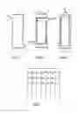
FIGS. 1 to 3 show a cross section, taken in the lengthwise direction of the exchanger, of each type of passage for an exchanger operating in accordance with the invention. FIG. 1 depicts an auxiliary, inert gas passage, FIG. 2 an LNG passage, and FIG. 3 a passage for nitrogen that is to be heated.
FIGS. 4 to 6 depict another exchanger operating in accordance with the invention. FIG. 4 shows a cross section through the parallel passages of the exchanger in the widthwise direction of the exchanger, FIG. 5 shows a low-pressure nitrogen passage sectioned in its lengthwise direction and FIG. 5 shows an LNG passage section in its lengthwise direction. According to the invention, a passage of the type of FIG. 1 will be positioned between each passage of the type of FIG. 2 and each type of FIG. 3. Thus, each passage of series of the type of FIG. 2 is separated from each passage of the series of the type of FIG. 3 by a passage of the type of FIG. 1 to form a brazed plate and fin exchanger made of aluminum or some other material. In order to simplify the drawing, the fins have not been illustrated.
FIG. 1 is the auxiliary, low-pressure inert gaseous nitrogen passage, the inlet 9 of which is bottom right and the outlet 11 of which is top left.
FIG. 2 illustrates a passage for heating up liquefied natural gas (LNG) which enters the passage at bottom left 1 and emerges top right 3. A double bar isolates the top and the bottom of the LNG passage from the inert nitrogen passage.
FIG. 3 shows a passage for the cooling of high-pressure gaseous nitrogen which enters the top of the passage through the inlet 7 and emerges at the bottom through the outlet 5. The high-pressure gaseous nitrogen passage is not as wide as the low-pressure nitrogen passages of FIG. 1 or as the liquefied natural gas passages of FIG. 2.
To avoid the nitrogen becoming contaminated with the liquefied natural gas, an auxiliary passage is interposed between each pair of nitrogen and LNG passages. The exchange of heat between the nitrogen and LNG passages will be via the fins of the auxiliary passage, by conduction. Obviously, the corrugation chosen for the auxiliary passage will have an optimal height/thickness ratio.
In the case illustrated, the auxiliary passages will be swept with low-pressure gaseous nitrogen (at a pressure lower than that of the LNG of FIG. 2 and than that of the nitrogen of FIG. 3) and collected for discharging to the atmosphere or possibly to a flare.
The boxes which cover the stack and may therefore be sources of contamination, will therefore be isolated from the other fluid using dead zones Z.
Gas from the dead zones Z will be collected, and these zones may possibly be swept with low-pressure nitrogen.
The above dead zones may be isolated from the LNG and nitrogen circuits by means of a double bar 2 system in order to improve sealing. Gases from the clearance space between the double bars 2 may itself be collected in order to improve intrinsic safety. This is explained in greater detail in respect of the method of FIGS. 5 and 6 but applies equally to the method of FIGS. 1 to 3.
The passages of FIG. 1 are used during start-ups to bring the exchanger down to temperature gradually and in a controlled manner using a flow of low-pressure nitrogen drawn from an auxiliary volume.
According to another aspect of the invention which is illustrated in FIG. 4, each passage for nitrogen that is to be heated up (N2 LP) is isolated from the passages for LNG to be vaporized by a passage containing a high-pressure inert process gas (N2 HP), in this case nitrogen at a higher pressure than the nitrogen that is to be heated up (35 bar) and than the liquefied natural gas that is to be vaporized (15 bar).
As can be seen in FIGS. 5 and 6, the bars which separate a circuit for nitrogen that is to be heated up from an LNG circuit are duplicated so that the space between them forms a dead zone Z open to the atmosphere via a vent V, so that any leak of liquefied natural gas can escape via this route. The passages in FIGS. 5 and 6 are separated by a high-pressure inert gas passage.
Claims
1-10. (canceled)
11. A method for heating up a first fluid by heat exchange with a second fluid in a plate and fin heat exchanger in which the first fluid is heated up in a first series of separated passages and the second fluid is cooled down in a second series of separated passages, comprising:
separating each passage of the first series from the nearest passage of the second series by an auxiliary passage containing fins in which an inert gas circulates.
12. The method of claim 11, wherein the first fluid consists of liquefied natural gas which is heated in the first series of separated passages.
13. The method of claim 11, wherein the first fluid consists of liquefied natural gas which is vaporized in the first series of separated passages.
14. The method of claim 11, wherein the second fluid consists of gaseous nitrogen which cools in the second series of separated passages.
15. The method of claim 11, wherein the second fluid consists of gaseous nitrogen which liquefies in the second series of separated passages.
16. The method of claim 11, wherein the inert gas is at a pressure at least 0.1 bar higher than those of the first fluid and of the second fluid.
17. The method of claim 11, wherein the inert gas is at a pressure at least 0.5 bar higher than those of the first fluid and of the second fluid.
18. The method of claim 11, wherein the inert gas is at a pressure at least 0.1 bar lower than those of the first fluid and of the second fluid.
19. The method of claim 11, wherein the inert gas is at a pressure at least 0.5 bar lower than those of the first fluid and of the second fluid.
20. The method of claim 11, wherein the inert gas is gaseous nitrogen.
21. The method of claim 11, wherein the inert gas sent into at least certain auxiliary passages is then sent to the atmosphere.
22. The method of claim 11, wherein the inert gas sent into at least certain auxiliary passages is then sent to a flare.
23. The method of claim 11, wherein at least one inlet and/or outlet box of one of the first and second fluids is separated from the passages in which the other of the first and second fluids circulates by means of a double bar system.
24. The method of claim 23, wherein said double bar system comprises bars separated by a dead zone.
25. The method of claim 11, wherein the first fluid is heated up at a pressure of at least 60 bar abs.
26. A method of starting a plate and fin heat exchanger in which, at full capacity, a first fluid is heated up by heat exchange with a second fluid in a plate and fin heat exchanger, the first fluid being heated up in a first series of separated passages and the second fluid being cooled down in a second series of separated passages, comprising
separating each passage of the first series from the nearest passage of the second series by an auxiliary passage containing fins and in which during start-up an inert gas at a temperature lower than ambient temperature, possibly at cryogenic temperature, is sent into at least one auxiliary passage in order to get down to temperature more swiftly.
27. The method of claim 26, wherein during start-up said inert gas has a cryogenic temperature.
Images & Drawings included:


Sources:
- United States Patent and Trademark Office - verify current appl. status at the USPTO↗
Recent applications in this class:
- » 20250075858 2025-03-06
APPARATUS AND PROCESS FOR CRYOGENIC LIQUID VAPORIZATION TO RE-COOL GAS FOR CRYOGENIC FLUID RECOVERY - » 20250020282 2025-01-16
DIFFUSERS IN VAPORIZERS AND RELATED METHODS - » 20240410527 2024-12-12
FUEL TANK ASSEMBLY AND METHOD OF USING SAME - » 20240353069 2024-10-24
METHOD AND CONVEYING DEVICE - » 20240344665 2024-10-17
REFRIGERANT CHARGING SYSTEM FOR RELIQUEFACTION SYSTEM FOR SHIP - » 20240271755 2024-08-15
CRYOGENIC FLUID DELIVERY SYSTEM AND AIR CONDITIONING APPARATUS USING SAME - » 20240240762 2024-07-18
Cryogenic tank comprising a withdrawal device - » 20240240761 2024-07-18
HYBRID MARINE REGASIFICATION SYSTEM - » 20240218977 2024-07-04
DEVICE FOR STORING AND SUPPLYING CRYOGENIC FLUID, VEHICLE AND CORRESPONDING METHOD - » 20240175548 2024-05-30
VAPORIZER