Three-way connector for cabinet frame
US20110020057A1
2011-01-27
12/894,192
2010-09-30
✅ Patent granted
US 8,152,403 B2
2012-04-10
-
-
Michael P Ferguson
2030-09-30
Abstract:
A three-way connector for a cabinet frame, including a body 1, multiple positioning columns 4, 8, a pair of M6 tapping holes 7, a pair of M6 tapping holes 11, a M12 tapping hole 3, a ten-folded section 6, and a fifteen-folded section 10. A pair of triangular corners 2 is disposed on both sides of the body 1. The M12 tapping hole 3 is disposed at the top of the body 1. The positioning columns 4 are fit with a cavity of the ten-folded section 6. The M6 tapping holes 7 are disposed on the positioning columns 4, and fit with an installation hole of the ten-folded section 6. The positioning columns 8 are fit with a cavity of the fifteen-folded section 10, and are parallel to each other. The M6 tapping holes 11 are disposed on the positioning columns 8.
Interested in similar patents?
Get notified when new applications in this technology area are published.
Classification:
H02B1/01 » CPC main
Frameworks, boards, panels, desks, casings; Details of substations or switching arrangements Frameworks
H02B1/014 » CPC further
Frameworks, boards, panels, desks, casings; Details of substations or switching arrangements; Frameworks Corner connections for frameworks
Y10T403/341 » CPC further
Joints and connections; Branched Three or more radiating members
Y10T403/342 » CPC further
Joints and connections; Branched; Three or more radiating members Polyhedral
Y10T403/347 » CPC further
Joints and connections; Branched Polyhedral
F16B12/02 IPC
Jointing of furniture or the like, e.g. hidden from exterior Joints between panels and corner posts
A47B43/00 IPC
Cabinets; Racks; Shelf units; Similar furniture; Similar features of built-in cupboards
A47B43/00 IPC
Cabinets, racks or shelf units, characterised by features enabling folding of the cabinet or the like
Description
CROSS-REFERENCE TO RELATED APPLICATIONS
This application is a continuation of International Patent Application No. PCT/CN2009/072354 with an international filing date of Jun. 19, 2009, designating the United States, now pending, and further claims priority benefits to Chinese Patent Application No. 200810151946.2 filed on Sep. 28, 2008. The contents of all of the aforementioned applications, including any intervening amendments thereto, are incorporated herein by reference.
BACKGROUND OF THE INVENTION
1. Field of the Invention
The invention relates to a component for a cabinet frame, and more particularly to a three-way connector for a cabinet frame.
2. Description of the Related Art
With development of high or low voltage distribution industries, and increase in requirements for technical performance thereof such as practice, safety and so on, requirements for performance of a cabinet section are increasingly high, and therefore requirements for forms, positions and dimensional accuracy of an internal frame thereof are correspondingly high, and performance and accuracy thereof are expected to be improved. Conventionally, the frame is formed by using a square nut, cutting corners of a ten-folded section, assembling and welding a fifteen-folded section. However, the frame easily deforms, features poor positioning, and cannot ensure accurate installation dimensions.
SUMMARY OF THE INVENTION
In view of the above-described problem, it is one objective of the invention to provide a three-way connector for a cabinet frame that uses four positioning columns whereby ensuring position accuracy of a section. After accurate positioning, the three-way connector is welded with the section forming the frame whereby ensuring a form, a position, and dimensional accuracy of the frame.
To achieve the above objectives, in accordance with one embodiment of the invention, provided is a three-way connector for a cabinet frame, comprising a body 1, multiple positioning columns 4, 8, a pair of M6 tapping holes 7, a pair of M6 tapping holes 11, a M12 tapping hole 3, a ten-folded section 6, and a fifteen-folded section 10, a pair of triangular corners 2 are disposed on both sides of the body 1, the M12 tapping hole 3 is disposed at the top of the body 1, the positioning columns 4 are fit with a cavity of the ten-folded section 6, the M6 tapping holes 7 are disposed on the positioning columns 4, and fit with an installation hole of the ten-folded section 6, the positioning columns 8 are fit with a cavity of the fifteen-folded section 10, and parallel to each other, the M6 tapping holes 11 are disposed on the positioning columns 8, and fit with an installation hole of the fifteen-folded section 10, an angle between the positioning columns 4 is 90 degrees, and an angle between the positioning columns 4 and the positioning columns 8 is 90 degrees.
Advantages of the invention include: 1) the connector is made of Q235B-type steel (referring to China National Standard) that having the same material with the cabinet frame, which makes it convenient to connect the invention to the cabinet frame, and features great intensity, accurate positioning, and convenient field production; 2) the installation hole corresponding to the frame is disposed on the body, the three-way connector connects sections of two types of cabinet frames altogether, and thus the sections are accurately positioned, then the cabinet frames are formed via welding, the section is connected to the three-way connector via a hexagonal nut, and the M12 tapping hole disposed at the top thereof is for installation of a ring of the cabinet; 3) the invention ensures accurate welding and positioning of the cabinet frame, and improves intensity of the frame whereby making it not easy to deform; 4) processing of cutting corners of the section is not required, which reduces production processes; 5) the cabinet frame has good appearance after welding, and installation of other components of the cabinet is ensured.
BRIEF DESCRIPTION OF THE DRAWINGS
FIG. 1 is a schematic view of a three-way connector for a cabinet frame of an exemplary embodiment of the invention;
FIG. 2 is a schematic view of a tapping hole of the invention;
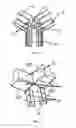
FIG. 3 illustrates assembling between the invention and a section of a cabinet frame; and
FIG. 4 illustrates assembling between a tapping hole and a bolt.
DETAILED DESCRIPTION OF THE EMBODIMENTS
As shown in FIGS. 1-4, a three-way connector for a cabinet frame comprises a body 1, multiple positioning columns 4, and 8, a pair of M6 tapping holes 7, a pair of M6 tapping holes 11, a M12 tapping hole 3, a ten-folded section 6, and a fifteen-folded section 10.
A shape of the body 1 corresponds to that of the cabinet frame.
A pair of triangular corners 2 is disposed on both sides of the body 1, whereby ensuring good appearance of the cabinet frame after welding, and matching between the cabinet frame and the fifteen-folded section.
The M12 tapping hole 3 is disposed at the top of the body 1, which makes it convenient for installation of a ring of the cabinet.
The positioning columns 4 is fit with a cavity of the ten-folded section 6, and an angle between the positioning columns 4 is 90 degrees, which ensure accurate positioning thereof.
The M6 tapping holes 7 are disposed on the positioning columns 4, and fit with an installation hole of the ten-folded section 6, whereby ensuring installation requirements for bolts, and enabling the three-way connector to be tightly connected to the section.
The positioning columns 8 are fit with a cavity of the fifteen-folded section 10, and parallel to each other, which ensure accurate positioning.
The M6 tapping holes 11 are disposed on the positioning columns 8, and fit with an installation hole of the fifteen-folded section 10, whereby ensuring installation requirements for bolts, and enabling the three-way connector to be tightly connected to the section.
An angle between the positioning columns 4 and the positioning columns 8 is 90 degrees.
The tapping hole corresponding to the frame is disposed on the body 1, the three-way connector connects sections of two types of cabinet frames altogether, and thus the sections are accurately positioned, then the cabinet frames are formed via welding, the section is connected to the three-way connector via a hexagonal nut, and the M12 tapping hole 3 disposed at the top thereof is for installation of a ring of the cabinet.
While particular embodiments of the invention have been shown and described, it will be obvious to those skilled in the art that changes and modifications may be made without departing from the invention in its broader aspects, and therefore, the aim in the appended claims is to cover all such changes and modifications as fall within the true spirit and scope of the invention.
Claims
The invention claimed is:1. A three-way connector for a cabinet frame, comprising:
a body (1);
multiple positioning columns (4, 8);
a pair of M6 tapping holes (7);
a pair of M6 tapping holes (11);
an M12 tapping hole (3);
a ten-folded section (6); and
a fifteen-folded section (10);
wherein
a pair of triangular corners (2) are disposed on both sides of said body (1);
said M12 tapping hole (3) is disposed at the top of said body (1);
said positioning columns (4) are fit with a cavity of said ten-folded section (6);
said M6 tapping holes (7) are disposed on said positioning columns (4), and are fit with an installation hole of said ten-folded section (6);
said positioning columns (8) are fit with a cavity of said fifteen-folded section (10), and are parallel to each other;
said M6 tapping holes (11) are disposed on said positioning columns (8), and are fit with an installation hole of said fifteen-folded section (10);
an angle between said positioning columns (4) is 90 degrees; and
an angle between said positioning columns (4) and said positioning columns (8) is 90 degrees.
Images & Drawings included:


Sources:
- United States Patent and Trademark Office - verify current appl. status at the USPTO↗
Recent applications in this class:
- » 20160197458 2016-07-07
Insulating support for power switchgear - » 20150333490 2015-11-19
Apparatus for enhanced merchandise display - » 20150200523 2015-07-16
Frame profile for a rack of a switchgear cabinet, and fastening clip for the frame profile - » 20150011101 2015-01-08
Single layer leadframe with integrated three-row connector - » 20140247541 2014-09-04
TELECOM CABINET DUAL TRAY SLIDER - » 20140126115 2014-05-08
Electrical junction box - » 20140063692 2014-03-06
Assembly for power connection and signal acquisition - » 20130306584 2013-11-21
Frame piece for a rack - » 20130286550 2013-10-31
Modular subsea electrical distribution system having subsea cable harness assembly and method for assembling same - » 20130213908 2013-08-22
Rack