Electronic device with remote control function
US20110057768A1
2011-03-10
12/792,679
2010-06-02
✅ Patent granted
US 8,258,922 B2
2012-09-04
-
-
Brian Zimmerman | Laura Nguyen
2031-01-13
Abstract:
A receiving module, checking module, and a controller are provided. The receiving module is configured for receiving external wireless signals. The checking module is configured for checking whether a current wireless signal comprises checking codes of a control signal which is configured for controlling the electronic device and, if yes, generating an activation signal. The controller is configured for switching the electronic device into a power-saving mode if no external wireless signal is received after a predetermined time period and switching the electronic device into a normal mode if the activation signal is received.
Inventors:
- WEN SHU 7 🇨🇳 Shenzhen City, China
- TE-HUA LEE 18 🇹🇼 Tu-Cheng, Taiwan
- CHING-CHIH LIN 2 🇹🇼 Tu-Cheng, Taiwan
- Wen Shu 4 🇨🇳 Shenzhen, China
- Ching-Chih Lin 1 🇹🇼 Taipei Hsien, Taiwan
- Te-Hua Lee 8 🇹🇼 Taipei Hsien, Taiwan
Assignee:
- HON HAI PRECISION INDUSTRY CO., LTD. 12,833 🇹🇼 Tu-Cheng, Taiwan
- HONG FU JIN PRECISION INDUSTRY (SHENZHEN) CO., LTD. 4,225 🇨🇳 Shenzhen City, China
- HON HAI PRECISION INDUSTRY CO., LTD. 2,724 🇹🇼 Tu-Cheng, New Taipei, Taiwan
- Hong Fu Jin Precision Industry (Shenzhen) Co., Ltd. 1,915 🇨🇳 Shenzhen, Guangdong Province, China
Interested in similar patents?
Get notified when new applications in this technology area are published.
Classification:
G08C17/00 » CPC main
Arrangements for transmitting signals characterised by the use of a wireless electrical link
G08C2201/10 » CPC further
Transmission systems of control signals via wireless link Power supply of remote control devices
G08B5/22 IPC
Visible signalling systems, e.g. personal calling systems, remote indication of seats occupied using electric transmission; using electromagnetic transmission
G08B1/08 IPC
Systems for signalling characterised solely by the form of transmission of the signal using electric transmission ; transformation of alarm signals to electrical signals from a different medium, e.g. transmission of an electric alarm signal upon detection of an audible alarm signal
H04Q5/22 IPC
Selecting arrangements wherein two or more subscriber stations are connected by the same line to the exchange with indirect connection, i.e. through subordinate switching centre the subordinate centre not permitting interconnection of subscribers connected thereto
H04B1/16 IPC
Details of transmission systems, not covered by a single one of groups - ; Details of transmission systems not characterised by the medium used for transmission; Receivers Circuits
Description
BACKGROUND
1. Technical Field
The present disclosure relates to electronic devices and, particularly, to an electronic device that can be controlled remotely.
2. Description of Related Art
Some electronic devices have remote control functions. To save power, such an electronic device often can work in a standby mode in which only a signal receiving module thereof is activated (thus consuming less power) for detecting incoming control signals and then all modules thereof are activated for normal working operations. However, it is not uncommon that the electronic devices can be activated by some random or unauthorized control signals, thus reducing the power efficiency of these electronic devices having this standby feature.
Therefore, it is desirable to provide an electronic device, which can overcome the above-mentioned limitations.
BRIEF DESCRIPTION OF THE DRAWINGS
Many aspects of the present electronic device should be better understood with reference to the following drawings. The components in the drawings are not necessarily drawn to scale, the emphasis instead being placed upon clearly illustrating the principles of the present electronic device. Moreover, in the drawings, like reference numerals designate corresponding parts throughout the several views.
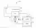
FIG. 1 is a block diagram of an electronic device, according to one embodiment.
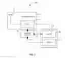
FIG. 2 is a block diagram of a checking module of the electronic device of FIG. 1.
DETAILED DESCRIPTION
Embodiments of the present electronic device will now be described in detail with reference to the drawings.
Referring to FIG. 1, an electronic device 100, according to an embodiment, can be remotely controlled by a wireless control signal. The control signal can be a radio frequency (RF) signal and includes a number of sequential codes (e.g., RF pulses). Some of the codes of the control signal function as checking codes. Thus, the electronic device 100 can check if an incoming wireless signal is an authorized control signal or not by checking the checking codes (see below). In this embodiment, the checking codes of the control signal are the first three codes of the control signal. The electronic device 100 includes a receiving module 10, a controller 20, and a checking module 30.
The receiving module 10 is configured for receiving external wireless signals. In this embodiment, the receiving module 10 includes an antenna 12 and a filter 14. The antenna 12 is configured for receiving the wireless signals. The filter 14 is configured for filtering the wireless signals to remove noise.
The controller 20 is connected to the receiving module 10 and configured for processing the control signal and controlling the electronic device 100 to perform various functions according to the control signal. The controller 20 includes a clocker 22 and a decoder 24. The clocker 22 is configured for generating timing signals and sending the generated timing signals to the checking module 30. The decoder 24 is configured for decoding the control signal and sending the decoded control signal to back-end components (not shown) of the electronic device 100 for further processing or controlling. The controller 20 can control the electronic device 100 to work in a standby mode and a normal mode. In the standby mode, the decoder 24 and the back-end components of the electronic device 100 are deactivated and thus the electronic device 100 consumes less power. In the normal mode, the decoder 24 and the back-end components of the electronic device 100 are activated for normal working operations and thus the controller 20 consumes more power. The controller 20 is programmed to switch the electronic device 100 into the standby mode if no external signal is received by the receiving module 10 after a predetermined time period. The controller 20 switches the electronic device 100 into the normal mode when an activation signal is received.
The checking module 30 includes a first terminal 31, a second terminal 32, and a third terminal 33. The first terminal 31 is connected to the receiving module 10 for receiving the wireless signals. The second terminal 32 is connected to the clocker 22 for receiving timing signals. The third terminal 33 is connected to the decoder 24. The checking module 30 is configured for checking if the check codes of a current wireless signal match predetermined values and, if yes, generates the activation signal.
The activation signal is transmitted to the decoder 24 via the third terminal 33 to activate the controller 20. It is assumed that if the first three codes of the current wireless signal are all logic high levels “111”, the current wireless signal is the control signal and the activation signal is generated.
Referring to FIG. 2, the checking module 30 includes a first circuit 34, a second circuit 35, a third circuit 36, and an adder U7. The first circuit 34 includes a first register U1. The second circuit 35 includes a second register U2 and a third register U3. The third circuit 36 includes a fourth register U4, a fifth register U5, and a sixth register U6. Each of the registers U1˜U6 includes an input terminal D, a clocking terminal C, and an output terminal Q. In this embodiment, all the registers U1˜U6 are D-type.
The input terminals D of the register U1, U2, and U4 are connected to the first terminal 31. The output terminal Q of the second register U2 is connected to the input terminal D of the third register U3. The output terminal Q of the fourth register U4 is connected to the input terminal D of the fifth register U5. The output terminal Q of the fifth register U5 is connected to the input terminal D of the sixth register U6. The clocking terminals C of the registers U1˜U6 are connected to the second terminal 32. The output terminal Q of the registers U1, U3, and U6 are connected to input ends of the adder U7. The output end of the adder U7 is connected to the third terminal 33.
Thus, the checking module 30 sequentially samples codes of the current wireless signal and only when the first three codes of the current wireless signal turn out to be three high logic levels “111”, the output end of the adder U7 (i.e., the third terminal 33) outputs a high logic level “1” as the activation signal.
The checking module 30 is not limited to this embodiment but should be changed according to the structure of the checking codes of the control signal. For example, if the checking codes of the control signal only include the first code, then the circuits 35 and 36 can be omitted. If the check codes of the control signal only include the first two codes, then the third circuit 36 can be omitted. In all, if the checking codes of the control signal include the first n codes (n is a positive integer) the checking module needs to employ n circuits, wherein the i-th circuit includes i serially connected registers (i is a positive integer and i≦n).
It will be understood that the above particular embodiments and methods are shown and described by way of illustration only. The principles and the features of the present disclosure may be employed in various and numerous embodiment thereof without departing from the scope of the disclosure as claimed. The above-described embodiments illustrate the scope of the disclosure but do not restrict the scope of the disclosure.
Claims
What is claimed is:1. An electronic device comprising:
a receiving module for receiving external wireless signals;
a checking module configured for checking if a current wireless signal comprises checking codes of a control signal which is configured for controlling the electronic device and, if yes, generating an activation signal; and
a controller configured for switching the electronic device into a power-saving mode if no external wireless signal is received after a predetermined time period and switching the electronic device into a normal mode if the activation signal is received.
2. The electronic device of claim 1, wherein the receiving module comprises an antenna and a filter; the antenna being configured for receiving the external wireless signals; the filter being configured for filtering the external wireless signals to remove noises.
3. The electronic device of claim 1, wherein the checking module comprises a first terminal, a second terminal, and a third terminal, the controller comprising a clocker for generating timing signals; the first terminal being connected to the receiving module for receiving the external wireless signals; the second terminal being connected to the clocker for receiving the timing signals; the checking module being configured for sequentially sampling codes of the current wireless signal upon receiving each of the timing signals; the third terminal being connected to the controller and configured for outputting the activation signal to the controller.
4. The electronic device of claim 3, wherein the controller comprises a decoder for decoding the control signal; the third terminal being connected to the decoder.
5. The electronic device of claim 3, wherein the checking codes of the control signal comprises first n codes; the checking module comprises n corresponding circuits and a adder, wherein n is an integer, the i-th circuit comprises i D-type registers, i is a positive integer, and i≦n; each D-type register comprising an input terminal, a clocking terminal, and an output terminal; wherein the registers of the same circuit are serially connected between the first terminal and the adder via the input terminals and the output terminals thereof, the clocking terminals are connected to the second terminal, and the adder is connected to the third terminal.
Images & Drawings included:
Sources:
- United States Patent and Trademark Office - verify current appl. status at the USPTO↗
Similar patent applications:
- » 20120025958
Electronic device with remote control function - » 20140363167
ELECTRONIC DEVICE HAVING REMOTE CONTROL FUNCTIONS - » 20090059092
Electronic device with remote control functions - » 20090153288
Handheld electronic devices with remote control functionality and gesture recognition - » 20180005517
Handheld electronic devices with remote control functionality and gesture recognition - » 20130117386
CONTROL METHOD FOR PERFORMING SOCIAL MEDIA FUNCTION BY ELECTRONIC DEVICE USING REMOTE CONTROLLER AND THE REMOTE CONTROLLER THEREOF - » 20090153289
HANDHELD ELECTRONIC DEVICES WITH BIMODAL REMOTE CONTROL FUNCTIONALITY - » 20160065828
METHOD FOR CONTROLLING ELECTRONIC DEVICE USING IP CAMERA HAVING FUNCTION OF WIRELESS REMOTE CONTROLLER - » 20140355993
ELECTRONIC DEVICE AND STORAGE MEDIUM WITH REMOTE CONTROL FUNCTION, AND REMOTE CONTROL METHOD - » 20200081599
Electronic device combining functions of touch screen and remote control and operation control method thereof
Recent applications in this class:
- » 20250292674 2025-09-18
APPARATUS, SYSTEM, AND METHOD OF MONITORING, AND RECORDING MEDIUM - » 20250218280 2025-07-03
Quantum mechanics and inspiration zone/s duplicating device - » 20250157320 2025-05-15
INTELLIGENT PROTECTION SWITCH SYSTEM AND ITS APPLIED MOLDED CASE CIRCUIT BREAKERS AND SOCKETS - » 20240257634 2024-08-01
APPARATUS, SYSTEM, AND METHOD OF MONITORING, AND RECORDING MEDIUM - » 20240257633 2024-08-01
CONTROL DEVICE, CONTROL METHOD, AND CONTROL PROGRAM - » 20240233517 2024-07-11
Automated Programming of a Remote Control - » 20240135802 2024-04-25
Automated programming of a remote control - » 20230326330 2023-10-12
COMMUNICATION SYSTEM IN WHICH REMOTE CONTROL IS PERFORMED FROM TERMINAL APPARATUS, SERVER APPARATUS, CONTROL METHOD THEREFOR, AND STORAGE MEDIUM - » 20230186757 2023-06-15
Apparatus, system, and method of monitoring, and recording medium - » 20230028355 2023-01-26
CONTROLLING OUTPUT OF ELECTRONIC LABELS FROM A CAMERA
Recent applications for this Assignee:
- » 20140233961 2014-08-21
Optical communication module including optical-electrical signal converters and optical signal generators - » 20140083669 2014-03-27
HEAT SINK - » 20140083669 2014-03-27
HEAT SINK - » 20140063746 2014-03-06
Electronic device with heat dissipation assembly - » 20140061224 2014-03-06
AUTOMATIC VENDING MACHINE - » 20140060914 2014-03-06
Enclosure with shield apparatus - » 20140058727 2014-02-27
MULTIMEDIA RECORDING SYSTEM AND METHOD - » 20140055955 2014-02-27
Fastener - » 20140055322 2014-02-27
DISPLAY SYSTEM AND HEAD-MOUNTED DISPLAY APPARATUS - » 20140054439 2014-02-27
CONTAINER DATA CENTER WITH SUPPORTING APPARATUS