Personal water safety device
US20110068933A1
2011-03-24
12/650,573
2009-12-31
✅ Patent granted
US 8,248,251 B2
2012-08-21
-
-
Daniel Wu | Emily C Terrell
2030-12-04
Abstract:
A personal water safety device includes a barrel portion, and a base part. The base part connects two portions of a swimming goggle frame. The barrel portion includes a button, and a cylinder connected to the button via a spring. The base part includes a timer connected to the cylinder, and an alarm electrically connected to the timer. Water enters the cylinder when the button is pressed, and the timer measures an elapsed time when electrical conductivity of interior of the cylinder is in a predetermined range. The alarm generates an alarm when the measured time exceeds a predetermined time limit.
Inventors:
- CHIEN-LIN CHEN 14 🇹🇼 Tu-Cheng, Taiwan
- PI-JYE TSAUR 10 🇹🇼 Tu-Cheng, Taiwan
- Chien-Lin Chen 5 🇹🇼 Taipei Hsien, Taiwan
- Pi-Jye Tsaur 6 🇹🇼 Taipei Hsien, Taiwan
Assignee:
- HON HAI PRECISION INDUSTRY CO., LTD. 12,833 🇹🇼 Tu-Cheng, Taiwan
- HON HAI PRECISION INDUSTRY CO., LTD. 2,724 🇹🇼 Tu-Cheng, New Taipei, Taiwan
Interested in similar patents?
Get notified when new applications in this technology area are published.
Classification:
G08B23/00 IPC
Alarms responsive to unspecified undesired or abnormal conditions
G08B21/088 » CPC main
Alarms responsive to a single specified undesired or abnormal condition and not otherwise provided for; Alarms for ensuring the safety of persons responsive to the presence of persons in a body of water, e.g. a swimming pool; responsive to an abnormal condition of a body of water by monitoring a device worn by the person, e.g. a bracelet attached to the swimmer
A63B33/002 » CPC further
Swimming equipment attachable to the head, e.g. swim caps or goggles Swimming goggles
A63B2220/80 » CPC further
Measuring of physical parameters relating to sporting activity Special sensors, transducers or devices therefor
A63B2220/833 » CPC further
Measuring of physical parameters relating to sporting activity; Special sensors, transducers or devices therefor characterised by the position of the sensor Sensors arranged on the exercise apparatus or sports implement
G01S3/80 IPC
Direction-finders for determining the direction from which infrasonic, sonic, ultrasonic, or electromagnetic waves, or particle emission, not having a directional significance, are being received using ultrasonic, sonic or infrasonic waves
G08B21/00 IPC
Alarms responsive to a single specified undesired or abnormal condition and not otherwise provided for
Description
BACKGROUND
1. Technical Field
Embodiments of the present disclosure generally relate to safety devices, and more particularly to a personal water safety device.
2. Description of Related Art
Currently, if a swimmer is submerged for too long, there is no way for people nearby to know this unless they are watching at the time.
Therefore, there is room for improvement within the art.
BRIEF DESCRIPTION OF THE DRAWINGS
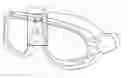
FIG. 1 is a schematic diagram of a pair of swimming goggles including a safety device.
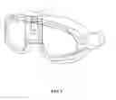
FIG. 2 is an enlarged view of the safety device of FIG. 1.
FIG. 3 is a block diagram of an exemplary embodiment of the safety device of FIG. 1.
FIG. 4 is an isometric view of a cylinder of FIG. 3 with water in it.
DETAILED DESCRIPTION
The disclosure is illustrated by way of example and not by way of limitation in the figures of the accompanying drawings in which like references indicate similar elements. It should be noted that references to “an” or “one” embodiment in this disclosure are not necessarily to the same embodiment, and such references mean at least one.
FIG. 1 is a schematic diagram of a pair of swimming goggles including a safety device 1. In the exemplary embodiment, the safety device 1 is between two portions of the goggle frame. The safety device 1 acts as an alarm should a swimmer wearing it have trouble in the water. The safety device 1 is installed in the goggles as an example for the embodiment and may be installed elsewhere about the swimmer in other embodiments, such as in other articles of swimwear or swim equipment.
FIG. 2 is an enlarged view of the safety device 1. The safety device 1 typically includes a barrel portion 10, and a base part 12 connected to the barrel portion 10. In the embodiment, the barrel portion 10 may be a cylinder. The barrel portion 10 includes a button 100, and a cylinder 200 connected to the button 100 via a spring 105 (see in FIG. 4). The button 100 protrudes out a head portion of the barrel portion 10, and the button 100 is narrower than the barrel portion 10. The base part 12 has a cutout in a bottom surface 124 thereof to accommodate a bridge of the nose of a swimmer. In the embodiment, an upper end of the base part 12 is narrower than a bottom end of the base part 12. The base part 12 further includes one or more holes 120 (two holes are shown in FIG. 2 and FIG. 4) that are connected to the cylinder 200 via one or more pipes 205 (see in FIG. 4).
FIG. 3 is a block diagram of an exemplary embodiment of the safety device 1. The safety device 1 further includes an amplifier 300, a timer 400, and an alarm 500, which are installed in the base part 12. The amplifier 300 is connected to the timer 400. The timer 400 is connected to the cylinder 200 and the button 100. The alarm 500 is electrically connected to the timer 400.
In the embodiment, the cylinder 200 is a conducting cylinder that can detect the electrical conductivity of the interior of the cylinder 200, and determine when water has filled the barrel portion 10 thus recognizing whether the safety device 1 (namely the swimmer) is under water. To accurately measure what may be a relatively small difference in the electrical conductivity of the cylinder 200 be it with air or water, the amplifier 300 is capable of amplifying the measured electrical conductivity. When the electrical conductivity is within a predetermined range the timer 400 is activated.
If water pressure activates the button 100 or if it is manually pressed by a swimmer, water can enter the cylinder 200 under ambient pressure through inlets exposed when the button 100 is depressed. As illustrated in FIG. 4, the inlets are gaps between the button 100 and the barrel portion 10. The timer 400 measures an elapsed time when electrical conductivity of the interior of the cylinder 200 is in the predetermined range. Timing stops if the electrical conductivity moves back out of the predetermined range, for example, the timing stops when the safety device 1 is out of water. If the measured time exceeds a predetermined time limit (e.g., 30 seconds), the alarm 500 generates an alarm (such as a piercing whistle) to alert anyone in the vicinity of an emergency. In the embodiment, the time limit can be set by the swimmer Note, the alarm 500 can be configured to include any alarm apparatus that can be seen or heard above the water even though the alarm 500 is submerged. For example, flashing light may be used, or some dye expelled by the alarm 500. In other embodiments, the alarm 500 may use wireless technology such as BLUETOOTH to communicate with a device left above water that can be more easily seen or heard.
In another embodiment, the cylinder 200 includes one or more outlets (not shown) that are connected to the holes 120 via the one or more pipes 205. If the safety device 1 is out of the water, any water in the cylinder 200 drains out through the one or more pipes 205.
Although certain inventive embodiments of the present disclosure have been specifically described, the present disclosure is not to be construed as being limited thereto. Various changes or modifications may be made to the present disclosure without departing from the scope and spirit of the present disclosure.
Claims
What is claimed is:1. A personal water safety device, comprising:
a barrel portion, comprising:
a button installed in the barrel portion comprising a head portion, the button protruding out of the head portion; and
a cylinder connected to the button, the cylinder formed such that water enters the cylinder in response to the button being pressed; and
a base part connected to the barrel portion, the base part comprising:
a timer connected to the cylinder, to measure an elapsed time when electrical conductivity of interior of the cylinder is in a predetermined range; and
an alarm electrically connected to the timer, to generate an alarm upon a condition that the measured time exceeds a predetermined time limit.
2. The safety device as claimed in claim 1, wherein the cylinder is a conducting cylinder that recognizes whether the safety device is under water by detecting the electrical conductivity of the interior of the cylinder.
3. The safety device as claimed in claim 2, further comprising an amplifier that amplifies the measured electrical conductivity of the interior of the cylinder.
4. The safety device as claimed in claim 1, wherein either the barrel portion or the button is a cylinder.
5. The safety device as claimed in claim 4, wherein the button is narrower than the barrel portion, water enters the cylinder through a gap between the button and the barrel portion.
6. A personal water safety device, comprising:
a barrel portion, comprising:
a button installed in the barrel portion comprising a head portion, the button protruding out of the head portion; and
a cylinder connected to the button, the cylinder formed such that water enters the cylinder in response to the button being pressed; and
a base part connecting two portions of a swimming goggle frame, the base part comprising:
a timer connected to the cylinder, to measure an elapsed time when electrical conductivity of interior of the cylinder is in a predetermined range; and
an alarm electrically connected to the timer, to generate an alarm upon a condition that the measured time exceeds a predetermined time limit.
7. The safety device as claimed in claim 6, wherein the cylinder is a conducting cylinder that recognizes whether the safety device is under water by detecting the electrical conductivity of the interior of the cylinder.
8. The safety device as claimed in claim 7, further comprising an amplifier that amplifies the measured electrical conductivity of the interior of the cylinder.
9. The safety device as claimed in claim 6, wherein either the barrel portion or the button is a cylinder.
10. The safety device as claimed in claim 9, wherein the button is narrower than the barrel portion, water enters the cylinder through a gap between the button and the barrel portion.
11. The safety device as claimed in claim 6, wherein the base part comprises a cutout in a bottom surface thereof to accommodate a bridge of the nose of a swimmer.
Images & Drawings included:


Sources:
- United States Patent and Trademark Office - verify current appl. status at the USPTO↗
Similar patent applications:
- » 20090130933
Personal water safety device - » 20110074586
Personal water safety device and method thereof - » 20110090763
Personal water safety device and method thereof - » 20120034831
PERSONAL WATER SAFETY DEVICE
Recent applications in this class:
- » 20240233508 2024-07-11
DROWING PREVENTION SYSTEM - » 20240105043 2024-03-28
WEARABLE DEVICE USED AS DIGITAL POOL ATTENDANT - » 20240087440 2024-03-14
IoT based management system and a method for assisting users around a swimming pool - » 20240078888 2024-03-07
Overboard fall detection unit, portable terminal, and server device - » 20230011440 2023-01-12
Signal Device for Maritime Distress Rescue and Surveilance Device for Maritime Distress Rescue - » 20220309897 2022-09-29
Wearable Safety Device for Swimming - » 20220246017 2022-08-04
System and a method for surveilling swimmers - » 20220215736 2022-07-07
Apparatus for detection of drowning conditions - » 20220044541 2022-02-10
ALARM ARRANGEMENT - » 20220036717 2022-02-03
Drowning prevention and soothing device
Recent applications for this Assignee:
- » 20140233961 2014-08-21
Optical communication module including optical-electrical signal converters and optical signal generators - » 20140083669 2014-03-27
HEAT SINK - » 20140063746 2014-03-06
Electronic device with heat dissipation assembly - » 20140061224 2014-03-06
AUTOMATIC VENDING MACHINE - » 20140060914 2014-03-06
Enclosure with shield apparatus - » 20140058727 2014-02-27
MULTIMEDIA RECORDING SYSTEM AND METHOD - » 20140055955 2014-02-27
Fastener - » 20140055322 2014-02-27
DISPLAY SYSTEM AND HEAD-MOUNTED DISPLAY APPARATUS - » 20140054439 2014-02-27
CONTAINER DATA CENTER WITH SUPPORTING APPARATUS - » 20140054311 2014-02-27
AUTOMATIC VENDING MACHINE WITH MOVING MEMBER FOR PRODUCTS