Laser welder
US20110089148A1
2011-04-21
12/907,151
2010-10-19
✅ Patent granted
US 8,420,976 B2
2013-04-16
-
-
Sang Paik
Andrew Wilford
2031-12-06
Abstract:
An apparatus for fitting two first workpieces with respective second workpieces of different dimensions has a track extending longitudinally through an assembly station and a welding station. An assembling appliance in the assembly station has a pair of jigs each dimensioned to fit with a respective one of the second workpieces, and a holdown appliance in the welding station similarly has a pair of differently sized holddowns. The holddown appliance can move between a pair of positions in each of which a respective one of the holddowns is aligned under the welding head. A workpiece holder in which either of the first workpieces can be held is shiftable between positions in the assembly station under the assembling appliances and a position in the welding station underneath a stationary welding head therein.
Assignee:
- EMAG HOLDING GMBH 33 🇩🇪 Salach, Germany
Applicant:
Interested in similar patents?
Get notified when new applications in this technology area are published.
Classification:
B23K26/0838 » CPC main
Working by laser beam, e.g. welding, cutting or boring; Devices involving relative movement between laser beam and workpiece; Devices involving movement of the workpiece in at least one axial direction by using an endless conveyor belt
B23K26/702 » CPC further
Working by laser beam, e.g. welding, cutting or boring; Auxiliary operations or equipment Auxiliary equipment
B23K37/047 » CPC further
Auxiliary devices or processes, not specially adapted to a procedure covered by only one of the preceding main groups for holding or positioning work moving work to adjust its position between soldering, welding or cutting steps
B23K26/20 IPC
Working by laser beam, e.g. welding, cutting or boring Bonding
B23K26/00 IPC
Working by laser beam, e.g. welding, cutting or boring
B23K37/00 IPC
Auxiliary devices or processes, not specially adapted to a procedure covered by only one of the preceding main groups
Description
FIELD OF THE INVENTION
The present invention relates to laser welder. More particularly this invention concerns an apparatus for fitting together and then welding together two workpieces.
BACKGROUND OF THE INVENTION
The standard procedure for making a multipart workpiece, for instance a wheel hub, is to first fit a base or first workpiece with a second workpiece. For instance a cylindrical base workpiece can be fitted with a ring. To this end the base workpiece is mounted in a holder and the ring is fitted to a jig. The holder presses the base workpiece up against the ring to fit them together, then the fitted-together parts are shifted to a welding station where they are rotated under a welding head that joins them along a circular seam.
Such an apparatus is described in DE 199 47 588 A1. Specified as different laser machining processes are material removal, material deposition, hardening and welding. The holding device can be moved under digital control in at least two axis running transverse to one another and, by means of a pressing process, can bring two workpieces into a defined position relative to one another for laser welding. The holding device is configured as a workpiece spindle rotatable about an axis. Further, a laser beam head is provided which can be pivoted about two axes. For joining a flange shaft and a bell-shaped workpiece, a chuck adapted to the workpiece geometry and an annular holddown or jig are provided in the holding means.
While this system works well, whenever workpiece size changes, it is necessary to shut down the entire machine and change the holddowns and jigs. This can represent a significant loss of production.
OBJECT OF THE INVENTION
It is the object of the present invention to provide a flexible laser welder to optimize use with workpieces of different dimensions.
SUMMARY OF THE INVENTION
These objects are attained in an apparatus for fitting two first workpieces with respective second workpieces of different dimensions. The apparatus has a track extending longitudinally through an assembly station and a welding station, a stationary laser-welding head in the welding station, an assembling appliance in the assembly station having a pair of jigs each dimensioned to fit with a respective one of the second workpieces, and a holddown appliance in the welding station having a pair of holddowns each dimensioned to fit with a respective one of the second workpieces. This holddown appliance is shiftable between a pair of positions in each of which a respective one of the holddowns is aligned under the welding head. A workpiece holder in which either of the first workpieces can be held is shiftable between positions in the assembly station under the assembling appliances and a position in the welding station underneath the welding head. The holder is also movable for pressing the first workpiece it is holding against and fitting it with one of the second workpieces in the respective jig and for thereafter moving the fitted together first and second workpieces into position under the welding head and moving them to weld them together along a seam.
An advantageous aspect of the invention is to have the appropriate assembling means available in the assembling position for machining different workpieces and also to provide a holddown adapted to the workpiece geometry in the welding station. Thereby, retrofitting of the machine can be automated. Moreover, changeover times between workpieces of different dimensions are significantly reduced. Because the workpiece holder moves the workpiece to the respective position, the operating personnel does no longer need to intervene. In an advantageous embodiment, the holddowns necessary for fixing the components are arranged in a magazine. If a holddown needs to be changed in the welding station, the magazine is moved on guide rails thereby positioning the desired holddown. In a further advantageous embodiment, the moveable workpiece holder can be coupled to the magazine. Thereby, the magazine does not need its own drive.
BRIEF DESCRIPTION OF THE DRAWING
The above and other objects, features, and advantages will become more readily apparent from the following description, reference being made to the accompanying drawing in which:
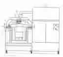
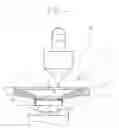
FIG. 1 shows the laser welder in a front view;
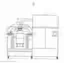
FIG. 2 shows the laser welder in a side view;
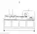
FIG. 3 shows the laser welder according to FIG. 2 when machining of a large workpiece; and
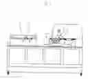
FIG. 4 shows the welding station in an enlarged view.
SPECIFIC DESCRIPTION
As seen in FIG. 1, a base frame 1 has two longitudinally extending and vertical walls 2 and 2′ spaced transversely from each other. Horizontal and longitudinally extending inner guide rails 3′ for a slide 4 sit atop the walls 2 and 2′. An actuator shown schematically at 19 can shift the slide 4 longitudinally. The slide 4 is provided with a workpiece holder 5 configured as a spindle vertically shiftable on guides 6 below the rails 3′. The motor spindle extends along and is centered on a vertical axis A and carries at its upper end a chuck 7 that holds a first workpiece 8. Above the slide 4, a downwardly U-shaped magazine 9 carries longitudinally spaced identical holddowns 10 and 10′. The magazine 9 can be moved on outer guide rails 3 also in the longitudinal and horizontal direction. The slide 4 can be connected via a coupling 11 to the magazine 9 and can push it into the desired position. Thus, the magazine 9 does not need its own drive. A laser source or generator 12 is provided on the right side in FIG. 1. A downwardly directed laser head 13 connected to it is stationary.
In the embodiment shown in FIG. 2, a laser welder for workpieces with two different diameters is illustrated in side view. The welder can be used for machining of workpieces of different shapes and/or dimensions. A small first or base workpiece 8 is fitted to the chuck 7, and the slide 4 transports it into an assembly station 14′. There, the workpiece holder 5 moves upward and presses the workpiece 8 and a second workpiece or part 17 against a jig 15′ which corresponds to the workpiece dimensions. This action fits the part 17 down against the workpiece 8. After this, the workpiece holder 5 is lowered again and the slide 4 moves to a welding station 16. There, the workpiece holder 5 is moved upward and presses the workpieces 8 and 17 against the holddown 10′. The motor spindle then rotates the workpiece 8 underneath the laser head 13, and a weld seam 18 is created joining the workpieces 8 and 17 together.
Like FIG. 2, FIG. 3 shows the machining of a first workpiece 8′ with a larger diameter. For this purpose, the magazine 9, which has been connected to the slide 4 via the coupling 11, has been moved so the holddown 10 is in the welding station 16. Prior to this the workpiece holder 5 has pressed the bigger workpiece 8′ up against the jig 15 to fit it with a larger second workpiece.
For clarification purposes, FIG. 4 shows the welding station in an enlarged view. The part 17, which had previously been pressed in the assembly station 14′ onto the workpiece 8 held in the chuck 7, is in the welding station 16. The motor spindle moves upward and pushes the workpiece 8 against the holddown 10. By exposure to laser radiation from the laser head 13, the weld seam 18 is formed.
Thus, with this laser welder, automated retrofitting without moving the laser head is possible.
Claims
I claim:1. An apparatus for fitting two first workpieces with respective second workpieces of different dimensions, the apparatus comprising:
a track extending longitudinally through an assembly station and a welding station;
a stationary laser-welding head in the welding station;
an assembling appliance in the assembly station having a pair of jigs each dimensioned to fit with a respective one of the second workpieces;
a holddown appliance in the welding station having a pair of holddowns each dimensioned to fit with a respective one of the second workpieces, the holddown appliance being shiftable between a pair of positions in each of which a respective one of the holddowns is aligned under the welding head;
a workpiece holder in which either of the first workpieces can be held; and
actuator means for shifting the holder between positions in the assembly station under the assembling appliance and a position in the welding station underneath the welding head, the holder being shiftable for pressing the first workpiece it is holding against and assembling it with one of the second workpieces in the respective jig and for thereafter moving the fitted together first and second workpieces into position under the welding head and moving them against one of the holddowns while welding them together along a seam.
2. The laser-welding apparatus defined in claim 1 wherein the holder is shiftable along the track.
3. The laser-welding apparatus defined in claim 2 wherein the holddown appliance is a carriage shiftable along the track.
4. The laser-welding apparatus defined in claim 2, further comprising
a coupling engageable between the holddown appliance and the holder for joint displacement with the holder.
5. The laser-welding apparatus defined in claim 2 wherein the track includes at least one pair of horizontal and longitudinally extending rails extending through the stations.
6. The laser-welding apparatus defined in claim 3 wherein the holder is vertically displaceable.
7. The laser-welding apparatus defined in claim 6 wherein the holder is movable underneath the assembly appliance.
8. The laser-welding apparatus defined in claim 6 wherein the workpiece is movable underneath the holddown appliance.
9. The laser-welding apparatus defined in claim 6 wherein the holder can rotate the workpiece about a vertical axis.
Images & Drawings included:
Sources:
- United States Patent and Trademark Office - verify current appl. status at the USPTO↗
Similar patent applications:
- » 10059634
Apparatus and method for closed-loop control of laser welder for welding polymeric catheter components - » 11057337
Hand-held laser welder remote control console - » 20060000812
Method and apparatus for controlling and adjusting the intensity profile of a laser beam employed in a laser welder for welding polymeric and metallic components - » 20120234804
Spatter removing device for laser welder - » 20140183173
LASER WELDER - » 20170028506
Laser welder alignment system - » 20200055150
ULTRA HIGH VACUUM LASER WELDER SYSTEM - » 20240367260
SYSTEMS AND METHODS FOR LASER CONTROL OF A LASER WELDER AND OPERATIONAL SETTINGS
Recent applications in this class:
- » 20240424605 2024-12-26
APPARATUS FOR CUTTING A SHEET OF AEROSOL-GENERATING MATERIAL - » 20240383071 2024-11-21
Method and Device for Laser Welding of Plate-Shaped Workpieces - » 20240375215 2024-11-14
Method for Laser Welding of Steel Plates - » 20240335906 2024-10-10
LASER BLANKING DEVICE - » 20240238898 2024-07-18
DEVICE AND METHOD FOR PRODUCING AN ELECTRODE - » 20230398631 2023-12-14
LASER CUTTING SELF-WRAPPING, SPLIT SLEEVES FROM CONTINUOUS FEED - » 20230249286 2023-08-10
APPARATUS FOR MANUFACTURING DISPLAY DEVICE AND METHOD OF MANUFACTURING DISPLAY DEVICE - » 20210379696 2021-12-09
Laser processing machine and control method therefor - » 20210268603 2021-09-02
Laser processing apparatus - » 20200338667 2020-10-29
Support device with slats mounted on a basic components, for storing or transporting single sheets or stacks of a packaging material
Recent applications for this Assignee:
- » 20160346894 2016-12-01
Dual-spindle grinding machine - » 20160278169 2016-09-22
Inductive hardening machine - » 20160023316 2016-01-28
Dual-spindle machining apparatus - » 20150018179 2015-01-15
Method and apparatus for changing tools - » 20140326114 2014-11-06
Double-spindle machining apparatus - » 20140157559 2014-06-12
Machining apparatus - » 20140094097 2014-04-03
Dual-spindle grinder - » 20140079500 2014-03-20
Machining apparatus with chip shield - » 20140030969 2014-01-30
Grinding disk and apparatus - » 20130340242 2013-12-26
Method and apparatus for complete machining of a shaft-shaped workpiece