Longitudinal link for an auxiliary frame, particularly for motor vehicles
US20110163513A1
2011-07-07
12/932,899
2011-03-09
✅ Patent granted
US 8,393,627 B2
2013-03-12
-
-
Joseph Rocca
Collard & Roe, P.C.
2031-03-09
Abstract:
The invention relates to an auxiliary frame (1) for multi-link rear axles of motor vehicles, comprising two lateral auxiliary frame parts (B) which are embodied at least approximately in a V-shaped manner in such an arrangement that the vertexes (6, 7) thereof face each other and are joined to each other via a central auxiliary frame part (C) that extends perpendicular to the longitudinal axis of the vehicle. The lateral auxiliary frame parts and the central auxiliary frame part are configured as hollow profiled members while the lateral auxiliary frame parts are provided with at least three of the following receptacles or recesses: the top transverse link; the bottom transverse link; the stabilizer; the longitudinal links; the fixture of the auxiliary frame to the vehicle body.
Assignee:
- KSM CASTINGS GMBH 17 🇩🇪 Hildesheim, Germany
- KSM CASTINGS GROUP GMBH 48 🇩🇪 Hildesheim, Germany
- IAMT INGENIEURGESELLSCHAFT FUR ALLGEMEINE MASCHINENTECHNIK MBH 2 🇩🇪 Plauen, Germany
Applicant:
Interested in similar patents?
Get notified when new applications in this technology area are published.
Classification:
B60G3/202 » CPC main
Resilient suspensions for a single wheel with two or more pivoted arms, e.g. parallelogram all arms being rigid having one longitudinal arm and two parallel transversal arms, e.g. dual-link type strut suspension
B60G3/22 » CPC further
Resilient suspensions for a single wheel with two or more pivoted arms, e.g. parallelogram all arms being rigid a rigid arm forming the axle housing
B60G7/001 » CPC further
Pivoted suspension arms; Accessories thereof Suspension arms, e.g. constructional features
B60G2206/50 » CPC further
Indexing codes related to the manufacturing of suspensions: constructional features, the materials used, procedures or tools; Constructional features of suspension elements, e.g. arms, dampers, springs Constructional features of wheel supports or knuckles, e.g. steering knuckles, spindle attachments
B60G2206/60 » CPC further
Indexing codes related to the manufacturing of suspensions: constructional features, the materials used, procedures or tools; Constructional features of suspension elements, e.g. arms, dampers, springs Subframe construction
B60G2206/7102 » CPC further
Indexing codes related to the manufacturing of suspensions: constructional features, the materials used, procedures or tools; Constructional features of suspension elements, e.g. arms, dampers, springs; Materials used in suspensions; Light weight materials Aluminium alloys
B60G2206/8101 » CPC further
Indexing codes related to the manufacturing of suspensions: constructional features, the materials used, procedures or tools; Constructional features of suspension elements, e.g. arms, dampers, springs; Manufacturing procedures; Shaping by casting
B62D21/11 » CPC further
Understructures, i.e. chassis frame on which a vehicle body may be mounted with resilient means for suspension, e.g. of wheels or engine; sub-frames for mounting engine or suspensions
B60G3/12 IPC
Resilient suspensions for a single wheel with a single pivoted arm the arm being essentially parallel to the longitudinal axis of the vehicle
B60G3/14 IPC
Resilient suspensions for a single wheel with a single pivoted arm the arm being essentially parallel to the longitudinal axis of the vehicle the arm being rigid
B60G21/055 IPC
Interconnection systems for two or more resiliently-suspended wheels, e.g. for stabilising a vehicle body with respect to acceleration, deceleration or centrifugal forces permanently interconnected mechanically between wheels on the same axle but on different sides of the vehicle, i.e. the left and right wheel suspensions being interconnected Stabiliser bars
Description
CROSS REFERENCE TO RELATED APPLICATIONS
This application is a divisional of and Applicants claim priority under 35 U.S.C. §§120 and 121 on U.S. application Ser. No. 10/990,312 filed on Feb. 11, 2008, which application is a national stage application under 35 U.S.C. §371 of PCT Application No. PCT/DE2006/001581 filed Sep. 8, 2006 which claims priority under 35 U.S.C. §119 from German Patent Application No. 10 2005 043 764.8 filed Sep. 13, 2005, the disclosures of each of which are hereby incorporated by reference.
BACKGROUND OF THE INVENTION
Field of the Invention
The invention relates to an auxiliary frame, more preferably a rear axle auxiliary frame for motor vehicles with multi-link rear axles.
Such multi-link rear axles in themselves offer optimal possibilities for deliberately influencing the wheel control and the driving characteristics in a wide range of driving situations. Here, the links and also other elements of a vehicle are generally preassembled into a unit on an auxiliary frame, also described as bogie or axle support and these fastened to body regions or the chassis.
However, the rear axles known to date embodied in this way frequently have the disadvantage of very high manufacturing effort and are consequently cost-intensive.
SUMMARY OF THE INVENTION
The present invention was based on the object of manufacturing such rear axles, faster, simpler and thus more cost-effectively and to expand the possible applications, which because of the higher quantities involved, in turn results in lower-priced products.
In addition, costs are to be further reduced, accuracy increased and quality improved through the use of advanced and cost-effective casting technologies as well as optimal materials.
According to the invention this is achieved in that an auxiliary frame, more preferably a rear axle auxiliary frame, is equipped in such a manner that it consists of two lateral auxiliary frame parts which are embodied at least approximately in a V-shaped manner in such an arrangement that the vertexes thereof face each other and are joined to each other via a central auxiliary frame part that extends perpendicular to the longitudinal axis of the vehicle, the lateral auxiliary frame parts and the central auxiliary frame part are configured as hollow profiled members and the lateral auxiliary frame parts comprise at least three of the following receptacles or recesses for
-
- the top transverse links
- the bottom transverse links
- the stabilizer
- the longitudinal links
- the fixture of the auxiliary frame to the vehicle body.
This can be particularly advantageous if the V-shaped lateral auxiliary frame parts comprise a U-shaped cross section with reinforcement ribs running between the legs.
The V-shaped lateral parts in their vertex region can have the foot of a Y moulded on with a cross section corresponding to the central auxiliary frame part, wherein the central auxiliary frame part can be accommodated in the vertex regions or the foot region of the Y. A square hollow profiled member, which can be an extruded profile, can be suitable as profile for the central auxiliary frame part in a particularly advantageous manner.
When using central auxiliary frame parts of different lengths, vehicles with different track width can be equipped with uniform lateral auxiliary frame parts which, because of the quantities employed, substantially favors economical manufacture.
It is furthermore advantageous if the lateral auxiliary frame parts and/or the central auxiliary frame part consist of light metal, wherein Al-alloys are particularly suitable. Here, the lateral auxiliary frame parts can be die-castings and the central auxiliary frame part, as already mentioned, an extruded profile. Such parts can be connected with each other also in a relatively simple manner through welding.
The recesses for the fastening of the auxiliary frame to the body or for passing-through of fastening elements in this case are each practically provided at the end of the legs of the lateral auxiliary frame parts.
A further inventive idea relates to a particular embodiment of a longitudinal link which can be used both in connection with an auxiliary frame of the kind described as well as with rear axles embodied in a different manner. Said longitudinal link is characterized in that said longitudinal link in its region between an articulation point on the auxiliary frame and its wheel support region moulded onto its other end as one piece is a hollow profiled member. Here, the hollow profiled member can be a closed profile for example a round profile, which preferentially consists of light metal, for example of an Al-alloy.
It is particularly advantageous with regard to the achievement of great stiffness if the longitudinal link in its region between fastening point on the auxiliary frame and its wheel support region additionally contains a hollow body, while it can be advantageous with regard to the achievement of light-weight construction, if the longitudinal link is an Al-chill casting, in which the additional hollow body is cast-in.
BRIEF DESCRIPTION OF THE DRAWINGS
The invention is explained in more detail by means of the FIGS. 1 to 7.
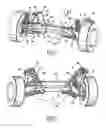
Here, FIG. 1 shows a rear axle with an auxiliary frame 1 and axle elements fastened thereto on the example of a non-powered rear axle.
FIG. 2 shows a view from FIG. 1 swiveled about the axes XYZ,
FIG. 3 the auxiliary frame 1 from a perspective corresponding to FIG. 2,
FIG. 4 a view of the auxiliary frame 1 from a similar view as FIG. 1.
FIGS. 5 to 7 show a special longitudinal link according to a further inventive idea, wherein
FIG. 5 shows the longitudinal link in the installed state,
FIG. 6 one such in view and
FIG. 7 one such in the cut state.
DETAILED DESCRIPTION OF THE PREFERRED EMBODIMENTS
The auxiliary frame 1, with view of FIG. 1 and in the driving direction F, consists of a left lateral auxiliary frame part A and a right lateral auxiliary frame part B. Each of the lateral parts is embodied in at least an approximately V-shaped manner with legs 2, 3 as well as 4, 5. The two legs each meet in their vertex region 6, 7 and additionally have a foot shoulder 8, 9 and thus altogether an at least approximately Y-shaped embodiment. The foot shoulders face in the direction of the vehicle longitudinal axis, i.e. towards each other and have the profiling of a rectangle 10, 11 in which the central auxiliary frame part C is accommodated and welded together with the profiles 8, 9.
At the ends of the V-shaped legs the fastening points or the receptacles for the passing-through of fastening means for the articulation of the auxiliary frame to the body or the chassis of the vehicle are provided, specifically the left lateral auxiliary frame part A has a fastening point 12, a rear fastening point 13 and the right lateral auxiliary frame part B a front fastening point 14 and a rear fastening point 15. In addition, the auxiliary frame has receptacle points for the fastening of parts of the rear axle which for the sake of simplification are provided with the same reference symbols each for the right and the left lateral part and in part are also shown only once, since it practically concerns mirror-image arrangements.
The longitudinal link 17 is articulated on the fastening point 16, the top and bottom transverse links 18, 19 are articulated on the fastening points 20, 21.
For the stabilizer 22, as is more preferably evident in connection with FIGS. 2 and 3, fastening points 23 are provided on the bottom region of the lateral auxiliary frame parts.
As is more preferably evident in connection with FIGS. 2 and 3 the lateral auxiliary frame parts have a U-shaped cross section with reinforcement ribs 24, 25 and 26, 27 which at least substantially run between the U-shaped legs of the lateral parts. In a particularly favorable manner the lateral auxiliary frame parts A, B can consists of aluminum die-casting while the central auxiliary frame part C is practically a rectangular hollow profiled member that can be manufactured as aluminum extruded profile.
By varying the length of the central auxiliary frame part C rear axles with different track width can be created in a particularly economical manner.
To realize an economical rear axle more preferably, however not exclusively, in connection with the present invention a longitudinal link 17 according to FIGS. 5, 6 and 7 can also be suitable according to a further inventive idea, which longitudinal link with its eye 30 can be articulated on the fastening point 16 and which, on its opposite end, has the wheel support region 31 moulded on as one piece. The region 32 serves for the articulation of the top transverse link 18 and the articulation point 33 for the articulation of the stabilizer 22. In a receptacle opening 34 a steel axle pin 35 for receiving the wheel bearing is provided. A fastening point 36 serves for the articulation of the transverse link 19.
The longitudinal link 17 with its wheel support region 31 moulded on as one piece can be manufactured in a particularly favorable manner as an aluminum chill casting, which, in its region 17a located between the fastenings points 30 and 34, contains an aluminum tube that is cast in. As a result, the corresponding longitudinal link is embodied as hollow profiled member for great stiffness with low mass and low costs at the same time.
Claims
What is claimed is:1. A longitudinal link for an auxiliary frame, wherein the longitudinal link in its region between an articulation point for fastening on the auxiliary frame and its wheel support region moulded onto the other end as one piece is a hollow profiled member.
2. The longitudinal link according to claim 1, wherein the hollow profiled member is a closed profile.
3. The longitudinal link according to claim 1, wherein the longitudinal link in its region between fastening point on the auxiliary frame and its wheel support region additionally contains a hollow body.
4. The longitudinal link according to claim 1, wherein the longitudinal link is an aluminum chill casting.
5. The longitudinal link according to claim 3, wherein the additional hollow body is cast in the longitudinal link.
6. The longitudinal link according to claim 5, wherein the hollow body is an Al-hollow body.
7. The longitudinal link according to claim 1, wherein the longitudinal link is connectable with an auxiliary frame, especially a rear axle auxiliary frame for multi-link rear axles of motor vehicles, whereby the auxiliary frame consists of two lateral auxiliary frame parts which at least approximately are embodied in a V-shaped manner in such an arrangement that the vertexes thereof face each other and are joined to each other via a central auxiliary frame part that extends perpendicular to the longitudinal axis of the vehicle, the lateral auxiliary frame parts and the central auxiliary frame part are hollow profiled members and the lateral auxiliary frame parts comprise at least three of the receptacles or recesses mentioned in the following
the top transverse links
the bottom transverse links
the stabilizer
the longitudinal links
the fixture of the auxiliary frame on the body.
8. The longitudinal link according to claim 7, wherein the V-shaped lateral auxiliary frame parts have a U-shaped cross section with reinforcement ribs running between the legs.
9. The longitudinal link according to claim 7, wherein the V-shaped lateral parts in the vertex region have the foot of a Y moulded on with a cross section corresponding to the central auxiliary frame part.
10. The longitudinal link according to claim 9, wherein the central auxiliary frame part is accommodated in the vertex regions and the foot region of the Y respectively.
11. The longitudinal link according to claim 7, wherein the central auxiliary frame part is a square hollow profiled member.
12. The longitudinal link according to claim 7, wherein the V and Y-shaped lateral auxiliary frame parts respectively and the central auxiliary frame member are welded to each other.
13. The longitudinal link according to claim 7, wherein the lateral auxiliary frame parts and/or the central auxiliary frame part consist of light metal.
14. The longitudinal link according to claim 13, wherein the light metal is an Al-alloy.
15. The longitudinal link according to claim 7, wherein the lateral auxiliary frame parts are die-castings.
16. The longitudinal link according to claim 7, wherein the central auxiliary frame part is an extruded profile.
17. The longitudinal link according to claim 7, wherein the recesses for the fastening of the auxiliary frame to the body are provided at the end of the legs of the lateral auxiliary frame parts.
Images & Drawings included:


Sources:
- United States Patent and Trademark Office - verify current appl. status at the USPTO↗
Recent applications in this class:
- » 20240375467 2024-11-14
REAR SUSPENSION ASSEMBLY FOR A VEHICLE - » 20230364957 2023-11-16
Rear suspension assembly for an off-road vehicle - » 20230322033 2023-10-12
Rear suspension assembly for a vehicle - » 20230110902 2023-04-13
All-terrain vehicle - » 20230013065 2023-01-19
Rear suspension assembly for a vehicle - » 20220227191 2022-07-21
All-terrain vehicle - » 20220219502 2022-07-14
Multi-link motor vehicle axle - » 20220144030 2022-05-12
Double wishbone suspension system for an in-wheel electric motor - » 20210213794 2021-07-15
Rear suspension assembly for a vehicle - » 20210061036 2021-03-04
Rear suspension assembly for an off-road vehicle
Recent applications for this Assignee:
- » 20210101207 2021-04-08
Gate valve system, casting plant, and casting process - » 20200188992 2020-06-18
Method for tilt casting and tilt casting device - » 20200172999 2020-06-04
AL CASTING ALLOY - » 20200036259 2020-01-30
COOLING JACKET STRUCTURE - » 20190185968 2019-06-20
AL CASTING ALLOY - » 20190153567 2019-05-23
ALUMINUM CASTING ALLOY - » 20190084617 2019-03-21
PROCESS FOR PRODUCING A HEAT-TREATED HUB CARRIER PROVIDED WITH A WHEEL BEARING - » 20190061820 2019-02-28
AUXILIARY FRAME FOR MOTOR VEHICLES - » 20190055628 2019-02-21
AL-CASTING ALLOY - » 20180221980 2018-08-09
METHOD FOR INSPECTION OF THE WELDABILITY OF A PRESSURE-DIE-CAST, ESPECIALLY VACUUM-ASSISTED PRESSURE-DIE-CAST COMPONENT